1
Camera Control System
Saeed Alsaleeb, Bill Drescher, Kusay Kharmandh, Rupak Poudel
Department of Electrical Engineering and Computer Science
Wichita State University
{saalsaleeb, wjdrescher, axkharmandh, rxpoudel1}@wichita.edu
Final Report
EE595
Electrical Design Project 2
Instructors: Dr. Steven Skinner and Tom McGuire
Page 1 of 60
“I have read the entire report and it meets
my personal quality standards”
___________________________
___________________________
Saeed Alsaleeb
William Drescher
___________________________
__________________________
Kusay Kharmandh
Rupak Poudel
Page 2 of 60
Table of contents
Page
Abstract
4
Introduction
4
Constraints
5
Standards
5
Specifications
6
User Manual
7
Theory of Operation
9
Technical Description
10
Purchased Parts List
15
Usability Study
16
Historical Perspective
20
Business Viability
22
Future Work
23
Contract
24
Schedule
25
Appendix A – Program Flow Chart
26
Appendix B – Arduino Code
27
Appendix C – Indented Parts List
28
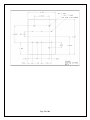
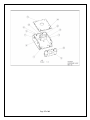
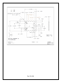
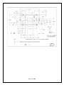
Appendix D – Drawings
30
Page 3 of 60
Camera Control System
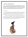
Abstract – This paper describes the design and technical specifications for a Camera
Control System that helps a handicapped wheelchair user with limited use of his or her
hands point a camera. Battery powered motors and a joystick control the pointing of a
camera in two axes. Large, three-axis motorized camera control systems are available, but
this system is a relatively small unit that is designed to be mounted on a wheelchair.
INTRODUCTION
This project came about as a result of meeting between Shari Rose, a resident at the
Cerebral Palsy Research Foundation in Sedgwick County, Kansas and the authors, who are
engineering students at Wichita State University. Shari, who uses a wheelchair, stated that she
had trouble using her single lens reflex camera, because she has limited use of her hands.
The Camera Control System provides motorized, mechanical movement of an attached
camera about two axes; rotation about the vertical axis (pan), and rotation about the transverse
axis (tilt). The motions are controlled by a joystick. The joystick provides user input that is
converted into motor commands via an Arduino digital controller. Limited (90 degrees) rotation
about the longitudinal axis (axis of the lens) is available by manual means.
Page 4 of 60
Constraints
Our client wanted a fairly large range of pitch movement (we set it to 45 degrees down
and 70 degrees up), and a complete 360 degree pan. She also requested provisions for quick
disconnect of the camera, and the ability to move it from landscape to portrait orientation. The
system should be compact and self-contained, and mount easily to her wheelchair. It should be
capable of working with a camera and lens that weigh 720 grams.
Standards
As a potential commercial product, we tried to stick to commercial-off-the-shelf (COTS)
components. As a self-contained product, no industry communications standards were needed.
To be successfully commercialized, the product would have to meet Underwriter Labs (UL)
safety standards.
The camera mounting screw is a standard ¼-20 machine screw that is used by all cameras
sold in the USA.
The battery charger is a standard 11.1 volt lithium-polymer balanced battery charger.
The continuous motion servo size is Standard size.
Page 5 of 60
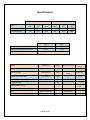
Specifications
Case
No load
Full load (1.8 lb)
Current
(mA)
70
Min
Voltage
(V)
11.5
Power
(mW)
805
70
11.5
805
Current
(mA)
180
Max
Voltage
(V)
11.5
Power
(mW)
2070
240
11.5
2760
Min
Max
Battery No Load Discharge Time
21 Hrs
8 Hrs
Battery Full Load Discharge Time
21 Hrs
6 Hrs
Battery Charge Time
Items
2.5 Hrs
Dimensions
Weight
Type / Material
Zippy Lipo Battery (11.1 V, 1500mAH)
100x34x18mm
138g
Servo (HS-311)
53x20x41mm
43 g
Motor (Servocity 1RPM)
37x37x76mm
142g
3 cell, 25C
Continuous
servo
Torque: 2995 ozin
75x54mm
28g
5g
Arduino Uno
Joystick (2-axis)
4.8 V -6V
3V-12V
6V-20V
Max load:
9lb
Quick release mount
PCB Board
Box
Aluminum Parts
Operating
range
80x60mm
Refer to drawings
Refer to drawings
Page 6 of 60
Acrylic Plastic
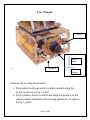
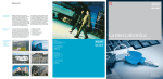
User Manual:
ON
1. ON/OFF
OF
F
2. Joystick Control
Platform
Angle
Fig. 1
3. Charger In
Base
Rotation
Instructions on using the product:
1. The product can be powered on when needed using the
switch as shown in Fig.1, part 1.
2. The joystick is used to control and align the position of the
camera which mounted on the moving platforms. As shown
in Fig.1, part 2.
Page 7 of 60
a. The two-axis joystick is used to rotate the platform
clock-wise or anti-clockwise by moving the joystick
right or left
b. The angle alignment can be controlled for up or
down movement by moving the joystick up or
down.
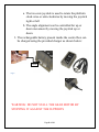
3. The rechargeable battery present inside the control box can
be charged using the provided charger as shown below:
4 Pins
Fig. 2
WARNING: DO NOT STALL THE GEAR MOTOR BY
STOPPING IT AGAINST THE SUPPORTS
Page 8 of 60
Theory of Operation
The product is powered from an 11.1 V rechargeable lithium polymer battery which is
connected to the power switch. When the switch is on, Arduino Uno board gets the input voltage
of 11.1 V. Arduino board regulates the 5V supply and 11.1V supply to the circuit board. When
the joystick is moved left or right, the analog value of the potentiometer is read by the arduino
board and sends the signal to the servo motor for clockwise or counter-clockwise rotation. Servo
motor is also powered by the 5V supply from the circuit board. When the joystick is moved up or
down, the analog value of the potentiometer is read by the arduino board and the signal is sent to
the two inputs of L272 amplifier in the circuit board. The amplifier is powered with the 11.1 V
supply from the board. The input supply to the motor is provided from the amplifier’s output
which triggers the motor to change its polarity and rotate in a desired direction.
Scenario of use:
People with disabilities with trouble in holding the camera and taking the pictures can use
the product. The product can be easily mounted to the wheelchair or a tripod.
Walkthrough of typical operation:
The product is used to align and rotate the position of the camera so that the camera is
stable and the weight of the camera is supported by the product. The user can manually take the
snapshot.
Unique features of the product:
The product is designed to handle the weight of professional camera and lens up to 2.2
pounds. The product is cheaper in comparison to the products available in the market and it can
be easily built using the parts available in the market. The camera can be positioned to take the
pictures of the sky and ground and also take the pictures all around. The product is specifically
built based on the need of specific client Shari Rose.
Benefits for the user:
People with disability will get a platform for using their camera to take nice quality
pictures with the ability to control and align the camera.
Alternative solution:
One of the alternatives is to have someone help the person with disability to carry the
camera or wait for longer time to allow the person to take the picture. Other alternative is to buy
the similar products which are very expensive and is built for the professional filmmaker for
video shooting purposes.
This product provides solution to the specific people with disabilities and the product can
be mounted on wheelchair which aids the client to be independent and enjoy their passion of
photography as a hobby or could be even used as the professional career.
Page 9 of 60
Technical Description
Our product consists of a wheelchair mount, an enclosed box, a rotating platform, a
tilting platform, and an adjustable camera mount.
The wheelchair mount uses a commercial wheelchair mounting clamp to hold the camera
control system in a convenient position for the user. It is made from two steel tubes welded
together a right angle, and a plastic platform. The platform is secured to the mounting tube
assembly with conduit clamps, to allow angular adjustment of the base. The wheelchair mount is
attached to the enclosed box with four screws.
The enclosed box is a clear acrylic plastic box that holds an electronics package, a
continuous motion servo, a gear set, an on-off switch, and a joystick.
The electronics package consists of a battery, Arduino controller, and a circuit board. The
battery is a commercially available 12 volt, 1500 milliamp rechargeable, lithium-polymer unit. It
consists of three cells connected in series. The Arduino controller takes 4-bit commands from the
joystick controller, and converts them into power commands for the servo and motor. These
components are more fully described in the theory of operation.
The continuous motion servo is a commercially available (Hitech HS-311) unit that has
been modified to run continuously. It has 48 inch-ounces of torque at 4.8 volts and runs at ~52
rpm at 4.8 volts.
The gear set consists of two laser-cut plastic gears approximately .25 thick. The smaller
gear is attached to the servomotor shaft, and has 10 teeth. The larger gear is attached to the
rotating platform, and has 40 teeth. Thus the gear set provides a speed reduction of 4:1 to the
servomotor.
The joystick is a commercially available, 2-axis controller.
The rotating platform is fixed to the top of the base with a rotating ball bearing assembly.
It has supports for the tilting platform, a shaft that mates with the first (4:1) gear set, and a motor
that moves the tilting platform through a second gear set.
The rotating ball bearing assembly is a lazy susan turntable with a four inch by four inch
rectangular base, and a 2-3/16 inch diameter hole through its' center.
There are three tilt platform supports that are screwed to the rotating platform base, and
provide room for the tilt platform movement, in addition to mounting spot for the tilt motor. A
hole at the top of each support is used to hold the geared shaft that connects the rotating platform
to the tilt platform.
The tilt electric motor is a 12 volt, one revolution per minute gear motor that provides
2,995 inch-ounces of torque. This high torque is needed to hold the tilt platform, camera mount,
and camera in place when the motor is de-energized.
Page 10 of 60
The motor gear is a 32 tooth brass gear with a 1.00 inch pitch diameter. It is secured to
the six millimeter motor shaft with a set screw.
The tilting platform holds the camera mounting system, and connects to the tilting
platform with a geared shaft that meshes with the motor gear.
The tilt platform is attached to the rotating platform with three blocks that are drilled to
hold the geared shaft securely with set screws to the geared shaft. The tilt platform rotates about
the axis formed by the geared shaft. The gear on the tilt shaft is identical to the gear on the
motor, so the gear ratio is 1:1.
The camera mounting system is a commercial product that we slightly modified. We
replaced a small lever that locks the camera mount ball with a larger one that is easier for a
handicapped person to move. This system provides a quick release for the camera by means of a
separate base that attaches to the camera through the mounting screw hole. It also gives a means
of switching the camera from landscape to portrait orientation.
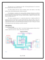
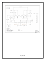
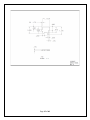
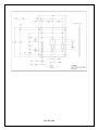
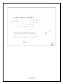
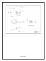
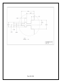
Schematics:
Circuit Board Design:
Circuit board designed using “Eagle” circuit board designing program as shown in Fig.3
with the connection to the servo, motor, power supply and joystick
Fig. 3
Page 11 of 60
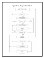
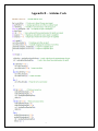
Arduino Board Program:
Arduino code was written using the arduino compiler “Sketch” and uploaded to the
Arduino via USB cable.
A program flowchart is in Appendix A
A code listing is in Appendix B
Structural and Mechanical Design:
An indented parts list is in Appendix C at the end of the report.
Drawings of the mechanical parts are in Appendix D
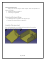
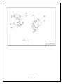
Assembly of the camera stand:
Step 1: walls containing the servo assembled on the bottom platform of the control box.
Step 2: three sides of the control box assembled.
1
2
Page 12 of 60
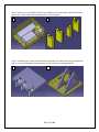
Step 3: battery, servo and main electrical set (arduino & circuit board) are placed in the box.
Step 4: the 4 pieces that make rotating shaft are glued together.
3
4
4
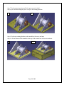
Step 5: aluminum pieces that will contain the pitch shaft are connected to the pitch paltform
Stpe 6: screw two triangular aluminum pieces to the top of the rotating platform
5
6
Page 13 of 60
Step 7: fix the motor in postion and fix the gear to motor’s shaft
Step 8: place the third triangular piece on top of the rotating platform
7
8
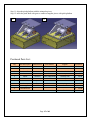
Step 9: fix the top rotating platform to the turntable with screws and nuts
Step 10: fix the bottom of the turntable to the top of the control box with screws and nuts
9
10
Page 14 of 60
Step 11: align the pitch platform with the triangular pieces
Step 12: insert the pitch shaft with gear to connect triangular pieces with pitch platform
11
12
Purchased Parts List:
Qty
1
2
1
1
1
2
1
1
1
1
Part Description
Arduino
Acrylic Plastic
Aluminum Sheet
Servo
Motor
Gear
Turntable
Battery
Charger
Miscellaneous
Manufacture
Arduino
Part Number
Uno
Servocity
Servocity
Servocity
Shepherd
Zippy
Newer
HS-311
RZ12-3000-1RPM
615270
9547
Z15003S20C
40061517
Supplier
WSU
Aluminum Yard Store
Aluminum Yard Store
servocity.com
servocity.com
servocity.com
ACE Hardwar Store
Hobbyking.com
Amazon.com
Total
Page 15 of 60
Price/Unit
$
$ 11.50
$ 26.50
$
7.99
$ 24.99
$ 12.99
$
4.99
$
9.39
$ 12.10
$ 15.00
$ 149.94
Usability Study
Usability Study –
Date –
Participants -
Training Evaluation -
Meeting 1
Nov 14, 2013
Saeed Alsaleeb
Bill Drescher
Kusay Kharmandh
Rupak Poudel
Shari Rose
Participants were the design team and the project client.
Product demonstration and verbal instruction.
Observation and verbal responses.
Results – At this meeting, our main purpose was to test the mounting of the Camera Control
System to the wheelchair and get Shari’s comments. The mount we brought to the meeting was
obviously way too long (high), so we discussed alternate designs. We mounted Shari’s SLR
camera on the device (on a table), to demo it, and discovered that the motor stop torque was
insufficient to hold the camera tilt platform in place. (The motor had enough torque to move the
camera, but after a certain angle was exceeded, the tilt platform continued to move when the
motor was unpowered.) Shari observed that the joystick control lever was very short, and that a
longer one might be easier to use.
Actions Taken – A new higher torque motor was ordered and installed. The new motor has 2,995
in.-oz. of torque compared to the old motor’s 613 in.-oz. of torque. It is also slower; 1 RPM vs.
6 RPM. Two possible new mounts were designed and drawn, and transmitted to Greg Carpenter
at the CPRF machine shop for his evaluation and construction. Greg decided to build the mount
that consisted of two tubes ~.75 inch in diameter, welded together at a right angle. A new longer
(3”) joystick lever was designed and 3D printed on the Thing-O-Matic.
Usability Study –
Date –
Participants -
Training Evaluation -
Meeting 2
Nov 19, 2013
Saeed Alsaleeb
Bill Drescher
Kusay Kharmandh
Rupak Poudel
Shari Rose
Participants were the design team and the project client.
Product demonstration and verbal instruction.
Observation and verbal responses.
Results – Again at this meeting, our main purpose was to test the new mounting of the Camera
Control System to the wheelchair and get Shari’s comments. Trying the new mount, two
problems were apparent. One problem was that putting the down-tube of the mount into an open,
vertical tube of Shari’s wheel chair resulted in the device rotating under the influence of gravity.
The second problem was that the mount still positioned the camera too high for comfortable use.
Page 16 of 60
The new motor now held the camera tilt platform in position when the motor was unpowered.
Shari was OK with the slower tilt motion of the camera, and stated that she might prefer the
slower speed, as it would allow more accurate pointing of the camera. Shari observed that the
camera mount locking lever that to be thrown to allow the camera to be switched from landscape
to portrait orientation was small, and difficult for her to operate. She didn’t like the idea we
proposed to mount the joystick controller separately, and connect it to the main box via wires.
Shari asked if we could mount the joystick onto the main box. After some discussion it was
decided to mount the controller on the back of the box, and that the old, smaller lever would be
preferable in this position. The quick disconnect feature of the camera mount was tested, and
Shari considered it to be acceptable.
Actions Taken – Tom McGuire had provided us with a wheelchair tube mounting clamp earlier
in the semester to try, but we thought we knew better. This was located, dusted off, and found to
fit the Camera Control System mounting tube. A new, longer camera mount locking lever was
designed and 3D printed on the Thing-O-Matic. New holes were cut in the back of the box and
the old, smaller joystick control lever was attached. (It didn’t come up in the usability testing
with the client, but at this time we realized that the electrical power circuit didn’t have an on-off
switch. A small toggle switch was added to the power circuit and mounted to the back of the box.
Labels reading “ON” and “OFF” were printed and added to the box.)
Usability Study –
Date –
Participants -
Training Evaluation -
Meeting 3
Nov 21, 2013
Saeed Alsaleeb
Bill Drescher
Kusay Kharmandh
Rupak Poudel
Shari Rose
Participants were the design team and the project client.
Product demonstration and verbal instruction.
Observation and verbal responses.
Results – The wheelchair tube mounting clamp fit and allowed us to mount the device lower on
the tube. The resulting height was judged to be ‘perfect’, and the device is securely positioned
and no longer moves under the influence of gravity. The side of the clamp that holds the device
is lever actuated, and Shari can use it to remove the camera control system herself. The clamp
can be positioned so that Shari can still use the loop of the tube it is clamped to. Unfortunately,
the side of the clamp attached to the wheelchair is secured with bolts, and takes tools to remove.
The new camera mount locking lever was considered to be acceptable, but a longer length would
be better. However, a longer lever would hit the camera body when the camera is moved to the
portrait position. Shari was very pleased with the positions of the joystick control lever and onoff power switch.
Page 17 of 60
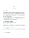
Final Product Survey
Date: Monday, December 09, 2013
1. Is it easy to move the joystick?
It is very easy.
2. Is the input given to the joystick and the movement of the camera as predicted?
Yes, it is as predicted.
3. How much will you be willing to pay for the product like this?
$150 - $200
4. Are you able to mount the camera control system easily on the wheelchair?
No, require help and tools.
5. Are you able to mount and release the camera easily from the system?
Yes, I am
6. Overall, was the product effective in assisting you to take pictures?
Yes, love the product and looking forward to use it.
Page 18 of 60
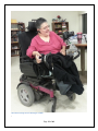
Shari Rose testing the final Prototype at CPRF
\
Page 19 of 60
Historical Perspective
The idea for our project came from a meeting at the Cerebral Palsy Research Foundation
(CPRF), where one of the residents expressed a desire for a way to control the pointing of her
single lens reflex (SLR) camera. A web search revealed that there are commercially available
motorized camera mounts, but they seem to be aimed at professional or serious amateur film
makers. The available camera mounts are large and have 360 degree motion on three axes. They
do not appear to be suitable for someone confined to a wheelchair to use.
We decided to try to make a much smaller and lighter device. We felt that motorized
control of two axes would be sufficient for still photography, and that complete 360 degree pitch
motion was unnecessary.
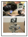
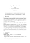
Our first prototype was constructed mostly from wood, and motion was provided by two
servos using pushrods. It was too big for mounting on a wheelchair, and did not provide the
accuracy we wanted but seemed to be a step in the right direction. The motion provided by a
servo (approximately +/- 15 degrees) was too small for the pan axis. See Fig. 4.
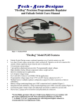
Then we worked on improving our second prototype depending on the feedback we
received from our client and many people we had met during the open house. We improved the
first prototype by exchanging the wood plates for a plastic box. The rotation motion was changed
from a pushrod to a gear set driven by a continuous motion servo. This project was powered
directly from an external power supply using a USB cable. Tilt motion was still provided by a
pushrod. See fig 5.
Feedback from our client indicated that a larger range of pitch motion was needed. For
the third prototype, we replaced the up and down movement servo to a motor providing 2,995
in.-oz. of torque at 1 RPM. This high torque is needed to hold the camera in place against the
camera’s weight. We powered the project with a rechargeable battery.
Page 20 of 60
Fig. 4 Prototype I under construction
Fig 5 Prototype II
Page 21 of 60
Business Viability
The project created by the Senior Design Project was a camera control system for a
wheelchair, which was designed for our client, Shari Rose. The wheelchair holds a rotating
platform that tilts and adjusts in size; this is the base where the camera is placed. The project was
purposely designed to help any person with cerebral palsy or other diseases that limit the person
to a wheelchair and limits their hand mobility, to use a camera.
Our client usually uses a Single Lens Reflex camera but due to limited use of her hands
that she suffered from like most patients with her disability, she had a lot of difficulties whenever
she attempted to use her camera. The task was to find a method of holding a camera for the client
and for patients in general who suffer from the same disability, the goal was to make her be
capable of aiming her camera, and snap photos, with limited use of the hands.
The client wanted a fairly large range of pitch movement, as it made photography more
accessible from the chair. The angles of the mount were set to 45 degrees down and 70 degrees
up. A complete pan of 360 was possible from the mount. Ms. Rose also requested provisions for
quick detachment of the camera. In addition, the ability to move it from landscape to portrait
orientation, amongst other modes of photography, is something that she requested and that the
team thought made perfect sense. The device is compact and self-contained; it’s vital that it
mounts easily and firmly to the wheelchair. And the weight of the camera and lens should be
contained when it weights 720 grams.
The capability of selling such device depends on two aspects:
1. The number of camera users that were confined to a wheelchair after their interest in
photography was a part of their life or a career that they chose to themselves.
2. People whom were already confined to their wheelchairs when their interest in
photography was stimulated, but they felt that their wheelchair was a detriment to their
abilities to participate in the hobby or the business of photography.
With the right amount of marketing, the target audience can and will feel that the product is not
an attempt to make profit off of their disability but really it’s a product that will give them their
ability to become photographers again, or create a new option for those who’ve always been
confined to the chair but developed the interest later in life.
Considering the market which will exist for both the general criteria stated above, and the
interest in professional photography is on the rise, then it seems like a viable option to actually
develop the product. The product, despite being a privilege rather than a right, could be covered
by insurance and disability services.
Another market that could fit the product is that of mental health services and care. In a
higher percentage than in normal cases, wheelchairs users experience a few mental disorders;
depression and anxiety being two of the most major. Photography could be the medicine to these
issues.
Page 22 of 60
Future Work
Future development – Before we deliver our project to our client, we intend to add two
limit switches to the tilt platform to prevent it from contacting the supports and stalling the tiltmotion motor. The motor with its’ integral plastic gear train, is quite powerful (2,995 in-oz. or
over 15.5 lb-ft of torque). If it is stalled, it is capable of shredding the final gears in the gear train.
In fact, we believe this is what happened just before our display at Exploration Place. Some
safety improvements would need to be made before the project could be released commercially.
Specifically, the tilt platform gears should be covered and the pinch injury potential between the
tilt platform and its’ supports needs to be evaluated.
Redesign – The camera mount is a commercially available piece that provides manual,
three-axis motion and quick disconnect for the camera. The quick disconnect is needed by our
client, and the ability to rotate the camera from a landscape orientation to a portrait orientation
was also requested. The part we purchased has the capability needed, but the three-axis freedom
is over-kill. The camera mount also moves the camera up several inches, affecting the mounting
system. This raising of the camera also affected the stop-position holding of the tilt platform,
requiring us to go with the highest torque (and thus slowest) motor we could buy. A much
simpler and lower profile camera mount, with quick disconnect and only one-axis motion would
be very useful.
The project we produced is obviously a prototype, made with the tools and materials that
were available to us in the senior-design lab. We’re not manufacturing engineers, but it seems
plausible that design for manufacturing could reduce the part count and simplify the assembly of
the device. Injection molding might offer great manufacturing cost savings in large scale
production.
The control program we are using is quite simple, and the full Arduino processor may be
over-kill. A custom integrated circuit could provide adequate functionality and savings in size
and power requirements.
Added functionality – Based on the comments of our client, it seems that we hit the spot
of meeting her requirements and desires.
Unneeded complexity – The rotating platform of the device is capable of continuous 360
degree rotation. This could lead to problems with excessive twisting of the motor power wires. It
may be possible to control this through programming.
Page 23 of 60
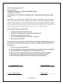
EECS Senior Design Fall 2013
Project Contract
CAMERA CONTROL SYSTEM FOR WHEELCHAIR
Team Name: Team 6 (3!)
Team Members: Saeed Alsaleeb, William Drescher, Ahmad Kusay Kharmandh, Rupak
Poudel
The product we are working on is to build a control system for the wheelchair clients to assist
them in using their camera. People with disabilities often have difficulty in holding the camera
steady. We are working for a client at CPRF, Shari Rose. We are making the product to mount
on her wheelchair which can be easily controlled with joystick. The name of her camera that we
will be working on is E-620 Olympus. One of the lenses is 14-42 mm ZUKO lens.
Functions and Features of the product:
360 degree pan rotation on vertical axis
-45 degree to +60 degree pitch rotation on horizontal axis
Quick release mount for the camera
Easy to mount the product on our client’s wheelchair
Battery powered product
Our product will be tested by our client Shari Rose. We will go to CPRF and have her try
the product and get the feedback from her. We will be asking the following questions for
her feedback:
7. Was it easy to move the joystick?
8. Was the input given to the joystick and the movement of the camera as predicted?
9. How much will you be willing to pay for the product like this?
10. Were you able to mount the camera control system easily on the wheelchair?
11. Were you able to mount and release the camera easily from the system?
12. Overall, was the product effective in assisting you to take pictures?
_____ Saeed Alsaleeb ________
______William Drescher________
____Kusay Kharmandh____
______Rupak Poudel____________
Page 24 of 60
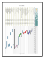
Schedule
Page 25 of 60
Appendix A - Program Flow Chart
Page 26 of 60
Appendix B – Arduino Code
Page 27 of 60
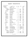
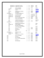
Appendix C – Indented Parts List
INDENTED PARTS LIST
PART NUMBER
0100000-101
0101000-101
0101001-101
0101001-201
0101001-203
0101002-101
0101003-101
N/A
N/A
0102000-101
0102001-101
0102002-101
0102003-101
0102004-101
0102005-101
0102006-101
0102007-101
0102008-101
N/A
N/A
0102009-101
HS-311
0102010-101
0103000-101
N/A
N/A
N/A
N/A
0103001-101
0103002-101
0103003-101
0103004-101
N/A
0103008-101
0103005-101
0103005-103
0103005-105
0103006-101
NOMENCLATURE
QTY FIND #
ASSEMBLY
1
1
MOUNTING ASSEMBLY
1
2
MOUNTING TUBE WELDMENT
1
3
VERTICAL TUBE
1
4
HORIZONTAL TUBE
1
5
CONDUIT CLAMP
3
6
MOUNTING PLATFORM
1
7
6-32 X .375 SCREW
6
8
NO. 6 WASHER
18
9
ENCLOSURE ASSY
1
10
BOTTOM PANEL
1
11
BACK PANEL
1
12
FRONT PANEL
1
13
LEFT PANEL
1
14
RIGHT PANEL
1
15
TOP PANEL
1
16
SERVO PANEL
1
17
SERVO PANEL
1
18
4-40 X .75 FLATHEAD SCREW
16
19
4-40 NUT
16
20
SERVO SHIM
A/R
21
SERVO MOTOR
1
22
GEAR, 10 TOOTH
1
23
ROTATING PLATFORM ASSY
1
24
BEARING
1
25
6-32 X .375 FLATHEAD SCREW
4
26
6-32 NUT
4
27
NO. 6 WASHER
4
28
ROTATING PLATFORM
1
29
TILT PLATFORM SUPPORT
1
30
TILT PLATFORM SUPPORT
1
31
TILT PLATFORM SUPPORT
1
32
4-40 X .312 FLATHEAD SCREW
9
33
GEAR SHAFT ASSY
1
60
RECTANGULAR SHAFT
2
34
RECTANGULAR SHAFT
1
35
RECTANGULAR SHAFT
1
36
GEAR, 40 TOOTH
1
37
Page 28 of 60
MAT'L
STEEL
STEEL
STEEL
ALUMINUM
ALUMINUM
ALUMINUM
ALUMINUM
STEEL
SOURCE
MFG
MFG
MFG
COML
COML
COML
MFG
COML
COML
MFG
MFG
MFG
MFG
MFG
MFG
MFG
MFG
MFG
COML
COML
MFG
Hi-Tech
MFG
MFG
COML
COML
COML
COML
MFG
MFG
MFG
MFG
COML
ACRYLIC
ACRYLIC
ACRYLIC
MFG
MFG
MFG
MFG
STEEL
STEEL
STEEL
ACRYLIC
STEEL
STEEL
ACRYLIC
ACRYLIC
ACRYLIC
ACRYLIC
ACRYLIC
ACRYLIC
ACRYLIC
ACRYLIC
STEEL
STEEL
ACRYLIC
ACRYLIC
0103007-101
0103007-103
N/A
638150
N/A
615270
N/A
0106000-101
0106001-101
0106002-101
0106003-101
N/A
N/A
N/A
N/A
0104000-101
N/A
0104001-101
N/A
N/A
N/A
N/A
N/A
N/A
0105000-101
0105001-101
615270
N/A
N/A
N/A
N/A
N/A
N/A
UPPER SHAFT COLLAR
LOWER SHAFT COLLAR
4-40 X .25 SCREW
ELECTRIC MOTOR
SCREW
PINION GEAR, 32 TOOTH
SET SCREW
TILTING PLATFORM ASSY
TILTING PLATFORM
ROTATION BLOCK
RELEASE LEVER
6-32 X .75 FLATHEAD SCREW
4-40 X .25 SET SCREW
CAMERA MOUNT ASSY
3/8-16 X .5 FLATHEAD BOLT
ELECTRONICS PACKAGE
ARDUINO DIG CONTROLLER
CIRCUIT BOARD
BATTERY, RECHARGABLE
JOYSTICK/W CIRCUITBOARD
6-32 X .375 SCREW
6-32 NUT
SPST SWITCH
WIRE
GEAR SHAFT ASSY
SHAFT
PINION GEAR, 32 TOOTH
6-32 X .375 SCREW
6-32 NUT
NO. 6 WASHER
6-32 X .375 FLATHEAD SCREW
6-32 NUT
NO. 6 WASHER
Page 29 of 60
1
1
2
1
4
1
1
1
1
3
1
6
3
1
1
1
1
1
1
1
2
2
1
A/R
1
1
1
4
4
4
4
4
4
38
39
40
48
49
50
51
41
42
43
47
44
45
46
47
52
53
54
55
61
62
63
64
65
56
57
58
66
67
68
69
70
71
ACRYLIC
ACRYLIC
STEEL
MFG
MFG
COML
servocity
STEEL
COML
BRASS
servocity
STEEL
COML
MFG
ALUMINUM MFG
ALUMINUM MFG
PLASTIC
MFG
STEEL
COML
STEEL
COML
DMKFoto
STEEL
COML
COML
MFG
STEEL
STEEL
STEEL
BRASS
STEEL
STEEL
STEEL
STEEL
STEEL
STEEL
COML
COML
COML
COML
COML
MFG
MFG
servocity
COML
COML
COML
COML
COML
COML
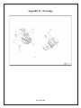
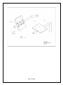
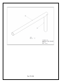
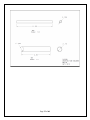
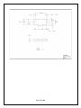
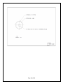
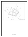
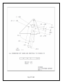
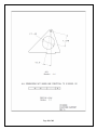
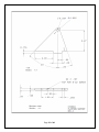
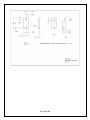
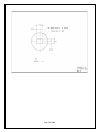
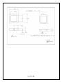
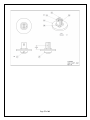
Appendix D – Drawings
Page 30 of 60
Page 31 of 60
Page 32 of 60
Page 33 of 60
Page 34 of 60
Page 35 of 60
Page 36 of 60
Page 37 of 60
Page 38 of 60
Page 39 of 60
Page 40 of 60
Page 41 of 60
Page 42 of 60
Page 43 of 60
Page 44 of 60
Page 45 of 60
Page 46 of 60
Page 47 of 60
Page 48 of 60
Page 49 of 60
Page 50 of 60
Page 51 of 60
Page 52 of 60
Page 53 of 60
Page 54 of 60
Page 55 of 60
Page 56 of 60
Page 57 of 60
Page 58 of 60
Page 59 of 60
Page 60 of 60