1
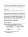
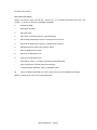
31
GDS Helpsheet
World Leaders in Computer Controlled Testing
Systems for Geotechnical Engineers and Geologists
Hardware
Advanced Controller
Installing Remote Feedback Module Upgrade
1. Introduction
The Remote Feedback Module (RFM) upgrade consists of six components:
1.
2.
3.
4.
5.
6.
The RFM02 personality module which is customised to the transducer
The RFM01 PCB daughter board which goes inside the controller
Cable harness
Installation kit
Upgraded firmware for your GDS pressure controller
A transducer (optional)
2. The RFM02 Personality Module
The RFM02 Personality Module is contained in a small cast aluminium box painted beaver brown.
The box is approximately 120mm x 70mm x 60mm. There is a five pin Lemo socket in one end
(labelled FROM TRANSDUCER). Your Transducer has a flying lead with a cable plug which plugs
into this connector. At the other end of the RFM02 Personality Module is a flying lead with a 10
pin Lemo cable plug. This is the output from the personality module and it plugs into your
controller (after it has been converted). The RFM02 Personality Module provides 10v excitation to
your transducer and amplifies the output signal of the transducer to give an output of +/-10v.
3. The RFM01 PCB Daughter Board
Before attempting to install the RFM01 PCB you should change the firmware in the main GDS
controller PCB. This procedure is described in GDS Helpsheet # 9. The existing firmware
(probably labelled 3.5 or 3.4.1) should be removed and the new firmware labelled 5.0 or higher
should be inserted.
The RFM01 PCB is installed inside your controller as described below. The PCB generates the
10v excitation for your transducer and converts the +/-10v output of the RFM02 personality
module into digital format. To install the RFM01 PCB first remove the main GDS PCB from the
GDS digital controller. This procedure is described in GDS Helpsheet # 7.
The RFM01 PCB is shipped connected to its supporting brackets. It cannot be installed with
these supporting brackets in place. It is first necessary to remove them by unscrewing the four
cross-headed screws holding the two support brackets on to the RFM02 PCB.
You are now ready to connect the RFM01 PCB to the main GDS controller PCB. First become
familiar with the alignment. The ten pin connector (CON1) on the component side of the RFM01
GDS Helpsheet 31 - Page 1
PCB should be vertically overhead LK4 and LK5 on the main GDS controller PCB. There are also
two rectangular cut-outs on the corners of the RFM01 PCB these are designed to clear the
heatsink and CON3 on the main GDS controller PCB.
There are four sets of connectors on the solder side (underside) of the RFM01 PCB. These must
all be mated with matching sockets on the main GDS controller PCB. The first one to be
connected is the 12 pin (in a single line) connector which is on a flying lead containing three wires.
This connector plugs into the bottom half of the IC81 chip carrier. If you have the main GDS
controller PCB orientated so that CON 4 is at the top and CON 6 to your right then push the 12 pin
connector on the flying lead into the bottom half of the IC81 chip carrier so that the yellow flying
lead is to the right and the black flying lead is to the left. Check that you have inserted this
connector so that no legs are overhanging the edges (it should fit perfectly) and then push the
connector securely home.
The remaining three connectors are all double row connectors, one with 14 pins, one with 24 pins,
and one with 28 pins. The 14 pin connector mates with the chip carrier for IC84 on the main GDS
controller PCB. The 24 pin connector mates with the chip carrier for IC91. The 28 pin connector
mates with the chip carrier for IC82.
Position the RFM01 PCB on the main GDS controller PCB so that the PCBs are orientated
correctly and the three sets of connectors are resting gently on their correct chip carriers. Check
that all of the pins are properly aligned. A light may be helpful at this point to let you look between
the two PCBs (you need to be gentle at this stage because the RFM01 PCB can tilt from side to
side). When you are certain that all alignments are perfect push the RFM01 PCB into the chip
carriers on the main GDS controller PCB. This sometimes takes quite a lot of force (maybe 5 kg)
because there are a lot of pins to locate simultaneously. It is best to hold your thumbs against the
back of the connectors to be pushed together and your forefingers taking the load on the other
side. This enables you to see what you are doing as well. The connectors normally plug in with a
definite movement. When the two boards are firmly pushed together the spacing between the
plastic chip carriers and the plastic on the bottom of the pins must be even (about 1mm gap).
Check that all pins have mated correctly and that none have been bent out or under.
The supporting brackets can now be pushed onto the main GDS controller PCB and slid into
position so that the four cross headed screws and washers removed above can be replaced. The
RFM01 PCB is now securely fixed to the main GDS controller PCB.
4. Cable Harness
The cable harness consists of approximately 0.8m of eight way cable connected to a 10 way
Lemo connector in a circular flange at one end and to a 10 way flat plastic connector at the other
end. The diagram below shows the position for the cable in the GDS controller case.
In order to install the cable you will need to cut a hole in the controller case at the fan end as
shown above. To help you do this the following tools have been supplied:•
•
Q-MAX sheet metal punch (31mm)
8mm Allen Key (used to drive the Q-MAX)
GDS Helpsheet 31 - Page 2
•
•
•
3.3mm drill bit
10.2mm drill bit
Centre punch
First cut the 31mm hole for the cable and connectors to pass through. You will need to use the QMAX sheet metal punch for this. Use the centre punch to mark a position on the controller case
55mm from the back of the controller (as shown in the diagram above) and equidistant from the
top and bottom of the case. Use the 3.3mm drill to drill a pilot hole at this point. Enlarge the hole
using the 10.2mm drill. Use the Q-MAX sheet metal punch to enlarge the hole to 31mm. The
instructions for using the Q-MAX are written on the packet.
Remove the screws and washers from the flange and put it in position. Mark the position of the
three holes in the flange using the centre punch. Drill the three holes using the 3.3mm drill
provided.
Make sure you protect the electronics of the controller against metallic cuttings and remember to
clean the case out carefully when you have finished.
The flange can now be fixed permanently in position using the screws and washers provided.
Position one washer under each screw head and one washer under each nut.
5. Connecting the System Together
When the cable harness has been fixed in position and the RFM01 PCB has been attached to the
GDS PCB you can replace the GDS PCB in the case and re-connect the cables you removed
when the GDS PCB was taken out of the case. Remember helpsheet # 7 tells you where
everything goes. Replacing the short green and yellow cable which is attached to the IEEE
connector can be awkward, the pin on the end of the cable is pushed into the right hand side hole
in LK3 which is just underneath the RFM01 PCB. The 10 way flat plastic connector on the end of
the cable harness should now be pushed onto CON1 of the RFM01 PCB. The cable has been
manufactured so that the connector automatically aligns itself in the right way. The red wire
should mate with +V and the white cable with Vin. The controller top plate can now be replaced.
At this stage do not plug anything into the new RFM connector on the RH end of the controller.
Power the controller on. You will see that the start-up message has changed. The controller
may show the message WARNING _ INITIALIZE. If so then press 0,0,1 and then enter the
correct IEEE address. The WARNING _ INITIALIZE message will then go away when you press
RESET,9 to perform a power-on reset. The WARNING _ INITIALIZE message tells you that all of
the information stored in battery backed RAM has been corrupted and should be reset. This
stored information includes IEEE address, zero offset, and all of the RFM parameters.
You will need to read the handbook updates supplied with the upgrade to understand all the
capabilities of the new firmware.
To summarise the capabilities the key sequence RESET, 0, 4 will give you access to the manual
RFM facilities i.e. the RFM FUNCTION menu. When the RFM FUNCTION prompt is displayed a
menu of functions are available by pressing various keys as shown in the RFM FUNCTION MENU
given over the page.
You should ensure the RFM is inactive by using the key sequence RESET,0,4,1 as described
above. Then set the range, decimal places, and max and min values for corrective action. You
may now power-off, connect the RFM02 personality module into the RFM connector on the
controller and plug the transducer into the RFM02 personality module. When you turn the
controller back on the display will say GDS DC v5.0 + RFM and the second display zone will say
NO RFM. If you then activate the RFM using the key sequence RESET,0,4,0 and then press
RESET the second display zone will show the value read from the RFM transducer.
In order to control the GDS DC from a computer using the RFM you will need to read the
GDS Helpsheet 31 - Page 3
amended user manual.
RFM FUNCTION MENU
Please note that the right arrow Æ key returns you to the RFM FUNCTION menu when the
symbol -> is shown on the end of a displayed message.
0
Activate the RFM
1
De-activate the RFM
2
Set range value
3
Set number of decimal places in controller display
4
Set maximum RFM output value for controller limit correction
5
Set minimum RFM output value for controller limit correction
6
Set RFM soft zero-offset (only if RFM is active)
7
Remove RFM soft zero-offset.
8
Returns to FUNCTION menu.
9
Returns to FUNCTION menu.
+
Puts RFM in control, i.e. Pressure target becomes RFM target.
-
Puts control back to internal pressure transducer.
¨
Æ
invokes/cancels calibration check for RFM02 module
returns to RFM FUNCTION menu when shown on the end of a displayed message.
RESET Always returns you to the FUNCTION menu.
GDS Helpsheet 31 - Page 4