1
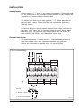
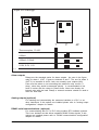
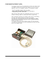
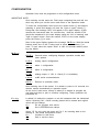
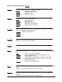
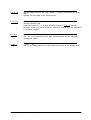
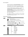
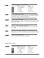
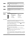
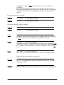
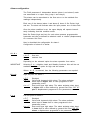
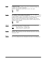
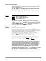
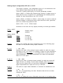
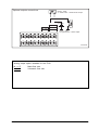
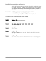
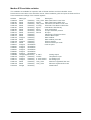
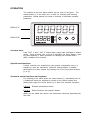
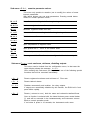
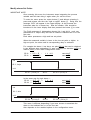
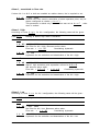
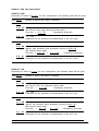
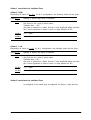
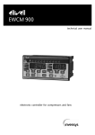
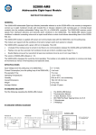
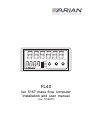
RUN
MAN
OUT1
OUT2
FL40
Iso 5167 mass flow computer
Installation and user manual
rev. 12/2015
PRELIMINARY INFORMATION
This document haves copyright reserved, C Arian.
Referred trademarks are of property of its respective owners.
ARIAN is registered by Arian S.A.
Technical help
If you find problems with the instrument, check its configuration to be
coherent with the application. If still it persists the problem, help can
obtain by the following media:
e-mail
[email protected]
phone/fax 56-2-2418333
web
www.arian.cl
Revision history
rev.
rev.
rev.
rev.
rev.
11/2005
08/2007
07/2009
10/2015
12/2015
First release.
Added functionality for totalized flow count disable
Modified cut-off function on pag 17.
Optional outputs pag 21.
Mass and volumetric flow rate.
GENERAL DESCRIPTION ......................................................................... 4
PART CODE .................................................................................................................... 5
TECHNICAL SPECIFICATIONS ..................................................................................... 6
INSTALLATION ........................................................................................... 7
Analog inputs. ................................................................................................................. 7
External reset inputs. ...................................................................................................... 7
Alarm outputs .................................................................................................................. 8
Analog outputs (optional) ................................................................................................ 8
RS485 serial communications. (optional) ....................................................................... 8
Power supply ................................................................................................................... 9
Panel assembly ............................................................................................................... 9
CONFIGURATION FROM PC (RPS) ........................................................ 10
CONFIGURATION .................................................................................... 11
General Configuration menu ( O P E r ). ....................................................................... 12
Input configuration ........................................................................................................ 14
Upstream temperature input.......................................................................................... 14
Upstream pressure input ............................................................................................... 15
Differential pressure input ............................................................................................. 16
Flow totalizer ................................................................................................................. 16
Alarms configuration. .................................................................................................... 18
Alarm 2 and pulses output. ........................................................................................... 20
Analog output configuration 4-20 mA. or 0-10V ............................................................ 21
Serial RS485 communications configuration. ............................................................... 23
Modbus RTU available variables. ................................................................................. 24
OPERATION ............................................................................................. 25
Special reset functions. ................................................................................................. 25
Access to special functions and registers. .................................................................... 25
Sub-menu r E A d , examine parameter values. .......................................................... 26
Sub-menu F u n c , reset maximum, minimum, disabling outputs. ................................ 26
Modify alarms Set Points. ............................................................................................. 27
GENERAL DESCRIPTION
The FL40 is a multivariable flow computer and Cad software designed
specifically to be used on differential pressure flow measurement devices
under ISO5167 standard such as orifice plates, nozzles and venturi tubes.
Differential pressure measurement on the primary device is corrected with
upstream pressure and temperature of the fluid in order to calculate instantaneous mass flow .
Arian Flow Cad software allows to select the fluid within a list, describe
the primary device and calculate discharge coefficients, expansion factor
and fluid properties under flow conditions.
Results are stored on a file and downloaded to the FL40.
Inputs
Readings Alarms
-
Standard process variables as 4..20mA, 0..10V,etc. for P , dP and T
Pt100 or thermocouples for Temperature input.
Two programmable external inputs (dry contact) as reset functions.
Totalized flow in 6 high bright 14.5mm height red digits. (Upper display)
Flow rate in lower 4 digits.
Continuous memory, stores last reading of the totalized flow.
Registers maximum and minimum readings of flow rate.
4 alarms assigned independently to preset values of the totalized flow or
rate, linked to the 2 output relays,
Latch and standby functions.
Outputs
Two output relays, with two programmable alarms each ( high and low)
Output pulse with frequency proportional to the analog input. For external
totalizing in PLCs.
Galvanically isolated analog outputs for the flow rate meter: active loop
4..20ma ,0...10V, passive loop 4..20ma.
Communications
RS485 Modbus RTU serial communications reports data to a PC or PLC.
Configuration.
From a PC compatible by means of RPS software.
From frontal push buttons.
FL40
RUN
MAN
OUT1
OUT2
T
P
dP
Transmitters
Pt100
Orifice plate
User Manual FL40, rev.12/2015, www.arian.cl
4
PART CODE
Defining a part number must be done selecting the following options.
Last 2 ones (-420A, -420L), -RS85 are optional that must not be included
if no required.
FL40
-AC
-DC
-420A
-420L
-RS485
-AC :power supply 85...260 Vac, 6 W, 45...65 Hz.
-DC :power supply 18....60 Vdc, 6 W
OPTIONAL OUTPUT
-420L :4..20ma passive loop
-420A :4..20ma active, includes also 0..10Vdc
OPTIONAL
-RS485 :modbus RTU serial communications
For example:
FL40-AC
FL40 , AC power supply , without any optional output.
FL40-DC-RS485
FL40 , DC power supply and modbus RTU serial communications.
User Manual FL40, rev.12/2015, www.arian.cl
5
TECHNICAL SPECIFICATIONS
INPUTS
3 inputs for P, dP and T:
Pt 100, thermocouples, 4...20 mA, 0...20 mA, 0...5 V, 1..5 V, 0..10 V, 0..50 mV.
DISPLAY
Flow totalizer: 6 digits Display (14mm), range 0...999999
Flow rate: 4 digits (9mm), range -999... 9999
OUTPUTS:
Relays, 2 outputs for alarms 250VAC/ 3A., normally open or normally close by software.
Optional:
-420L 4... 20 mA, loop powered, Vdrop 4.5V max. opto isolated (5kV).
-420A 4..20ma Active loop, opto isolated (5kV).
-010V 0.. 10Volts, opto isolated (5kV).
-RS485 modbus RTU serial communications, opto isolated (5kV).
POWER SUPPLY:
Current mode switching power supply.
Versions:
85...260 Vac, 6 W, 45...65 Hz.
20...60 VDC, 6 W, (optional)
CONSTRUCTION:
Aluminum and Polycarbonate;
Total Dimension:
Panel cut:
Weight:
Operation temperature:
User Manual FL40, rev.12/2015, www.arian.cl
IP65
DIN 1/8; 96 x 48 x 180 mm.
92 x 45 mm.
350 grams.
0 ... 50 °C.
6
INSTALLATION
Analog inputs.
Analog inputs for T, P and dP are show in the drawing. Terminals #3 and
#12 are connected to the instrument internal ground and can used for the
connection of external shield of sensors cable.
The internal pins that set the input types for T, P, dP are described on
the next page drawing. This is must be done opening the instrument
before panel mounting. Just remove top part half of the cage, without
removing screws.
Cables that bring the sensors signals be apart from cables connected to
the output relays since this are normally inductive loaded. When deactivated this relays can generate high voltage spikes that can cross the
cable insulator and disturb, even damage the input circuit.
External reset inputs.
The instrument haves 2 external inputs for connecting push buttons or
switchs. In the configuration menu is assigned a function to the inputs,
such reset total to cero, reset registered maximum and minimum.
Switchs are connected to terminals #14, #13 and #12 (Gnd)
FL40 connections
ANALOG OUT
Inputs
Reset
RS-485
A
dP P Gnd Ex2 Ex1 B
T
V+ Gnd 90..260Vac
Temperature P. SUP
OUT 1
RELE
Gnd
+V
-I
+I
OUT 2
RELE
Thermocouples
PT100
0..20mA, 4..20mA
0..10V, 0..5V, 0..50mV
FL40_c1
User Manual FL40, rev.12/2015, www.arian.cl
7
Input Pin Settings
P
T
dP
T
P
dP
Thermocouples, Pt-100
0-50mV
4-20mA, 0-20mA
0-10V, 0-5V, 1-5V
FL40_14
Alarm outputs
Relays are the standard option for alarm outputs. As seen in the figure,
relay for alarm 1 (OUT 1) goes to terminals 6 and 7. The one for alarm 2
(OUT 2) to terminals 8 and 9, both are normally open outputs (NO).
Care must be taken on not exceeding the maximum relay current (3
Amp.), since they would be damaged quickly. Is recommended to use
fuses in series with the relays to protect them. Never use directly the
internal relay with the load. Always a external contactor should be used to
drive the final load.
Analog outputs (optional)
For isolating and retransmitting the measured variable to a PLC or another instrument. If this options are installed please refer to "analog output
configuration" chapter for details.
RS485 serial communications. (optional)
For communicating with PC or PLC using modbus RTU software protocol.
This is an isolated out that drives standard RS485 5Volts signals. If this
options are installed please refer to "RS485 communications configuration"
chapter for details.
User Manual FL40, rev.12/2015, www.arian.cl
8
Power supply
The instrument power supply is designed to operate with any voltage
between 90 and 260 volts without need of adjustment. (20VDC to 60VDC
for the DC power supply option). Once start up will continue operating
unless the network fall under 50 VAC. The instrument possesses an
internal 0.5Amp fuse that should be replaced with a similar one.
Panel assembly
Designed for panel assembly in a 92 x 45 mm. cut (Format DIN 1/8)
using clamps included with the instrument.
User Manual FL40, rev.12/2015, www.arian.cl
9
CONFIGURATION FROM PC (RPS)
Two displays versions may be programmed by frontal push bottoms while
one display versions does not have push bottoms, so only can be programmed from a PC compatible computer. The following is needed:
- The PC compatible computer with vga monitor.
- RPS software (download latest version from www.arian.cl)
- Isolating interface cable. Part# RPS-C
While using the RPS system the configurating menus are the same described in following chapter for frontal push bottoms programming.
With de-energized instrument, the interface cable must be connected by
one side to the internal connector as shown in the picture.
The other side of the cable goes to the PC serial RS232 port (DB9).
Once done the connection the instrument must be energized and RPS
software executed in the PC.
The interface cable does optical isolation between PC and instrument.
Concluded the programming you must de-energized the device and then
plug off the interface cable.
User Manual FL40, rev.12/2015, www.arian.cl
10
CONFIGURATION
Operation form must be programed on this configuration menu.
IMPORTANT NOTE:
Once entering on this menu the FL40 stops computing flow and will continue only when you exit the menu and return to the operation mode.
To enter the configuration menu press the center button [•] and without
releasing it, press and release one time the "right or upper" button [^] .
Doing that, the message "KEY" will appear in the upper display. At this
moment the instrument asks for a access key. Now the number 2736
should be introduced in the lower display using the "left or lowering" and
"right or upper" button. Once the number 2736 is in the lower display,
press the button [•] to enter.
Now in the upper display appears the message M E n u. With the lateral
buttons select one of the 5 menus and to press center button [•] to
enter. To quit, select the option "SALi" or wait 16 seconds without pressing any button.
M E n u
O P E r.
General menu, configuring displays, operation modes and
other options.
I n P t.
Analog inputs configuration.
A L - 1
alarm 1 configuration.
A L - 2
alarm 2 configuration.
4 - 20.
analog output, 0...10V, 4...20mA (if it is available)
r 4 8 5
rs485 serial communications.
S A L i
Returns to operation mode.
Once entering one of the menus, if no button is press in 16 seconds, the
devices returns automatically to operation mode.
At the end of each menu, always is asked if is desired to program the
new data and then to quit or continue configuring. These questions are
presented as:
P r o g
is asked if is desired to program or not the instrument with the introduced
values. Selecting "No", values recently placed will be erased and original
values will not change.
N o
Do not program new values.
S i
Set in EEPROM new values.
S A L i
Select “Si”
starting of
N o
S i
for quit (exit) the menu and “N o” for returning back to the
the actual configuration menu.
Continue in this menu.
Quit or exit the menu.
User Manual FL40, rev.12/2015, www.arian.cl
11
General Configuration menu ( O P E r ).
d i s. A
Select the reading for the 6 digit upper display.
M. t o t
Totalized mass flow.
V. t o t
Totalized volumetric flow.
M. r t E
Mass flow rate.
V. r t E
Volumetric flow rate.
d i s. b
Reading for the lower 4 digits display.
o F F
Disabled Display.
M. r t E
Mass flow rate.
V. r t E
Volumetric flow rate.
M A C S
Mass flow rate maximum.
M i n i
Mass flow rate minimum.
P. d i. C
Places a fixed decimal point in the 6 digit higher display. This apply only
when the reading is the totalized flow.
- - - - Without decimal point.
- - -. - -. - -. - - -
P. d i. M
Sets the number of decimal places for the mass rate reading.
Applies for upper and lower displays.
P. d i. V
Same as above, but for the volumetric rate reading.
E t r.1
A function is assigned to the external reset input 1, associated to terminal
#12.
o F F
there is no function assigned.
r S t . N
Reset registered maximum and minimum of rate.
r S t . A
Reset latched alarms.
d i . A L
Disable/restore momentarily the alarm relay outputs.
While disabled the alarms, the "RUN" led on front
panel blinks quickly.
r S t . C
Reset to cero totalized flow.
E t r.2
A function is assigned to the external reset input 2, associated to terminal
#13.
Options are the same described for previous case.
b o t . L
Special function set for the Lowering button [v] on the front panel. (the
left one).
Options are the same described for previous case.
User Manual FL40, rev.12/2015, www.arian.cl
12
b o t . H
Special function set for the "high" button [^] on the front panel (the right
one).
Options are the same of the previous one.
F u . L c
= No,
Si
Special functions lock.
It should be set "Si", to restrict operator access to "F u n c" special
functions menu (e.g.. reset maximum, minimum, alarms, etc.) as described
in operation chapter.
P r o g
= No,
Si
Set "Si" for programming new data. Otherwise data will be lost when
quitting this menu.
S A L i
= No,
Si
Set “Si” for quitting this menu. Otherwise return back to its starting point.
User Manual FL40, rev.12/2015, www.arian.cl
13
Input configuration
Previously must been set the input configurating pins ( for Pt100, Tc,
current or voltage inputs ) as described in the installation chapter.
Characterization of the fluid properties and primary device for the expected operating ranges is done with the Arian Flow Cad software.
As result the software generates a configuration file (extension .sfg )
containing the selected characteristics and operating ranges.
The configuration file is then loaded to the instrument using the RPS
programming software.
Take the *.sfg configuration file that is generated by ArianFlowCad in the
same directory of the project file and place a copy of it in "files"
subdirectory of the RPS software.
Then run RPS software with the FL40 connected to the PC and go to
Menu / Device / FileWrite.
After loading the configuration file to the FL40 go on with the following
input configuration menu in the same RPS software for setting options
related with sensors types you will use.
Upstream temperature input
t . t Y P
Up stream Temperature Input type.
t c
P100
PrcS
thermocouple input
RTD type Pt100 DIN43760 (-136, 450) C.
processes input 4-20mA, 0-10Volts and others.
Depending on selected input type, internal jumpers must be placed as
described on installation chapter.
t c or pt100 P100 , the instrument
Selecting input as thermocouple
will pass to ask for temperature units.
While, if selected process variable input PrcS , the instrument will ask for
the limits or input calibration.
t Y P E
Thermocouple type.
If select thermocouple input, now is set the type and temperature units.
Type
RANGE
t c J
J
(-60, 760) C.
t c k
k
(-100, 1372) C.
t c t
T
(-86, 400) C.
t c r
R
-1 mV, 1767 C.
t c s
S
-1 mV, 1764 C.
t c b
B
-1 mV, 1815 C.
t c n
N
(-139, 1298) C.
t c E
E
(-176, 750) C.
t c PL
Platinel
(0, 1394) C.
t c C
C
(0, 2314) C.
t c d
D
(0, 2314) C.
t c G
G
(0, 2313) C.
User Manual FL40, rev.12/2015, www.arian.cl
14
t Y P E
Processes input type for Temperature input.
Type
Range
0 - 20.
0- 20 milliamperes.
-24 mA, 24 mA.
4 - 20.
4- 20 milliamperes.
2 mA, 24 mA.
0 - 5 v.
0- 5 volts.
-2 V, +12 V
1 - 5 v.
1- 5 volts.
-2 V, +12 V
0 - 10.
0- 10 volts.
-2 V, +12 V
0 - 50
0- 50 millivolts.
-10 mV, +60 mV
L. i n F
= -999... 9999 Celsius degrees
Introduce reading value for input at the lower limit of selected input type.
For example the input is 4-20mA originated in a temperature transducer
that delivers 4 mA at 0 C and 20 mA at 1000 C
In this case is being asked for the reading at 4 mA, that is LinF = 0.
L. S u P
= -999... 9999 Celsius degrees
Introduce reading value for input at the higher limit for selected input type.
For the same previous example, it is asking for reading at 20mA input,
that is LSuP = 1000.
t . d i S
= [ oFF , on ]
Enable or disable temperature measurement.
In case on , the fixed default temperature is used for internal calculations.
t . E r r
= [ oFF , on ]
Enables use of the default temperature for internal calculations when the
temperature sensor fails. In that case no error will be given for flow rate.
t . d E F
= -200,... 2000 Celsius degrees
Default temperature to be used for computations.
Upstream pressure input
P . t Y P
Upstream pressure sensor input type.
Type
0 - 20.
0- 20 milliamperes.
4 - 20.
4- 20 milliamperes.
0 - 5 v.
0- 5 volts.
1 - 5 v.
1- 5 volts.
0 - 10.
0- 10 volts.
0 - 50
0- 50 millivolts.
User Manual FL40, rev.12/2015, www.arian.cl
Range
-24 mA, 24 mA.
2 mA, 24 mA.
-2 V, +12 V
-2 V, +12 V
-2 V, +12 V
-10 mV, +60 mV
15
P . d i S
= [ oFF , on ]
Enable or disable pressure measurement.
In case on , the fixed default pressure is used for internal calculations.
P . E r r
= [ oFF , on ]
Enables use of the default pressure for internal calculations when the
sensor fails. In that case no error will be given for flow rate.
P . d E F
= 0,.. 100 %
Default upstream pressure to be used for computations.
Is entered as percent of the range set for the sensor in the Arian Flow
Cad software.
Differential pressure input
d P . t Y
Differential pressure sensor input type.
Type
0 - 20.
0- 20 milliamperes.
4 - 20.
4- 20 milliamperes.
0 - 5 v.
0- 5 volts.
1 - 5 v.
1- 5 volts.
0 - 10.
0- 10 volts.
0 - 50
0- 50 millivolts.
Range
-24 mA, 24 mA.
2 mA, 24 mA.
-2 V, +12 V
-2 V, +12 V
-2 V, +12 V
-10 mV, +60 mV
Flow totalizer
The FL40 measures and totalize both mass a volumetric flow rates
simultaneusly. The totalized flow is actualized adding each second the
instantaneous flow rate to the last totalized flow.
The reading is presented in the higher 6 digits display and is obtained by
dividing the internal totalized flow value by a constant k.cnt that allows to
adjust for different engineering units.
For example the flow rate is 500kg/hour.
If the input is stable, each second 500 is added to the internal totalized.
If the input is the same for one hour, then 500 had been added 3600
times.
So the totalized had increased 1800000.
If you want to have the totalized reading in kg, you must divide by
k.cnt = 3600.
This way if you reset the instrument and let it work 1 hour with the constant 500kg/hour flow rate, the reading will be 500Kg.
(500kg/hour*3600) / [3600] =500
In order to have the reading in kg with one decimal point ( e.g. 100.3kg),
then you must divide by 360 ( so reading would be 5000 in stead of 500)
and also activate the decimal point as indicated in the general configuration menu.
User Manual FL40, rev.12/2015, www.arian.cl
16
The division constant k.cnt may have any value in the range of
0...999999 .
From the RPS software is entered as a 6 digit number, but from the
instrument frontal push-button is entered in 2 parts, first the 4 less significant digits and then the 2 most significant in order to have a 6 digit
number.
Mass totalizer division constant:
M. kt. 4
= 0... 9999
4 less significant digits
M. kt. 2
= 0... 99
2 most significant digits.
Volumentric totalizer division constant:
V. kt. 4
= 0... 9999
4 less significant digits
V. kt. 2
= 0... 99
2 most significant digits.
t. Inh
= Off, On
Totalized count inhibition enable.
If enabled, each second the flow input is compared with the number set
as F.Lin if lower then the totalized count update is not done.
F. oFF
= Off, On
Flow cut-off enable.
If enabled, the flow is compared with the number set as parameter F.Lin
if lower then the flow is set to cero. This is a lower limit for the input. Use
it for example if you don't want to have input negative values (set F.Lin
=0 ).
F. Lin
= 0... 9999
Flow rate lower limit.
Input lower limit used when enabled some of the 2 preceding options.
Finally from the push buttons you must set
P r o g
= No,
Si
Set "Si" for programming new data. Otherwise data will be lost when
quitting this menu.
S A L i
= No,
Si
Set “Si” for quitting this menu. Otherwise return back to its starting point.
User Manual FL40, rev.12/2015, www.arian.cl
17
Alarms configuration.
The FL40 possesses 2 independent alarms (alarm-1 and alarm-2) each
one associated to a output relay (relay-1 and relay-2)
This alarms can be associated to the flow rate or to the totalized flow
readings independently.
Each one of the alarms (alarm-1 and alarm-2) haves 2 Set Points, high
and low. The alarm will activate when the input passes one of these limit.
Once the alarm condition is set, the upper display will operate intermittently indicating that this condition exists.
Both Set Points (high and low) for each alarm possess programmable
hysteresis and can be defined as absolute value or relative (displacement)
to a common Set Point.
Now is described the configuration for alarm-1.
Configuration of alarm-2 is similar.
ALAr
Selects the variable associated with alarm 1.
r A t E
flow rate
C n t r
totalized flow
Depending on the selected option the alarm operation form varies.
IMPORTANT
Selecting C n t r disables Latch and Standby functions. Also will be not
available the d o n F option for high and low alarms.
When r A t E is selected, then the following parameters are required.
H i g h
High set point for alarm-1.
o F F
o n F h
d o n F
L o u
Disabled.
On/off with hysteresis high alarm. The alarm activates
when input is higher than a value programed in the
parameters menu.
Dual on/off type high alarm. The alarm activates when input
is higher than a value defined by general Set Point "SP. rE"
plus a displacement programed in the parameters menu.
Low set point for alarm-1.
o F F
o n F h
d o n F
Disabled.
On/off with hysteresis high alarm. The alarm activates
when input is lower than a value programed in the
parameters menu.
Dual on/off type high alarm. The alarm activates when input
is lower than a value defined by general Set Point "SP. rE"
minus a displacement programed in the parameters menu.
User Manual FL40, rev.12/2015, www.arian.cl
18
L t c h
Enable Latch alarm.
If enabled, the alarm condition output will be maintained although the
condition that generated it disappears.
Operator must reset the latched alarm from the front panel.
No
disable
Si.
enable
S t b Y
The "standby" function inhibits alarm activation when the operator changes
the Set Point or the instrument is powered up.
If alarm condition is given in that situation, the activation of the alarm-1 is
inhibited until the condition that generates the alarm disappears.
After the condition that generates the alarm disappears (eg. the rate
reading arrived to the new set point) then the alarm is ready to be activated by normal operation.
No
disable
Si.
enable
r E L E
Is specified if the relay-1 will work normally open or normally closed. This
relay is active when alarm-1 condition exists.
d i r
Relay works direct , normally open.
i n v
Works inverted or normally closed.
P r o g
= No,
Si
Set "Si" for programming new data. Otherwise data will be lost when
quitting this menu.
S A L i
= No,
Si
Set “Si” for quitting this menu. Otherwise return back to its starting point.
User Manual FL40, rev.12/2015, www.arian.cl
19
Alarm 2 and pulses output.
Alarm 2 is configured in identical way that is done for alarm 1, but the
output is related to relay 2.
The only difference is an additional option for emitting pulses with the
relay for external counting. Pulses rate are proportional to the analog
input. This way pulses can be count in a PLC.
Once entering Alarm-2 configuration menu the following is requested.
ALAr
Selects operation form of the alarm a relay.
r A t E
alarm set to the flow rate.
C n t r
alarm set to the totalized flow.
P u L S Pulse output on relay-2
Depending on the selected option the alarm operation form varies.
Selecting r A t E or C n t r makes this alarm to operate the same way
as described for alarm-1. If P u L S is selected the output pulses on
relay-2 are enabled and the following is requested.
P.C t E
= 1... 9999
Division constant for output pulses.
Each second it is evaluated how much the totalized flow is increased. A
pulse will be emitted for increase equivalent to the division constant. The
pulses will be emitted by relay-2 in the following second.
For example if the flow rate is 500kg/hour y and the flow totalizer
prescale is k.cnt = 3600, then the totalized will be in kg.
Each unit the totalized flow increases is equivalent to 1kg.
If you need now that the instrument send 1 pulse for each 100kg increase, then set the output prescale P.C t E = 100.
Same way if you need 1 pulse for each kg, set P.C t E = 1.
The maximum number of pulses that can be emitted by second is 100,
but if the output relay is mechanical type (there is the option for SSR
Relay) no more than 4 pulse by second should be allowed because of
speed response limitation of the relay. For this reason the maximum
expected input rates must be considered when you set the constant.
Emitted pulses are always 50% duty cycle. If one pulse/second is emitted
the relay will be 0.5 seconds active and 0.5 second deactivated.
If 4 pulse seconds are emitted relay will be 0.125s active and 0.125s
deactivated.
User Manual FL40, rev.12/2015, www.arian.cl
20
Analog output configuration 4-20 mA. or 0-10V
This output is optional, the configuration menu is in all instruments even
if the optional output board may be not installed.
There are 3 analog output types, all of them galvanically isolated.
Option -420LP, is 4-20ma loop Powered that requires a voltage source in
series with the loop. Its typical use is conditioning and isolating process
variable for other instruments as eg. PLC or DCS.
Option -420AC, is 0-20mA or 4-20mA , active output. Its used to send the
selected variable to instruments whose input should be active (powered)
such as a 4-20ma loop powered valve.
Option -010V, is a 0.. 10Volts output.
Questions in the menu will vary slightly according to board type installed.
Option -420LP
4 - 20
o F F
o n
Option -420AC
t Y P E
o
0
4
0
F F
- 2 0
- 2 0
- 1 0
Disable output.
enabled.
Disabled.
0 to 20 mA.
4 to 20 mA.
0 to 10 Volts.
V A r b
Asks by the variable that will be transmitted. See in the following page
the table for the possible analog output variables.
E. i n F
= -999... 9999
Introduce the value of the selected output variable for which the output
will deliver 4 mA. (or 0 Volts). For example if output for input temperature
was selected, when “E. i n F” = 0, the output will be 4 mA for zero degrees temperature. For lower temperatures the output will descended
down to 3.5 mA. aprox.
E. S u P
= -999... 9999
Introduce the value of selected output variable for which the output will
deliver 20 mA. (or 10volts). For the same example, place “E. S u P” =
1000, then the output will be 20 mA when temperature is 1000. For
higher temperatures the output will rise up to 20.5mA.
CA Li
This refers to output board calibration, is reserved for manufacturer use.
P r o g
= No,
Si
Set “Si” for programming new data. Otherwise data will be lost when
quitting this menu.
S A L i
= No,
Si
Set “Si” for quitting this menu. Otherwise return back to its starting point.
User Manual FL40, rev.12/2015, www.arian.cl
21
Optional outputs connections
+
-
Option -420A
4...20mA and 0...10Volts active output
+
4.5V min.
+
ANALOG OUT
RS-485
B
A
Gnd
+V
-I
+I
PLC
Option -420L
Loop powered 4...20mA output.
420OUTBe
Analog output option variables for the FL40
M. r t E
V. r t E
Mass flow rate.
Volumetric flow rate.
User Manual FL40, rev.12/2015, www.arian.cl
22
Serial RS485 communications configuration.
Serial rs485 communications are optional, although the configuration menu
is in all the instruments, hardware for its operation could not be installed.
The command description for the communications protocol is available as
file in internet (www.arian.cl) and includes tag listing with its properties
and scales.
Characteristics : - RS485 physical protocol with optically isolated interface.
- start bit, 8 data bits, parity bit = 0, stop bit
- communication protocol, Modbus RTU ,functions 03, 06, 10
The questions in the configuration menu are the following.
n o d E
o F F , oN
Enable or disable communications.
b A u d
300, 600, 1200, 2400, 3600, 4800, 9600, 19.2k
Communication speed.
n. S c L
= 1...247
Slave number.
P r o g
= No,
Si
Set “Si” for programming new data. Otherwise data will be lost when
quitting this menu.
S A L i
= No,
Si
Set “Si” for quitting this menu. Otherwise return back to its starting point.
User Manual FL40, rev.12/2015, www.arian.cl
23
Modbus RTU available variables.
This variables are available for inspection with a RS485 interface and the ArianOPC server
Download from www.arian.cl the ArianOPC server, follow instalation guide and open the fl40b.ars file to
have instantaneus readings of this internal registers.
Address
H400000
H400160
H4001b0
H400190
H4001a0
H400168
H400170
H400178
H400198
H4001c8
H400150
H400158
H4001b8
H4001c0
H400010
H400020
H400030
H400040
H400050
H400060
H4000D0
H400100
H400110
H400118
H400120
H400128
H401000
Data type
Real4
ReadOnly
Real4
ReadOnly
Real4
ReadOnly
Real4
ReadOnly
Real4
ReadOnly
Real4
ReadOnly
Real4
ReadOnly
Real4
ReadOnly
Real4
ReadOnly
Real4
ReadOnly
Integer4
ReadOnly
Real4
ReadOnly
Integer4
ReadOnly
Real4
ReadOnly
Integer2
Read/Write
Integer2
Read/Write
Integer2
Read/Write
Integer2
Read/Write
Integer2
Read/Write
Integer2
Read/Write
UnSignIntg2 ReadOnly
Integer4
ReadOnly
Integer4
ReadOnly
Integer4
ReadOnly
Real4
ReadOnly
Real4
ReadOnly
String8
ReadOnly
Units
User_Units
Kg/seg
User_Units
m3/seg
Kg/m3
Kelvin
Pascal
Pascal
Description
Mass Flow Rate in User Units
Mass Flow Rate in MKS units
Volumetric Flow Rate in user units
Volumetric Flow Rate in MKS units
instantaneus fluid density
Input temperature
P1 input absolute presure
dP input
Cdischarge x Expansion factor
Custom table output
Mass totalizer
Mass totalizer pre-scale
Volume totalizer
Volume totalizer pre-scale
main set point
0-100%
Celsius
0-100% sensor
0-100% sensor
User_Units
User_Units
User Manual FL40, rev.12/2015, www.arian.cl
Analog Output
Temperature input
P1 analog input
dP analog input
Maximum registered flow rate
Minimum registered flow rate
identification
24
OPERATION
The location of the front panel buttons can be seen in the figure. The
central button [•] is the main one, is used for selecting and entering
parameters. Lateral buttons are used to increase or decrease selected
parameter.
DISPLAY A
RUN
MAN
OUT1
OUT2
DISPLAY B
Activated alarm
Leds "OUT 1" and " OUT 2" reflect alarm relays state (activated or deactivated) . Once an alarm (AL- or AL-2) is activated, the lower display reading starts blinking (1 time/2 seconds) for advising the operator that a
alarm condition has occurred.
Special reset functions.
If these functions are enabled from the general configuration menu, is
possible to reset the maximums, minimum, latched alarms or disable
momentarily the relay outputs by pressing one of the front panel buttons
[^] or [v].
Access to special functions and registers.
For entering to the menu press the center button [•], immediately one of
2 submenus should be selected by means of the lateral buttons and
finally press again the center button [•] to enter the selected sub-menu.
r E A d
Examine parameters values.
F u n c
Reset functions and outputs disable.
While you are within this menus, the instruments continues measuring the
flow rate.
User Manual FL40, rev.12/2015, www.arian.cl
25
Sub-menu r E A d , examine parameter values.
This menu only permits to examine (not to modify) the values of some
internal parameters.
With lateral buttons you can scan parameters. Pressing central button
returns to normal operation mode.
M. r t E
Mass flow rate reading in defined engineering units
M A CS
Maximum registered mass flow rate .
M i n i
Minimum registered mass flow rate .
V. r t E
Volumetric flow rate reading in defined engineering units.
M. t o t
Totalized mass flow rate.
V. t o t
Totalized volumetric flow rate.
t.
Input temperature in degrees celius.
i n
P. i n
Input presure as 0... 100% of the sensor scale.
dP. i n
Differential presure as 0... 100% of the sensor scale.
S P. r E
Shows general Set Point for alarms configured with relative set points.
Sub-menu F u n c , reset maximum, minimum, disabling outputs.
This menu can be locked from the configuration menu, in that case the
upper display shows the message L o c k .
Once entering this Sub-menu can be selected one of the following special
functions that will be executed immediately.
r S t . N
Resets registered maximum and minimum of Flow rate.
r S t . A
Resets latched alarms.
d i . A L
Disables momentarily and enables the relay outputs.
If outputs are momentarily disabled by this function, the RUN led in front
panel blinks rapidly.
r S t . C
Resets ( returns to cero ) both the mass and volumetric totalized flows.
Once a function is selected with the lateral buttons press central button
[•], and will be executed in the instantaneously and instrument returns
back to normal operation mode.
If no button is press in 16 seconds, the instruments exits menu.
User Manual FL40, rev.12/2015, www.arian.cl
26
Modify alarms Set Points.
IMPORTANT NOTE
Once entering this menu the instrument stops integrating the process
variable and will start doing it again when you exit the menu.
To enter the menu press the center button [•] and without releasing it,
press and release one time the "right or upper" button [^] . Doing that, the
message "KEY" will appear in the upper display. At this moment the
instrument asks for a access key. Now the number 1234 should be
introduced in the lower display and then pressed the button [•] to enter.
The FL40 possesses 2 independent alarms (AL-1 and AL-2) each one
associated to a output relay and can be linked to totalized flow or to the
flow rate.
Each alarm possesses a high and low set points.
When the measured variable is lower to the low set point or higher to
high set point, the alarm and its corresponding relay is activated.
For example the alarm-1, low has a set point SP.1L that can be obtained
in two different ways depending if it was configured as absolute (onFh) or
relative (donF) in the alarm configuration menu.
SP.1L = S P. r E SP.1L = 1. L . S P
1. L . d S
case donF
case onFh
ON
AL-1, baja
OFF
SP.1L - (1L.ht) /2
SP.1L
In the same way for high alarm-1 :
SP.1H = S P. r E + 1. H . d S
SP.1H = 1. H . S P
SP.1L + (1L.ht) /2
case donF
case onFh
ON
AL-1, alta
OFF
SP.1H - (1H.ht) /2
SP.1H
SP.1H + (1H.ht) /2
This menu is different depending if you have chosen to associate the
alarm to the totalized flow or to the flow rate.
Also depends on the enabled options in the configuration menu.
User Manual FL40, rev.12/2015, www.arian.cl
27
Alarm-1, associated to flow rate.
If alarm AL-1 or AL-2 or both are enabled as relative alarms, the is required to set:
S P. r E
= -999,... 9999
General Set Point used in calculation of alarm operation point, only for
alarms configured as relative ( d o n F ) .
This parameter is asked only if some alarm was set as d o n F , other
case is omitted.
Alarm-1, High
According on value H i g h for AL-1 configuration, the following cases will be given :
Case o F F
Nothing is asked, high alarm is disabled.
Case onFh
1. H . SP = -999,... 9999
Set Point for AL-1 high. Becomes active when:
Flow rate > 1. H . SP
Considering hysteresis.
1. H . ht
= 0... 999
Hysteresis for the activation and deactivation of the AL-1 high.
Case donF
1. H . dS = -999,... 9999
Alarm-1 high activation point separation referred to S P. r E .
Will become active when:
Flow rate > S P. r E + 1. H . d S
Considering hysteresis.
1. H . ht
= 0... 999
Hysteresis for the activation and deactivation of the AL-1 high.
Alarm-1, Low
According on value L o w for AL-1 configuration, the following cases will be given :
Case o F F
Nothing is asked, low alarm is disabled.
Case onFh
1. L . SP = -999,... 9999
Set Point for AL-1 low. Becomes active when:
Flow rate < 1. L . SP
Considering hysteresis.
1. L . ht
= 0... 999
Hysteresis for the activation and deactivation of the AL-1 low.
User Manual FL40, rev.12/2015, www.arian.cl
28
Case donF
1. L . dS = -999,... 9999
Alarm-1 low activation point separation referred to S P. r E .
Will become active when:
Flow rate < S P. r E - 1. L . d S
Considering hysteresis.
1. L . ht
= 0... 999
Hysteresis for the activation and deactivation of the AL-1 low.
User Manual FL40, rev.12/2015, www.arian.cl
29
Alarm-2, flow rate associated.
Alarm-2, High
Depending on value of H i g h for AL-2 configuration, the following cases will be given:
Case o F F
Nothing is asked, high alarm is disabled.
Case onFh
2. H . SP = -999,... 9999
Set Point for AL-2 high. Becomes active when:
Flow rate > 2. H . SP
Considering hysteresis.
2. H . ht
= 0... 999
Hysteresis for the activation and deactivation of the AL-2 high.
Case donF
2. H . dS = -999,... 9999
Alarm-2 high activation point separation referred to S P. r E .
Will become active when:
Flow rate > S P. r E + 2. H . d S
Considering hysteresis.
2. H . ht
= 0... 999
Hysteresis for the activation and deactivation of the AL-2 high.
Alarm-2, Low
Depending on value of L o w for AL-2 configuration, the following cases will be given:
Case o F F
Nothing is asked, low alarm is disabled.
Case onFh
2. L . SP = -999,... 9999
Set Point for AL-2 low. Becomes active when:
Flow rate < 2. L . SP
Considering hysteresis.
2. L . ht
= 0... 999
Hysteresis for the activation and deactivation of the AL-2 low.
Case donF
2. L . dS = -999,... 9999
Alarm-2 low activation point separation referred to S P. r E .
Will become active when:
Flow rate < S P. r E - 2. L . d S
Considering hysteresis.
2. L . ht
= 0... 999
Hysteresis for the activation and deactivation of the AL-2 low.
User Manual FL40, rev.12/2015, www.arian.cl
30
Alarm-1 associated to totalized flow.
Alarm-1, High
Depending on value of H i g h for AL-1 configuration, the following cases will be given:
Case o F F
Nothing is asked, high alarm is disabled.
Case onFh
Set Point for AL-1 high is active when:
Totalized flow > SP
Set point is entered in 2 parts, first the 4 less significant digits and then
the 2 most significant in order to have a 6 digit number for SP.
1.H.S.4
= 0,... 9999
1.H.S.4
= 0,... 99
Alarm-1, Low
Depending on value of L o w for AL-1 configuration, the following cases will be given:
Case o F F
Nothing is asked, low alarm is disabled.
Case onFh
Set Point for AL-1 high is active when:
Totalized flow < SP
Set point is entered in 2 parts, first the 4 less significant digits and then
the 2 most significant in order to have a 6 digit number for SP.
1.L.S.4
= 0,... 9999
1.L.S.4
= 0,... 99
Alarm-2 associated to totalized flow.
Is configured in the same way as explained for Alarm-1, high and low.
User Manual FL40, rev.12/2015, www.arian.cl
31