1
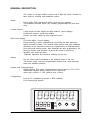
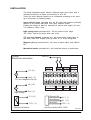
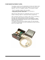
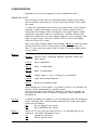
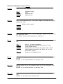
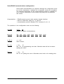
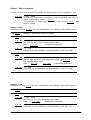
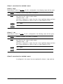
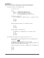
RUN
MAN
OUT1
OUT2
to20p
Counter / Totalizer / Ratemeter
Installation and user manual
rev. 2010-02
ARIAN S.A.
El Comendador 2340, Providencia, Santiago, Chile
Phone/Fax 4218333
www.arian.cl
PRELIMINARY INFORMATION
This document haves copyright reserved, C Arian INC.
Referred trademarks are of property of its respective owners.
ARIAN is registered by Arian S.A.
Technical help
If you find problems with the instrument, check its configuration to be
coherent with the application. If still it persists the problem, help can
obtain by the following media:
e-mail
[email protected]
phone/fax 56-2-4218333
web
www.arian.cl
Revision history
rev. 01/05
rev. 2010-02
First release.
Magnetic pickup input is incorporated.
GENERAL DESCRIPTION ......................................................................... 4
PART CODE .................................................................................................................... 5
TECHNICAL SPECIFICATIONS ..................................................................................... 6
INSTALLATION ........................................................................................... 7
Alarm outputs .................................................................................................................. 8
External reset inputs. ...................................................................................................... 8
Analog outputs (optional) ............................................................................................... 8
RS485 serial communications. (optional) ....................................................................... 8
Power supply ................................................................................................................... 8
Panel assembly ............................................................................................................... 8
CONFIGURATION FROM PC (RPS) .......................................................... 9
CONFIGURATION .................................................................................... 10
General Configuration menu ( O P E r ). ....................................................................... 11
Input configuration ........................................................................................................ 13
Alarms configuration. .................................................................................................... 15
Analog output configuration 4-20 mA. or 0-10V ............................................................ 17
Serial RS485 communications configuration. ............................................................... 19
OPERATION ............................................................................................. 20
Special reset functions. ................................................................................................. 20
Access to special functions and registers. .................................................................... 20
Sub-menu r E A d , examine parameter values. .......................................................... 21
Sub-menu F u n c , reset maximum, minimum, disabling outputs. ................................ 21
Modify alarms Set Points. ............................................................................................. 22
APPENDIX A ............................................................................................ 27
How to enter a number in floating point format from frontal buttons . ........................... 27
GENERAL DESCRIPTION
The To20p is a 6 digit totalizer counter and 4 digit rate meter. Suitable for
been used on counting and production control.
Inputs
-
Pulses NPN, PNP, Mechanical switch, High and low Voltages.
Two additional external inputs (dry contact) programmable as reset functions.
Counter display
6 High bright 14.5mm height red digits totalizer. (upper display)
Continuous memory, stores last reading.
Counter pre-scale, adjust for any engineering unit.
Rate meter display
Four 9mm digits. ( Lower display)
Pulses counting is done simultaneously measuring the time period between successive pulses. This method allows precise and quick readings
especially at low frequencies where the measurement is obtained mainly
from the period among pulses. Also simplifies the input programming, not
having to define “time windows” in which the count is carried out.
Separate rate meter pre-scale.
Registers maximum and minimum readings for the rate.
Alarms
-
Pre set values can be assigned to the totalized count or the rate.
Two output relays, with two programmable alarms each ( high and low)
Latch and standby functions.
Outputs and Communications
RS485 Modbus RTU serial communications reports data to a PC or PLC.
Galvanically isolated analog outputs for the rate meter,
active loop 4..20ma ,0...10V, passive loop 4..20ma.
Configuration.
-
From a PC compatible by means of RPS software.
From frontal push buttons.
RUN
MAN
OUT1
OUT2
User Manual to20p, rev.01/05, www.arian.cl
4
PART CODE
Defining a part number must be done selecting the following options.
Last 2 ones (-420A, -420L), -RS85 are optional that must not be included
if no required.
TO20P
-AC
-DC
-420A
-420L
-RS485
-AC :power supply 85...260 Vac, 6 W, 45...65 Hz.
-DC :power supply 18....60 Vdc, 6 W
OPTIONAL OUTPUT
-420L :4..20ma passive loop
-420A :4..20ma active, includes also 0..10Vdc
OPTIONAL
-RS485 :modbus RTU serial communications
For example:
TO20P-AC
to20p counter, AC power supply , without any optional output.
TO20P-DC-RS485
to20p counter, DC power supply and modbus RTU serial communications.
User Manual to20p, rev.01/05, www.arian.cl
5
TECHNICAL SPECIFICATIONS
INPUTS
Pulse inputs: NPN, PNP, Mechanical switch, TTL, High voltage (500 V) and magnetic
pickup (200mV AC min.)
Provides feeding for input sensor, +5, -7.5 Vdc, 30mA max.
Frequency range 0.01Hz ... 50KHz
DISPLAY
Allows engineering units with decimal places for totalized count and rate display.
Register max/min rate readings.
Counter: 6 digits Display (14mm), range 0...999999
Rate: 4 digits (9mm), range -999... 9999
ALARMS:
2 independent alarm outputs, each one with high and/or low alarm, with absolute or
relative set points.
Programmable alarm latch and "standby" that inhibits alarms when modifying set
points).
Can be assigned independently to the rate or counter.
OUTPUTS:
Relays, 2 outputs for alarms 250VAC/ 3A., normally open or normally close by software.
Optional:
-420L 4... 20 mA, loop powered, Vdrop 4.5V max. opto isolated (5kV).
-420A 4..20ma/0-10V Active loop, opto isolated (5kV).
-RS485 modbus RTU serial communications, opto isolated (5kV).
POWER SUPPLY:
Current mode switching power supply.
Versions:
85...260 Vac, 6 W, 45...65 Hz.
20...60 VDC, 6 W, (optional)
CONSTRUCTION:
Aluminum and Polycarbonate;
Total Dimension:
Panel cut:
Weight:
Operation temperature:
User Manual to20p, rev.01/05, www.arian.cl
IP65
DIN 1/8; 96 x 48 x 135 mm.
92 x 45 mm.
300 grams.
0 ... 50 °C.
6
INSTALLATION
The to20p ratemeter/counter admits 5 different input pulse types with a
maximum frequency of 50khz and minimum of 0.01 Hz.
There are some internal jumpers to be configured according to the input
type (see picture in following page)
Open collector input
switchs or any device
Feeding the sensor is
7.5v limited to 35mA
(terminals #11, #2, #1) used with inductive proximity
with NPN, PNP open collector output.
done by terminals #1 and #2 that supply +5v and max.
High voltage input (terminals #10 , #3) for pulses on the range
15V...500V. Can be AC pulse with cero cross.
TTL and low voltages (terminals #11, #3) need pulses higher than 3V
and lower than 50V. Voltage must go down to 1V to be recognized.
Magnetic pick up (terminals #11, #3) need a signal higher than 200mV
AC.
Mechanical switch (terminals #11, #2) used with relays or push-button.
TO20P
Electrical conections
Gnd (3)
ANALOG OUT
+
V
_
S1 (11)
Reset
Ex2 Ex1
RS-485
B
A
+5 -7.5 Gnd 90..260Vac
Sensor Supply P. SUP
Alimentación
OUT 1
RELE
Signal
HV S1
Gnd
+V
-I
+I
Gnd ( 3)
TTL and Magnetic Pick Up
+
V
_
HV (10)
Gnd ( 3)
OUT 2
RELE
High Voltage
S1 (11)
Brown/Cafe
Black/Negro
-7.5V ( 2)
Mechanical Switch
User Manual to20p, rev.01/05, www.arian.cl
Blue/Azul
+5V ( 1)
S1 (11)
-7.5V ( 2)
Inductive Switch NPN , PNP.
FID2019B
7
Configuración de Pines
NPN
PNP
TTL
Switch
Mecanico
Alto Voltage
200 mV
Mag. Pick Up
fid20_15b
Alarm outputs
Relays are the standard option for alarm outputs. As seen in the figure,
relay for alarm 1 (OUT 1) goes to terminals 6 and 7. The one for alarm 2
(OUT 2) to terminals 8 and 9, both are normally open outputs (NO).
Care must be taken on not exceeding the maximum relay current (3
Amp.), since they would be damaged quickly. Is recommended to use
fuses in series with the relays to protect them. Never use directly the
internal relay with the load. Always a external contactor should be used to
drive the final load.
External reset inputs.
The instrument haves 2 external inputs for connecting push buttons or
switchs. In the configuration menu is assigned a function to the inputs,
such reset total to cero, reset registered maximum and minimum.
Switchs are connected to terminals #12, #13 and #3 (Gnd)
Analog outputs (optional)
For isolating and retransmitting the measured variable to a PLC or another instrument. If this options are installed please refer to "analog output
configuration" chapter for details.
RS485 serial communications. (optional)
For communicating with PC or PLC using modbus RTU software protocol.
This is an isolated out that drives standard RS485 5Volts signals. If this
options are installed please refer to "RS485 communications configuration"
chapter for details.
Power supply
The instrument power supply is designed to operate with any voltage
between 90 and 260 volts without need of adjustment. (20VDC to 60VDC
for the DC power supply option). Once start up will continue operating
unless the network fall under 50 VAC. The instrument possesses an
internal 0.5Amp fuse that should be replaced with a similar one.
Panel assembly
Designed for panel assembly in a 92 x 45 mm. cut (Format DIN 1/8).
using clamps included with the instrument.
User Manual to20p, rev.01/05, www.arian.cl
8
CONFIGURATION FROM PC (RPS)
Two displays versions may be programmed by frontal push bottoms while
one display versions does not have push bottoms, so only can be programmed from a PC compatible computer. The following is needed:
- The PC compatible computer with vga monitor.
- RPS software (download latest version from www.arian.cl)
- Isolating interface cable. Part# RPS-C
While using the RPS system the configurating menus are the same described in following chapter for frontal push bottoms programming.
With de-energized instrument, the interface cable must be connected by
one side to the internal connector as shown in the picture.
The other side of the cable goes to the PC serial RS232 port (DB9).
Once done the connection the instrument must be energized and RPS
software executed in the PC.
The interface cable does optical isolation between PC and instrument.
Concluded the programming you must de-energized the device and then
plug off the interface cable.
User Manual to20p, rev.01/05, www.arian.cl
9
CONFIGURATION
Operation form must be programed on the configuration menu.
IMPORTANT NOTE:
Once entering on this menu the instrument stops counting input pulses
and will continue only when you exit the menu and returen to the operation mode.
To enter the configuration menu press the center button [•] and without
releasing it, press and release one time the "right or upper" button [^] .
Doing that, the message "KEY" will appear in the upper display. At this
moment the instrument asks for a access key. Now the number 2736
should be introduced in the lower display using the "left or lowering" and
"right or upper" button. Once the number 2736 is in the lower display,
press the button [•] to enter.
Now in the upper display appears the message M E n u. With the lateral
buttons select one of the 5 menus and to press center button [•] to
enter. To quit, select the option "SALi" or wait 16 seconds without pressing any button.
M E n u
O P E r.
General menu, configuring displays, operation modes and
other options.
I n P t.
input configuration.
A L - 1
alarm 1 configuration.
A L - 2
alarm 2 configuration.
4 - 20.
analog output, 0...10V, 4...20mA (if it is available)
r 4 8 5
rs485 serial communications.
S A L i
Returns to operation mode.
Once entering one of the menus, if no button is press in 16 seconds, the
devices returns automatically to operation mode.
At the end of each menu, always is asked if is desired to program the
new data and then to quit or continue configuring. These questions are
presented as:
P r o g
is asked if is desired to program or not the instrument with the introduced
values. Selecting "No", values recently placed will be erased and original
values will not change.
N o
Do not program new values.
S i
Set in EEPROM new values.
S A L i
Select “Si”
starting of
N o
S i
for quit (exit) the menu and “N o” for returning back to the
the actual configuration menu.
Continue in this menu.
Quit or exit the menu.
User Manual to20p, rev.01/05, www.arian.cl
10
General Configuration menu ( O P E r ).
d i s. b
Refers to the lower display.
o F F
r A t E
M A C S
M i n i
P.d i. b
Disabled Display.
Rate.
Maximum rate.
Minimum rate.
Places a fixed decimal point in the lower display to facilitate the viewing
engineering units.
-.
-.
-
-.
-
-
Without decimal point.
P.d i. A
Places a fixed decimal point in the 6 digit higher display to facilitate viewing engineering units.
The options are the same described for "display b".
E t r.1
A function is assigned to the external reset input 1, associated to terminal
#12.
o F F
r S t . N
r S t . A
d i . A L
r S t . C
there is no function assigned.
Reset registered maximum and minimum of rate.
Reset latched alarms.
Disable/restore momentarily the alarm relay outputs.
While disabled the alarms, the "RUN" led on front
panel blinks quickly.
Reset to cero totalized count.
E t r.2
A function is assigned to the external reset input 21, associated to terminal #13.
Options are the same described for previous case.
b o t . L
Special function set for the Lowering button [v] on the front panel. (the
left one).
Options are the same described for previous case.
b o t . H
Special function set for the "high" button [^] on the front panel (the right
one).
Options are the same of the previous one.
User Manual to20p, rev.01/05, www.arian.cl
11
F u . L c
= No,
Si
Special functions lock.
It should be set "Si", to restrict operator access to "F u n c" special
functions menu (e.g.. reset maximum, minimum, alarms, etc.) as described
in operation chapter.
P r o g
= No,
Si
Set "Si" for programming new data. Otherwise data will be lost when
quitting this menu.
S A L i
= No,
Si
Set “Si” for quitting this menu. Otherwise return back to its starting point.
User Manual to20p, rev.01/05, www.arian.cl
12
Input configuration
Previously must been set the input configurating pins (NPN, PNP, mechanical switch,..) as described in the installation chapter.
Ratemeter
The ratemeter measures frequency measurement by counting input pulses
and simultaneously measuring the period elapsed among them.
This method permits to obtain precise and quick readings specially for low
frequencies where the measurement is obtained mainly from the period
among pulses. At the same time simplifies input programming not having
to define "time windows" in which count is carried out.
For input calibration is required to set the instrument with the desired
reading Lx corresponding to a Fx frequency in Hz input pulses. That is
time constant to be multiplied to input frequency for obtaining the reading.
The ratemeter constant krAt is calculated by.
k.rAt = Lx / Fx
The division result must be in floating point format. In Appendix A is
described how to introduce floating point number from the frontal push
buttons. If you are using the RPS for configurating from a PC, then you
don't need to look appendix A.
For example in certain machine is desired to measure the turns by minute
(RPM) of an axe with 7 pulse by turn. Also you need the rate with 2
decimals of resolution.
If the axe is working at 1 RPM, then the reading considering the 2 decimals resolution must be Lx= 100 . Later you will set the decimal point to
look as 1.00.
At 1 RPM the sensor sends 7 pulses by minute then
Lx = 100
Fx = 7 / 1minute = 7 / (60seg) = 0.11666666 Hz.
k.rAt = Lx / Fx = 100/0.11666666 = 857.1428571
Totalizer
The totalizer haves an independent prescale. In the same form as the
rate a floating point constant will be multiplied to the accumulated number
of pulses to obtain the 6 digit reading.
[Reading] = k.c n t * [totalized pulses]
The constant is calculated as:
k.c n t = [Desired Reading] / [number of pulses for desired Reading]
User Manual to20p, rev.01/05, www.arian.cl
13
Using the same example of the axe sending 7 pulse by turn, let say that
for each turn are transported 25 Kg of a material to be totalized since the
last reset with 1 decimal resolution (100gr).
For finding the constant suppose the axe makes only 1 turn, sending 7
pulses. The reading must be 25.0 in this case.
The decimal point is set apart in the general menu, so reading is 250.
k.c n t = [Desired Reading] / [number of pulses for desired Reading]
k.c n t = [ 250] / [ 7 ] = 35.71428571
k. r A t
= floating point
Proportional constant between frequency input in Hz an the rate reading.
F I L t
= 1 ... 16
Corresponds to a time constant for filtering the rate reading. Internally
the instrument carries out a first order low pass filter calculation with time
constant "FILt". Can be set between 1 and 16 seconds.
Better you should leave this value set to 1 second, increasing it only if its
required by having noisy readings.
k. c n t
= floating point
Proportional constant between totalized reading and the totalized number
of pulses since last reset.
P r o g
= No,
Si
Set "Si" for programming new data. Otherwise data will be lost when
quitting this menu.
S A L i
= No,
Si
Set “Si” for quitting this menu. Otherwise return back to its starting point.
User Manual to20p, rev.01/05, www.arian.cl
14
Alarms configuration.
The to20p possesses 2 independent alarms (alarm-1 and alarm-2) each
one associated to a output relay (relay-1 and relay-2)
This alarms can be associated to the rate or to the totalized count readings independently.
Each one of the alarms (alarm-1 and alarm-2) haves 2 Set Points, high
and low. The alarm will activate when the input passes one of these limit.
Once the alarm condition is set, the upper display will operate intermittently indicating that this condition exists.
Both Set Points (high and low) for each alarm possess programmable
hysteresis and can be defined as absolute value or relative (displacement)
to a common Set Point.
Now is described the configuration for alarm-1.
Configuration of alarm-2 is similar.
ALAr
Selects the variable associated with alarm 1.
r A t E
rate
C n t r
totalized count
Depending on the selected option the alarm operation form varies.
Selecting C n t r disables Latch and Standby functions. Also will be not
available the d o n F option for high and low alarms.
When r A t E is selected, then the following parameters are required.
H i g h
High set point for alarm-1.
The parameters menu generated for each alarm type are described in the
operation chapter.
o F F
o n F h
d o n F
L o u
Disabled.
On/off with hysteresis high alarm. The alarm activates
when input is higher than a value programed in the
parameters menu.
Dual on/off type high alarm. The alarm activates when input
is higher than a value defined by general Set Point "SP. rE"
plus a displacement programed in the parameters menu.
Low set point for alarm-1.
o F F
o n F h
d o n F
Disabled.
On/off with hysteresis high alarm. The alarm activates
when input is lower than a value programed in the
parameters menu.
Dual on/off type high alarm. The alarm activates when input
is lower than a value defined by general Set Point "SP. rE"
minus a displacement programed in the parameters menu.
User Manual to20p, rev.01/05, www.arian.cl
15
L t c h
Enable Latch alarm.
If enabled, the alarm condition output will be maintained although the
condition that generated it disappears.
Operator must reset the latched alarm from the front panel.
No
disable
Si.
enable
S t b Y
The "standby" function inhibits alarm activation when the operator changes
the Set Point or the instrument is powered up.
If alarm condition is given in that situation, the activation of the alarm-1 is
inhibited until the condition that generates the alarm disappears.
After the condition that generates the alarm disappears (e.g.. the rate
reading arrived to the new set point) then the alarm is ready to be activated by normal operation.
No
disable
Si.
enable
r E L E
Is specified if the relay-1 will work normally open or normally closed. This
relay is active when alarm-1 condition exists.
d i r
Relay works direct , normally open.
i n v
Works inverted or normally closed.
P r o g
= No,
Si
Set "Si" for programming new data. Otherwise data will be lost when
quitting this menu.
S A L i
= No,
Si
Set “Si” for quitting this menu. Otherwise return back to its starting point.
User Manual to20p, rev.01/05, www.arian.cl
16
Analog output configuration 4-20 mA. or 0-10V
This output is optional although the configuration menu is in all instruments, hardware (the optional output board) could not be installed.
There are 2 analog output types, both optically isolated.
Option -420LP, is 4-20ma loop Powered that requires a voltage source in
series with the loop. Its typical use is conditioning and isolating process
variable for other instruments as e.g.. PLC or DCS.
Option -420AC, is 0-20mA, 4-20mA or 0-10V, active output. Its used to
send the selected variable to instruments whose input should be active
(powered) such as 0-10v or a 4-20ma loop powered valve.
Exists an internal jumper that must be placed depending on current or
voltage output (see figure in the following page)
The questions in the menu vary slightly according to board type installed.
Option -420LP
4 - 20
o F F
o n
Option -420AC
t Y P E
o
0
4
0
F F
- 2 0
- 2 0
- 1 0
Disable output.
enabled.
Disabled.
0 to 20 mA.
4 to 20 mA.
0 to 10 Volts.
V A r b
Asks by the variable that will be transmitted. See in the following page
the table for the possible analog output variables.
E. i n F
= -999... 9999
Introduce the value of the selected output variable for which the output
will deliver 4 mA. (or 0 Volts). For example if output for input temperature
was selected, when “E. i n F” = 0, the output will be 4 mA for zero degrees temperature. For lower temperatures the output will descended
down to 3.5 mA. aprox.
E. S u P
= -999... 9999
Introduce the value of selected output variable for which the output will
deliver 20 mA. (or 10volts). For the same example, place “E. S u P” =
1000, then the output will be 20 mA when temperature is 1000. For
higher temperatures the output will rise up to 20.5mA.
C ALi
This refers to output board calibration, is reserved for manufacturer use.
P r o g
= No,
Si
Set “Si” for programming new data. Otherwise data will be lost when
quitting this menu.
S A L i
= No,
Si
Set “Si” for quitting this menu. Otherwise return back to its starting point.
User Manual to20p, rev.01/05, www.arian.cl
17
+
-
Option -420AC
Salidas 4..20mA y 0..10V Activas
4...20mA and 0...10Volts active output
+
4.5V min.
+
ANALOG OUT
Gnd
+V
-I
+I
Opcion -420LP
Salida 4..20mA pasiva alimentada por Lazo
Loop powerd 4...20mA output.
0...10V
Para la salida activa, opcion -420AC
se debe colocar el PIN en una de
las dos posiciones según sea la
salida de corriente o voltaje
4..20mA
RS-485
B
A
PLC
For active output option -420AC,
internal jumper must be set.
420OUT_00
Possible analog output variables for the to20p
r A t e
Rate reading. This is the only option.
For example, setting:
E. i n F = 0,
The output is 4 mA for 0 rate reading.
E. S u P = 1000
The output is 20ma for rate 1000 reading. For higher reading output
saturates in 20.5ma
User Manual to20p, rev.01/05, www.arian.cl
18
Serial RS485 communications configuration.
Serial rs485 communications are optional, although the configuration menu
is in all the instruments, hardware for its operation could not be installed.
The command description for the communications protocol is available as
file in internet (www.arian.cl) and includes tag listing with its properties
and scales.
Characteristics : - RS485 physical protocol with optically isolated interface.
- start bit, 8 data bits, parity bit = 0, stop bit
- communication protocol, Modbus RTU ,functions 03, 06, 10
The questions in the configuration menu are the following.
n o d E
o F F , oN
Enable or disable communications.
b A u d
300, 600, 1200, 2400, 3600, 4800, 9600, 19.2k
Communication speed.
n. S c L
= 1...247
Slave number.
P r o g
= No,
Si
Set “Si” for programming new data. Otherwise data will be lost when
quitting this menu.
S A L i
= No,
Si
Set “Si” for quitting this menu. Otherwise return back to its starting point.
User Manual to20p, rev.01/05, www.arian.cl
19
OPERATION
The location of the front panel buttons can be seen in the figure. The
central button [•] is the main one, is used for selecting and entering
parameters. Lateral buttons are used to increase or decrease selected
parameter.
DISPLAY A
RUN
MAN
OUT1
OUT2
DISPLAY B
Activated alarm
Leds "OUT 1" and " OUT 2" reflect alarm relays state (activated or
desactivated) . Once an alarm (AL- or AL-2) is activated, the lower display
reading starts blinking (1 time/2 seconds) for advising the operator that a
alarm condition has occurred.
Special reset functions.
If these functions are enabled from the general configuration menu, is
possible to reset the maximums, minimum, latched alarms or disable
momentarily the relay outputs by pressing one of the front panel buttons
[^] or [v].
Access to special functions and registers.
For entering to the menu press the center button [•], immediately one of
2 submenus should be selected by means of the lateral buttons and
finally press again the center button [•] to enter the selected sub-menu.
r E A d
Examine parameters values.
F u n c
Reset functions and outputs disable.
While you are within this menus, the instruments continues counting input
pulses.
Following the content of each sub-menu is described.
User Manual to20p, rev.01/05, www.arian.cl
20
Sub-menu r E A d , examine parameter values.
This menu only permits to examine (not to modify) the values of some
internal parameters.
With lateral buttons you can scan parameters. Pressing central buttons
returns to normal operation mode.
r A t E
rate reading.
M AC S
Maximum registered rate.
M i n i
Minimum registered rate.
S P. r E
Shows general Set Point for alarms configured with relative set points.
Sub-menu F u n c , reset maximum, minimum, disabling outputs.
This menu can be locked from the configuration menu, in that case the
upper display shows the message L o c k .
Once entering this Sub-menu can be selected one of the following special
functions that will be executed immediately.
r S t . N
Resets registered maximum and minimum of PV.
r S t . A
Resets latched alarms.
d i . A L
Disables momentarily and enables the relay outputs.
If outputs are momentarily disabled by this function, the RUN led in front
panel blinks rapidly.
r S t . C
Resets ( returns to cero ) the totalized count.
Once a function is selected with the lateral buttons press central button
[•], and will be executed in the instantaneously and instrument returns
back to normal operation mode.
If no button is press in 16 seconds, the instruments exits menu.
User Manual to20p, rev.01/05, www.arian.cl
21
Modify alarms Set Points.
IMPORTANT NOTE
Once entering this menu the instrument stops counting input pulses and
will start counting again when you exit the menu.
To enter the menu press the center button [•] and without releasing it,
press and release one time the "right or upper" button [^] . Doing that, the
message "KEY" will appear in the upper display. At this moment the
instrument asks for a access key. Now the number 1234 should be
introduced in the lower display and then pressed the button [•] to enter.
The to20p possesses 2 independent alarms (AL-1 and AL-2) each one
associated to a output relay and can be linked to totalized count or rate.
Each alarm possesses a high and low set points.
When the measured variable is lower to the low set point or higher to
high set point, the alarm and its corresponding relay is activated.
For example the alarm-1, low has a set point SP.1L that can be obtained
in two different ways depending if it was configured as absolute (onFh) or
relative (donF) in the alarm configuration menu.
SP.1L = S P. r E SP.1L = 1. L . S P
1. L . d S
case donF
case onFh
ON
AL-1, baja
OFF
SP.1L - (1L.ht) /2
SP.1L
In the same way for high alarm-1 :
SP.1H = S P. r E + 1. H . d S
SP.1H = 1. H . S P
SP.1L + (1L.ht) /2
case donF
case onFh
ON
AL-1, alta
OFF
SP.1H - (1H.ht) /2
SP.1H
SP.1H + (1H.ht) /2
This menu is diferent depending if you have chosen to associate the
alarm to totalized count or rate also depends on the enabled options in
the configuration menu.
User Manual to20p, rev.01/05, www.arian.cl
22
Alarm-1, Rate associated.
If alarm AL-1 or AL-2 or both are enabled as relative alarms, the is required to set:
S P. r E
= -999,... 9999
General Set Point used in calculation of alarm operation point, only for
alarms configured as relative ( d o n F ) .
This parameter is asked only if some alarm was set as d o n F , other
case is omitted.
Alarm-1, High
According on value H i g h for AL-1 configuration, the following cases will be given :
Case o F F
Nothing is asked, high alarm is disabled.
Case onFh
1. H . SP = -999,... 9999
Set Point for AL-1 high. Becomes active when:
Rate > 1. H . SP
Considering hysteresis.
1. H . ht
= 0... 999
Hysteresis for the activation and desactivation of the AL-1 high.
Case donF
1. H . dS = -999,... 9999
Alarm-1 high activation point separation referred to S P. r E .
Will become active when:
Rate > S P. r E + 1. H . d S
Considering hysteresis.
1. H . ht
= 0... 999
Hysteresis for the activation and desactivation of the AL-1 high.
Alarm-1, Low
According on value L o w for AL-1 configuration, the following cases will be given :
Case o F F
Nothing is asked, low alarm is disabled.
Case onFh
1. L . SP = -999,... 9999
Set Point for AL-1 low. Becomes active when:
Rate < 1. L . SP
Considering hysteresis.
1. L . ht
= 0... 999
Hysteresis for the activation and desactivation of the AL-1 low.
User Manual to20p, rev.01/05, www.arian.cl
23
Case donF
1. L . dS = -999,... 9999
Alarm-1 low activation point separation referred to S P. r E .
Will become active when:
Rate < S P. r E - 1. L . d S
Considering hysteresis.
1. L . ht
= 0... 999
Hysteresis for the activation and desactivation of the AL-1 low.
User Manual to20p, rev.01/05, www.arian.cl
24
Alarm-2, Rate associated.
Alarm-2, High
Depending on value of H i g h for AL-2 configuration, the following cases will be given:
Case o F F
Nothing is asked, high alarm is disabled.
Case onFh
2. H . SP = -999,... 9999
Set Point for AL-2 high. Becomes active when:
Rate > 2. H . SP
Considering hysteresis.
2. H . ht
= 0... 999
Hysteresis for the activation and desactivation of the AL-2 high.
Case donF
2. H . dS = -999,... 9999
Alarm-2 high activation point separation referred to S P. r E .
Will become active when:
Rate > S P. r E + 2. H . d S
Considering hysteresis.
2. H . ht
= 0... 999
Hysteresis for the activation and desactivation of the AL-2 high.
Alarm-2, Low
Depending on value of L o w for AL-2 configuration, the following cases will be given:
Case o F F
Nothing is asked, low alarm is disabled.
Case onFh
2. L . SP = -999,... 9999
Set Point for AL-2 low. Becomes active when:
Rate < 2. L . SP
Considering hysteresis.
2. L . ht
= 0... 999
Hysteresis for the activation and desactivation of the AL-2 low.
Case donF
2. L . dS = -999,... 9999
Alarm-2 low activation point separation refered to S P. r E .
Will become active when:
Rate < S P. r E - 2. L . d S
Considering hysteresis.
2. L . ht
= 0... 999
Hysteresis for the activation and desactivation of the AL-2 low.
User Manual to20p, rev.01/05, www.arian.cl
25
Alarm-1 associated to totalized count.
Alarm-1, High
Depending on value of H i g h for AL-1 configuration, the following cases will be given:
Case o F F
Nothing is asked, high alarm is disabled.
Case onFh
Set Point for AL-1 high is active when:
Totalized count > SP
Set point is entered in 2 parts, first the 4 less significant digits and then
the 2 most significant in order to have a 6 digit number for SP.
1.H.S.4
= 0,... 9999
1.H.S.4
= 0,... 99
Alarm-1, Low
Depending on value of L o w for AL-1 configuration, the following cases will be given:
Case o F F
Nothing is asked, low alarm is disabled.
Case onFh
Set Point for AL-1 high is active when:
Totalized count < SP
Set point is entered in 2 parts, first the 4 less significant digits and then
the 2 most significant in order to have a 6 digit number for SP.
1.L.S.4
= 0,... 9999
1.L.S.4
= 0,... 99
Alarm-2 associated to totalized count.
Is configured in the same form as explained for Alarm-1, high and low.
User Manual to20p, rev.01/05, www.arian.cl
26
APPENDIX A
How to enter a number in floating point format from frontal buttons .
First write the number in the following format:
A. XXX YYY *10^ E
where,
A
XXX= B
YYY= C
E
one digit on the range -9 to + 9,
3 digits on the range 000 to 999,
the 3 following digits also 000 to 999
this is the exponent on the range -38 to 38.
Example, the number 1/70
1/70 = 0.014285714 = 1.4285714 *10^(-2) = 1. 428 571 4*10^ (-2)
A
B
C
E
=
=
=
=
1
428
571
-2
Another example, the number "pi" =3.141592, is put as:
A
B
C
E
=
=
=
=
3
141
592
0
Another example
-80.023467*10^3
:
-80.023467*10^3 = -8.0023467*10^4 = -8. 002 346 7*10^4
A = -8
B = 002
C = 346
E = 4
The instrument will request for the 4 integer numbers A, B, C, E
In the "display b" will show always the name of the parameter that is
entered, (e.g.. "k. rAt" )
In "display A" are set the numbers A, B, C, E in order.
The left digit will show the letter (A, b, C, E) indicating the integer to be
entered. In the last 3 digits is set the number.
Using the example for the number -8.0023467*10^4, the readings will be
"A. -8"
"b 002"
"c 346"
"E. 4"
User Manual to20p, rev.01/05, www.arian.cl
27