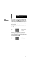
1
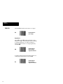
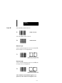
ALLEN-BRADLEY
Bulletin 2755
Hand-Held Scanner
with Wedge Option
(Catalog No. 2755-G3-W, 2755-G6-W)
User Manual
Important User
Information
Solid state equipment has operational characteristics
differing from those of electromechanical equipment.
“Application Guidelines for Application, Installation, and
Maintenance of Solid State Controls” (Publication
SGI-1.1) describes some important differences between
solid state equipment and hard–wired electromechanical
devices. Because of this difference, and also because of the
wide variety of uses for solid state equipment, all persons
responsible for applying this equipment must satisfy
themselves that each intended application of this
equipment is acceptable.
In no event will the Allen-Bradley Company be
responsible or liable for indirect or consequential damages
resulting from the use or application of this equipment.
The examples and diagrams in this manual are included
solely for illustrative purposes. Because of the many
variables and requirements associated with any particular
installation, the Allen-Bradley Company cannot assume
responsibility or liability for actual use based on the
examples and diagrams.
No patent liability is assumed by Allen-Bradley Company
with respect to use of information, circuits, equipment, or
software described in this manual.
Reproduction of the contents of this manual, in whole or in
part, without written permission of the Allen-Bradley
Company is prohibited.
Compaq is a registered trademark of Compaq Computer Corporation.
DEC and VT are registered trademarks of Digital Equipment Corporation.
Hewlett-Packard is a registered trademark of Hewlett-Packard Company.
IBM is a registered trademark of Internationa Business Machines Corporation
PC AT, PS/2 and PC XT are trademarks of International Business Machines Corporation
PHOTOSWITCH is a registered trademark of Allen-Bradley Company, Inc.
Table of Contents
Hand-Held Scanner with Wedge Option
A–B
Using
this Manual
Chapter 1
Overview
of Scanner
Chapter 2
Using
the Scanner
Chapter 3
Chapter Objectives . . . . . . . . . . . . . . . . . . . . . . . . . .
Contents of Package . . . . . . . . . . . . . . . . . . . . . . . . .
Intended Audience . . . . . . . . . . . . . . . . . . . . . . . . . . .
Overview of Manual . . . . . . . . . . . . . . . . . . . . . . . . .
Warning and Caution Symbols . . . . . . . . . . . . . . . .
Related Publications . . . . . . . . . . . . . . . . . . . . . . . . .
Chapter Objectives . . . . . . . . . . . . . . . . . . . . . . . . . .
Function of Scanner . . . . . . . . . . . . . . . . . . . . . . . . . .
Operating Modes . . . . . . . . . . . . . . . . . . . . . . . . . . . .
Hand-Held Mode . . . . . . . . . . . . . . . . . . . . . . . . .
Autosense Mode . . . . . . . . . . . . . . . . . . . . . . . . .
Setup Parameters . . . . . . . . . . . . . . . . . . . . . . . . . . . .
Keyboard Wedge . . . . . . . . . . . . . . . . . . . . . . . . .
General Setup . . . . . . . . . . . . . . . . . . . . . . . . . . .
Message Format . . . . . . . . . . . . . . . . . . . . . . . . . .
Symbology . . . . . . . . . . . . . . . . . . . . . . . . . . . . . .
Ordering a Scanner . . . . . . . . . . . . . . . . . . . . . . . . . .
Scanner Accessories . . . . . . . . . . . . . . . . . . . . . . . . .
Chapter Objectives . . . . . . . . . . . . . . . . . . . . . . . . . .
Physical Description . . . . . . . . . . . . . . . . . . . . . . . . .
LED Indicators . . . . . . . . . . . . . . . . . . . . . . . . . . . . . .
Safety Labels . . . . . . . . . . . . . . . . . . . . . . . . . . . . . . .
Scanning Ranges . . . . . . . . . . . . . . . . . . . . . . . . . . . .
Operating Scanner . . . . . . . . . . . . . . . . . . . . . . . . . . .
Beep . . . . . . . . . . . . . . . . . . . . . . . . . . . . . . . . . . . . . . .
Operating Tips . . . . . . . . . . . . . . . . . . . . . . . . . . . . . .
Troubleshooting . . . . . . . . . . . . . . . . . . . . . . . . . . . . .
1–1
1–1
1–1
1–2
1–3
1–3
2–1
2–1
2–2
2–2
2–2
2–3
2–3
2–3
2–4
2–4
2–5
2–6
3–1
3–1
3–2
3–3
3–4
3–6
3–7
3–7
3–8
i
Table of Contents
Hand-Held Scanner with Wedge Option
ii
Setup
Instructions
Chapter 4
General
Setup
Parameters
Chapter 5
Message
Format
Parameters
Chapter 6
Chapter Objectives . . . . . . . . . . . . . . . . . . . . . . . . . .
Installing Wedge Interface . . . . . . . . . . . . . . . . . . . .
Connecting Scanner Interface Cable . . . . . . . .
Removing Scanner Interface Cable . . . . . . . . .
Connecting Wedge Interface Cable . . . . . . . . .
Connecting Optional Power Supply . . . . . . . . .
Terminal Power Up Sequence . . . . . . . . . . . . . .
Enabling Wedge Mode . . . . . . . . . . . . . . . . . . . . .
Selecting a Terminal Type . . . . . . . . . . . . . . . . . . .
Scanner Configuration Guidelines . . . . . . . . . . . . .
Scanner Default Settings . . . . . . . . . . . . . . . . . . . . .
Resetting Factory Defaults . . . . . . . . . . . . . . . . . . . .
Chapter Objectives . . . . . . . . . . . . . . . . . . . . . . . . . .
System Status . . . . . . . . . . . . . . . . . . . . . . . . . . . . . . .
Power Consumption . . . . . . . . . . . . . . . . . . . . . . . . .
Beeper Operation . . . . . . . . . . . . . . . . . . . . . . . . . . . .
Capture Count . . . . . . . . . . . . . . . . . . . . . . . . . . . . . .
Spotter Beam . . . . . . . . . . . . . . . . . . . . . . . . . . . . . . .
Autosense Mode . . . . . . . . . . . . . . . . . . . . . . . . . . . . .
Chapter Objectives . . . . . . . . . . . . . . . . . . . . . . . . . .
Message Format . . . . . . . . . . . . . . . . . . . . . . . . . . . . .
Prefix . . . . . . . . . . . . . . . . . . . . . . . . . . . . . . . . . . . . . .
Suffix . . . . . . . . . . . . . . . . . . . . . . . . . . . . . . . . . . . . . .
Scanner Identifier . . . . . . . . . . . . . . . . . . . . . . . . . . . .
Code Identifier . . . . . . . . . . . . . . . . . . . . . . . . . . . . . .
Preamble or Postamble . . . . . . . . . . . . . . . . . . . . . . .
Preamble . . . . . . . . . . . . . . . . . . . . . . . . . . . . . . . . . . .
Postamble . . . . . . . . . . . . . . . . . . . . . . . . . . . . . . . . . .
Intercharacter Delay . . . . . . . . . . . . . . . . . . . . . . . . .
4–1
4–1
4–2
4–3
4–4
4–5
4–5
4–6
4–6
4–8
4–10
4–12
5–1
5–1
5–3
5–4
5–5
5–6
5–7
6–1
6–1
6–2
6–3
6–4
6–5
6–6
6–7
6–7
6–10
Table of Contents
Hand-Held Scanner with Wedge Option
Symbologies
Chapter 7
Chapter Objectives . . . . . . . . . . . . . . . . . . . . . . . . . .
Label Lengths . . . . . . . . . . . . . . . . . . . . . . . . . . . . . . .
Code 39 . . . . . . . . . . . . . . . . . . . . . . . . . . . . . . . . . . . .
Modulo 43 Check Character . . . . . . . . . . . . . . .
Transmit Stop/Start Characters . . . . . . . . . . . . .
Minimum Length . . . . . . . . . . . . . . . . . . . . . . . . .
Maximum Length . . . . . . . . . . . . . . . . . . . . . . . .
UPC (A and E) . . . . . . . . . . . . . . . . . . . . . . . . . . . . . .
Supplements . . . . . . . . . . . . . . . . . . . . . . . . . . . . .
Expanded UPC-E . . . . . . . . . . . . . . . . . . . . . . . .
Transmit Number System Digit . . . . . . . . . . . .
Transmit Check Digit . . . . . . . . . . . . . . . . . . . . .
UPC to EAN Translation . . . . . . . . . . . . . . . . . .
EAN/JAN . . . . . . . . . . . . . . . . . . . . . . . . . . . . . . . . . .
Supplements . . . . . . . . . . . . . . . . . . . . . . . . . . . . .
Transmit Number System Digit . . . . . . . . . . . .
Transmit Check Digit . . . . . . . . . . . . . . . . . . . . .
Interleaved 2 of 5 . . . . . . . . . . . . . . . . . . . . . . . . . . . .
Check Digit . . . . . . . . . . . . . . . . . . . . . . . . . . . . . .
Minimum Length . . . . . . . . . . . . . . . . . . . . . . . . .
Maximum Length . . . . . . . . . . . . . . . . . . . . . . . .
Standard 2 of 5 . . . . . . . . . . . . . . . . . . . . . . . . . . . . . .
Minimum Length . . . . . . . . . . . . . . . . . . . . . . . . .
Maximum Length . . . . . . . . . . . . . . . . . . . . . . . .
Code 128 . . . . . . . . . . . . . . . . . . . . . . . . . . . . . . . . . . .
Minimum Length . . . . . . . . . . . . . . . . . . . . . . . . .
Maximum Length . . . . . . . . . . . . . . . . . . . . . . . .
Codabar . . . . . . . . . . . . . . . . . . . . . . . . . . . . . . . . . . . .
Transmit Stop/Start Characters . . . . . . . . . . . . .
Minimum Length . . . . . . . . . . . . . . . . . . . . . . . . .
Maximum Length . . . . . . . . . . . . . . . . . . . . . . . .
7–1
7–1
7–2
7–3
7–3
7–4
7–4
7–5
7–5
7–5
7–6
7–6
7–7
7–8
7–8
7–9
7–9
7–10
7–10
7–11
7–11
7–12
7–12
7–12
7–13
7–13
7–13
7–14
7–14
7–15
7–15
iii
Table of Contents
Hand-Held Scanner with Wedge Option
Specifications
Chapter 8
Appendix A
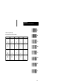
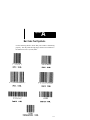
Bar Code Test Symbols
Appendix B
Digit Selection Symbols
Appendix C
Autosense Mode
Appendix D
Maintenance
Appendix E
Scanner Parameters
Glossary
Index
iv
Table of Contents
Hand-Held Scanner with Wedge Option
Figures
3.1
4.1
4.2
4.3
C.1
Scanning Ranges . . . . . . . . . . . . . . . . . . . . . . . . . . . .
Keyboard Wedge Interface Connections . . . . . . . .
Connecting Scanner Interface Cable . . . . . . . . . . . .
Removing Scanner Interface Cable . . . . . . . . . . . . .
Autosense Mode . . . . . . . . . . . . . . . . . . . . . . . . . . . . .
3–5
4–1
4–2
4–3
C–2
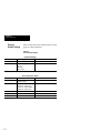
Tables
2.A
2.B
3.A
3.B
4.A
6.A
6.B
Wedge Interface Cables . . . . . . . . . . . . . . . . . . . . . .
Scanner Accessories . . . . . . . . . . . . . . . . . . . . . . . . .
LED Indicators . . . . . . . . . . . . . . . . . . . . . . . . . . . . . .
Scanning Ranges: Standard/Long Range Scanner
Scanner Default Settings . . . . . . . . . . . . . . . . . . . . .
Code Identifier Characters . . . . . . . . . . . . . . . . . . . .
Hexadecimal Conversion Table . . . . . . . . . . . . . . . .
2–6
2–6
3–2
3–4
4–10
6–5
6–8
v
Chapter
1
A–B
Using this Manual
Chapter
Objectives
This chapter gives an overview of the manual
including:
•
•
•
•
•
Contents
of Package
Contents of Package
Intended Audience
Overview of Manual
Warnings and Cautions
Related Publications
You should receive the following items when
ordering the Catalog No. 2755-G3-W or
2755-G6-W Scanner:
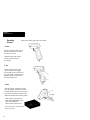
• Scanner
• Scanner Holder
• User Manual
Intended
Audience
No special knowledge is required to install,
configure, or operate the scanners as a keyboard
wedge interface. However, this manual does not tell
you how to use or generate an application program to
receive and store the data.
1–1
Chapter 1
Using this Manual
Overview
of Manual
1–2
This manual shows how to set up and use the scanner
as a keyboard wedge interface for non-contact scanning applications. The contents of each chapter are:
Chapter
1
2
Title
Using this Manual
Overview of Scanner
3
Using the Scanner
4
Setup Instructions
5
General
Setup Parameters
6
Message
Format Parameters
7
Symbologies
8
Specifications
Purpose
Provides an overview of this manual.
Gives an overview of scanner functions, operating modes, and scanner setup parameters.
Provides basic instructions on how to use the
scanner for non-contact scanning.
Shows how to setup the scanner as a
keyboard wedge interface and configure the
operating parameters of the scanner.
Covers parameters specific to the operation of
the scanner including beeper, power consumption, and capture count. Parameters are
selected by scanning bar code labels.
Covers parameters that control the format of
messages transmitted to the host computer or
terminal. Parameters are selected by scanning
bar codes.
Covers parameters that enable bar code
symbologies the scanner is capable of reading. Symbologies are disabled or enabled by
scanning bar codes.
Details specifications of the scanners.
Chapter 1
Using this Manual
Warning and
Caution Symbols
This manual contains the following caution and
warning symbols.
CAUTION:
A laser caution symbol that appears
where laser light is present.
WARNING:
!
A warning symbol means people might
be injured if procedures are not followed.
CAUTION:
!
Related
Publications
A caution symbol is used when equipment may be damaged if procedures are
not followed.
Below is a list of related publications you may need
to refer to when using the scanners.
• Publication No. 2755-921
Bar Code Basics
Describes bar code symbologies, equipment, and
typical applications.
• Publication No. 2755-2.44
Product Data for the family of
Visible Laser Diode Hand-Held Scanners
1–3
Chapter
2
A–B
Overview of Scanner
Chapter
Objectives
This chapter gives an overview of the scanner
including:
•
•
•
•
Function
of Scanner
Function of Scanner
Operating Modes
Scanner Setup Parameters
Scanner Accessories
The scanner is a keyboard wedge interface that is
capable of scanning, decoding, and transmitting bar
code data to a host computer or terminal.
As a keyboard wedge interface you can use the
scanner with most manufacturer’s terminals. The
scanner connects between the keyboard and display
of the terminal. In this mode the scanner draws
power directly from the terminal.
The wedge translates scanned data so that it appears
as if it was entered at the keyboard. When the wedge
is transmitting scanned data, the computer ignores
data entered at the keyboard.
You configure the scanner for keyboard wedge mode
by modifying scanner setup parameters. Parameters
are selected based on the terminal type and the types
of bar codes used in your application.
The scanner is easily configured by scanning the
appropriate bar code labels in Chapters 4 through 7 of
this manual. When a configuration label is scanned,
the scanner sends a 1 or 2 line acknowledgement
message to your terminal display.
Important: It is your responsibility to provide the
appropriate application program on the host
computer/terminal to receive and store the data.
2–1
Chapter 2
Overview of Scanner
Operating
Modes
The scanner functions in one of two operating modes:
Hand-Held Mode or Autosense Mode.
Hand-Held Mode
In hand-held mode, you hold the scanner in your
hand and press the trigger every time you want to
scan a bar code symbol.
Chapter 3 provides details on using the scanner in
hand-held mode.
Autosense Mode
In this mode the scanner operates in an optional
Autostand (Catalog No. 2755-NS2) for hands-free
operation. The scanner uses a low level laser beam as
an internal object sensor.
When the scanner is placed in the stand it becomes
immediately active for reading any bar code label
presented to it. The scanner is triggered when a bar
code label breaks the scan beam path (between the
reflector on the stand and the scanner).
You also have the option of removing the scanner
from the stand and using it as a conventional
hand-held scanner. The low level beam will not
interfere with hand-held use of the scanner.
When replaced in the stand the scanner reverts
automatically to the Autosense mode.
Note: Autosense mode can also be set up using a
PHOTOSWITCH reflector. See Accessories.
2–2
Chapter 2
Overview of Scanner
Setup
Parameters
The built-in setup parameters of the scanner fall into
four general categories:
•
•
•
•
Keyboard Wedge
General Setup
Message Format
Symbologies
Each category controls parameters that relate to
specific functions of scanner operations and its
operation in wedge mode.
Keyboard Wedge Parameters
Parameters that configure the scanner to operate in
keyboard wedge mode include:
• Enable Wedge Mode
• Select Terminal Type
Chapter 4 shows how to enable the scanner to operate
in wedge mode with a specific terminal type.
General Setup Parameters
General setup parameters are basic to the operation
of the scanner. These parameters control:
•
•
•
•
•
•
System Status Display
Power Consumption
Beeper Operation
Capture Count
Spotter Beam
Autosense Mode
General parameters are set by scanning bar code
labels in Chapter 5.
2–3
Chapter 2
Overview of Scanner
Message Format Parameters
Parameters that control the format and speed of
messages transmitted to the host include:
•
•
•
•
•
•
•
Prefix
Suffix
Scanner Identifier
Code Identifier
Preamble
Postamble
Intercharacter Delay
Message format parameters are enabled or disabled
by scanning bar codes in Chapter 6.
Symbology Parameters
The scanner can be configured to read the following
bar code symbologies:
•
•
•
•
•
•
•
Code 39
UPC
EAN/JAN
Interleaved 2 of 5
Standard 2 of 5
Code 128
Codabar
Symbologies are selected based on the requirements
of the application.
You enable or disable symbologies by scanning bar
codes in Chapter 7.
2–4
Chapter 2
Overview of Scanner
Ordering
a Scanner
The following figure shows the catalog number
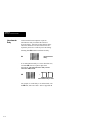
breakdown for ordering a scanner.
2755 - G 3 - W
Bulletin Number
Device
DeviceType
Type
G = Gun
Scan Range
3 = Standard Range
6 = Long Range
Decoder Type
W = Wedge
2–5
Chapter 2
Overview of Scanner
Scanner
Accessories
Table 2.A lists the wedge interface cables available
for the supported terminal types. Included with each
catalog number is an 8 foot (2.4 meter) coiled
scanner interface cable.
Table 2.A
Wedge Interface Cables
Catalog No.
2755-NC20
Terminal Description
IBM-PC, -XT, -AT
Allen-Bradley 6120, 6121
Alen-Bradley 1784-T35, -T50, -T60
Allen-Bradley 2706-DL40 (AT or XT Mode)
Compaq DeskPro, Compaq 286
2755-NC21
IBM PS/2 (50, 55, 60, 80)
Compaq 386
2755-NC22
IBM 3151, 3472
2755-NC24
DEC VT220, VT240, VT320, VT340,
VT420, VT1000
Requires Catalog No. 2755-PW1 Power Supply
1
1
Table 2.B lists other accessories for the scanners.
Table 2.B
Scanner Accessories
Catalog No.
2755-NS1
2755-NS2
2
3
2–6
Description
Scanner Holder (included with scanner).
Autostand 2
2755-GB1
Holster Belt
2755-GH5
Scanner Holster (functions on belt or sling)
2755-PW1
5V Power Supply, 110 VAC, 60 Hz
2755-NT1
Reflective Tape, 2 inch (50.8 mm) square
92-39 3
Circular Reflector, 3 inch (76.2 mm) diameter
3
92-47
Circular Reflector, 1 1/4 inch (31.8 mm) diameter
Reflective tape is supplied with Autostand. Additional reflective
tape is available by ordering Catalog No. 2755-NT1.
Allen-Bradley PHOTOSWITCH part number.
Chapter
3
A–B
Using the Scanner
Chapter
Objectives
This chapter covers some basic topics on the
operation and use of the scanner including:
•
•
•
•
•
•
•
•
Physical
Description
Physical Description
LED Indicators
Safety Labels
Scanning Ranges
Operating Scanner
Beep
Operating Tips
Troubleshooting
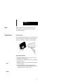
The scanners use a low power visible laser diode light
source for non-contact scanning applications.
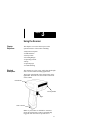
The trigger in the handle of the scanner turns on the
light beam. The beam exits the window on the front
of the scanner.
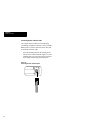
LED Indicators
Scanning Window
Trigger
Cable Connection
Note: If your scanner is enabled for Autosense
mode, the internal object sensor is automatically
triggered when bar codes are presented to it.
3–1
Chapter 3
Using the Scanner
Light, reflected off the bar code symbols, passes back
through the window and is detected by light sensors.
When a label is read, the laser is automatically turned
off until the next pull of the trigger.
The laser beam looks like a narrow red line of light. It
is actually a tiny spot of light traveling very fast. The
laser spot moves across the bar code symbol at
approximately 35 scans/second. The bar code is
scanned many times in a short period of time.
LED
Indicators
The rear of the scanner has two indicators that
provide a visual indication of scanner operation.
GOOD READ
SCANNING
Table 3.A defines the color and function of each
LED indicator.
Table 3.A
LED Indicators
3–2
LED Label
Color
GOOD READ
Green
SCANNING
Yellow
Function
The GOOD READ light momentarily turns on
(and you will hear a beep) when a bar code
symbol has been successfully decoded.
The SCANNING light turns on when the
device is scanning.
Chapter 3
Using the Scanner
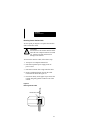
Safety
Labels
The scanners use a low power visible laser diode. As
with any bright light source, such as the sun, you
should avoid staring directly into the beam.
Momentary exposure to a CDRH Class II laser is not
known to be harmful.
The following figure shows the location of all safety
labels as they appear on the scanner.
CAUTION:
!
Use of controls, adjustments, or performance of procedures other than those
specified herein may result in hazardous
visible light exposure.
3–3
Chapter 3
Using the Scanner
Scanning
Ranges
The scanners can read bar code labels at various
distances depending on the bar code width (width of
narrowest element in bar code, either bar or space).
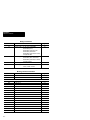
Table 3.B defines the scanning ranges for both the
standard and long range scanner. Scanning ranges are
listed for symbols with bar code widths from 6.0 mil
to 55.0 mil (.15 mm to 1.40 mm).
Table 3.B
Scanning Ranges: Standard and Long Range Scanners
Bar Code
Width
6.0 mil
(.15 mm)
7.5 mil
(.19 mm)
10.0 mil
(.25 mm)
15.0 mil
(.38 mm)
20.0 mil
(.51 mm)
40.0 mil
(1.02 mm)
55.0 mil
(1.40 mm)
Standard Range
(2755-G3-W)
3.0 in - 5.0 in
7.6 cm - 12.7 cm
2.5 in - 7.5 in
6.4 cm - 19.0 cm
1.0 in - 10.0 in
2.5 cm - 25.4 cm
1.5 in - 14.0 in
3.8 cm - 35.6 cm
2.5 in - 18.0 in
6.4 cm - 45.7 cm
9.0 in - 25.0 in
22.9 cm - 63.5 cm
12.0 in - 30.0 in
30.5 cm - 76.2 cm
Long Range
(2755-G6-W)
N.A.
N.A.
N.A.
8.0 in - 22 in
20.3 cm - 55.9 cm
12 in - 36 in
30.5 cm - 91.4 cm
23 in - 60 in
58.4 cm - 152.4 cm
23 in - 66 in
58.4 cm - 167.6 cm
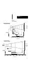
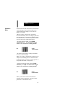
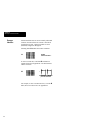
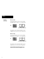
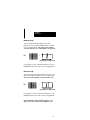
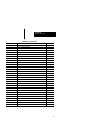
Figure 3.1 illustrates the scanning ranges in graphic
form. The figure shows that the scanning range of
the standard range scanner for a 40.0 mil (1.02 mm)
bar code width is 9.0 - 25.0 inches (22.9 - 63.5 cm).
The scanning range of the long range scanner for the
40.0 mil (1.02 mm) bar code width is 23 - 60 inches
(58.4 - 152.4 cm).
3–4
Chapter 3
Using the Scanner
Figure 3.1
Scanning Ranges
10
Standard Range Scanner
Catalog No. 2755-G3-W
5
Scanner
Width
of
Scanning
Beam
(inches)
0
0.006 in
(0.15mm)
5
0.0075 in
(0.19mm)
0.010 in
(0.25mm)
10
0.015 in
(0.38mm)
Narrow
Bar Width
0.020 in
(0.51mm)
0.040 in
(1.02 mm)
0.055 in
(1.40 mm)
0
inches
centimeters
5
12.7
10
25.4
15
38.1
20
50.8
25
63.5
30
76.2
Depth of Field
Long Range Scanner
Catalog No. 2755-G6-W
10
5
Width
of
0 Scanning
Beam
(inches)
5
Scanner
15.0 mil
(0.38 mm)
10
Narrow
Bar Width
20.0 mil
(0.51mm)
40.0 mil
(1.02 mm)
55.0 mil
(1.40 mm)
0
inches
centimeters
10
25.4
20
50.8
30
76.2
40
101.6
50
127.0
60
152.4
70
177.8
Depth of Field
3–5
Chapter 3
Using the Scanner
Operating
Scanner
Follow these basic steps to operate scanner.
1. Check
Before using the scanner, check
all cable connections to make
sure they are secure.
Chapter 4 defines the wedge
interface connections for
the scanner.
2. Test
Aim the scanner at the work
surface and press the trigger.
You should see the red beam on
the work surface, and the SCANNING indicator on the back of
the unit should be on.
2. Scan
Aim the scanner at the bar code and
press the trigger. Adjust the scanner
position so the beam is centered on the
bar code and overlaps it on both sides.
When the scanner has read the symbol:
• You will hear a beep and/or ...
• The GOOD READ light will
turn on momentarily.
• The red beam will turn off.
If you fail to scan, see the Troubleshooting section.
3–6
Chapter 3
Using the Scanner
Beep
When scanning a bar code symbol, listen for one
short, high tone. It means the bar code has been
decoded successfully.
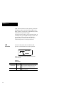
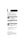
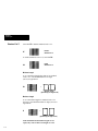
Operating Tips
Hold at an Angle
Do not hold the scanner directly over the bar code. In
this position light can bounce back into the scanner
and prevent decoding. Angle the scanner slightly.
Scan the Entire Symbol
• Move the scanner so the beam crosses every bar
and space on the symbol.
• The larger the symbol the farther away you should
hold the scanner.
RIGHT
• Hold the scanner closer for symbols with bars that
are close together.
• If you have difficulty reading a label hold the
scanner beyond the recommended range in Figure
3.B and then move the scanner closer.
WRONG
3–7
Chapter 3
Using the Scanner
Troubleshooting
This section provides a list of things to check if you
are having problems scanning.
Note: Scanning problems are most often caused
by poor quality bar code symbols. If scanning
problems arise test your bar code system using the
high quality bar code test symbols supplied in
Appendix A.
• Make sure the scanner is configured to read the
the type of bar codes you are trying to scan.
• Check if the bar code symbol is worn or damaged.
• Verify that you are holding the scanner at an angle.
• Make sure the beam crosses every bar and space
on the symbol.
• Check for loose cable connections.
• Check that there is power to the scanner and the
host computer or terminal.
If you perform these checks and the symbol still does
not scan, contact your Allen-Bradley representative.
3–8
Chapter
4
A–B
Setup Instructions
Chapter
Objectives
This chapter provides setup instructions including:
•
•
•
•
•
Installing
Wedge Interface
Installing the Wedge Interface
Enabling Wedge Mode
Selecting Terminal Type
Scanner Configuration Guidelines
Scanner Default Settings
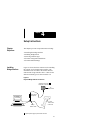
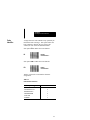
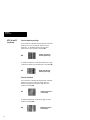
Figure 4.1 shows the basic connections for installing
the scanner as a keyboard wedge interface. The
installation uses two cables: the scanner interface
cable and the wedge interface cable. Cables for the
different terminal types are listed in Table 2.A.
Figure 4.1
Keyboard Wedge Interface Connections
Optional Power Supply
Catalog No. 2755-PW1
1
AC
Power Source
Power Supply
Receptacle
Computer
or Terminal
Wedge
Interface Cable
1
Scanner
2755-G3-W or
2755-G6-W
Optional power supply required for DEC terminals.
4–1
Chapter 4
Setup Instructions
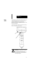
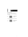
Connecting Scanner Interface Cable
The scanner interface cable has a modular plug
(resembling a telephone connector) on one end and a
DB9 squeeze-to-release connector on the other end.
To install the interface cable:
Insert the modular plug into the opening at the
bottom of the scanner’s handle (Figure 4.2). The
modular plug is keyed to insure proper insertion.
Press firmly until the plug clicks into place.
Figure 4.2
Connecting Scanner Interface Cable
4–2
Chapter 4
Setup Instructions
Removing Scanner Interface Cable
At some point you may have to replace the interface
cable with another cable.
CAUTION:
!
Do not remove the scanner interface cable
until the host computer/terminal is turned
off. Failure to do this could result in
damage to the scanner.
To remove the interface cable, follow these steps.
1. Turn power to computer/terminal off.
2. Disconnect optional power supply from AC
power source.
3. Disconnect scanner from wedge interface cable.
4. Insert a straightened paper clip into the cable
release hole as shown in Figure 4.3.
5. Press down firmly on the paper clip to release the
retainer and gently pull the connector out of the
scanner.
Figure 4.3
Removing Interface Cable
Cable Release Hole
4–3
Chapter 4
Setup Instructions
Connecting Wedge Interface Cable
The wedge interface cable connects the scanner to the
terminal keyboard and the terminal. You select a
wedge interface cable based on the the terminal you
are using. The available cables are listed in Table 2.A.
The wedge interface cable has a connector housing
and a ”Y” cable. The housing contains 1 or 2
plug-in sockets for the scanner and an optional power
supply. The two legs of the ”Y” cable connect to the
terminal keyboard and the terminal.
CAUTION:
!
Do not connect scanner to terminal until
power to the terminal is off. Failure to do
this could result in damage to the scanner.
To connect the wedge interface cable:
1. Turn off power to the computer/terminal to which
the scanner will be connected.
2. Plug the DB9 squeeze-to-release connector
of the scanner interface cable into the
connector housing of the wedge interface cable.
3. Unplug the keyboard from the terminal and replug
the keyboard into the short leg of the ”Y” cable.
4. Plug the remaining long leg of the ”Y” cable into
the terminal where the keyboard was connected.
5. Arrange the fully connected unit so that all cables
run freely.
4–4
Chapter 4
Setup Instructions
Connecting Optional Power Supply
Some terminal interfaces require an external power
supply. One end connects to a standard AC
receptacle supplying the appropriate voltage level.
The other end plugs into a receptacle located on the
housing connector of the wedge interface cable.
CAUTION:
!
The Catalog No. 2755-PW1 Power Supply
has the following polarity:
+5 V +
Ground
If using another power supply, the polarity
must be the same.
To install the power supply:
1. Power to the terminal must be turned off.
CAUTION:
!
Do not connect power supply until the
terminal is turned off. Failure to follow
this caution could result in damage to the
scanner or terminal.
2. Plug the circular connector of the power supply
into the receptacle on the housing connector of
the wedge interface cable.
3. Plug the power supply into a standard AC
power source.
Terminal Power Up Sequence
Turn on the power to the terminal to which the
scanner is connected. The unit will issue a series of
beeps which are intentional and indicate that the
terminal/keyboard power-on reset routines have
been completed.
4–5
Chapter 4
Setup Instructions
Enabling
Wedge Mode
After installing the keyboard wedge interface you
need to enable the scanner to operate in wedge mode.
If this is a first time installation you must enable
the scanner to operate in wedge mode.
To enable wedge mode, scan label CE and listen for
two short beeps.
CE
Selecting a
Terminal Type
Enable
Wedge Mode *
You now need to identify the type of terminal that the
wedge interface is connected to. Scan the appropriate
label below and listen for two short beeps.
First time installations require you to program the
scanner for use with the connected terminal.
CF
CG
1
2
4–6
PC-AT *
PS/2 and 50/60/80
Allen-Bradley 6121
Allen-Bradley 1784-T50, -T60
Allen-Bradley 2706-DL40 1
Allen-Bradley 1784-T35 (AT mode)
Compaq 386, 286
2
PC-XT
Allen-Bradley 6120, 2706-DL401
Allen-Bradley 1784-T35 (XT mode) 2
Compaq Deskpro
Can be used in AT or XT mode depending on the internal jumper. See DL40 User Manual.
Can be used in AT or XT mode depending on the DIP switch setting. See User Manual for 1784-T35.
Chapter 4
Setup Instructions
CH
CI
IBM 3151,
3472
DEC VT220
VT240, VT320, VT340,
VT420, VT1000
You have now completed the process of installing and
configuring the scanner to operate in wedge mode.
The rest of the manual covers additional
parameters that can be set for the scanner and
your application. Review the configuration
guidelines and factory default settings in the
following sections to determine if changes are
required.
4–7
Chapter 4
Setup Instructions
Scanner
Configuration
Guidelines
Configuration is the process of enabling or disabling
certain scanner operating parameters. The host
computer/terminal and the types of bar codes that will
be encountered will determine which parameters
should be enabled or disabled.
Follow three basic steps to configure your scanner:
1. Review the rest of the manual to familiarize
yourself with each group of scanner parameters.
2. Review the requirements of your application
This will enable you to determine if the factory
defaults must be changed.
3. Enable or disable the relevant parameters by
scanning the bar codes in Chapters 4 through 7.
The section that follows describes this process.
All configuration bar code labels in this manual
are Code 128, Character Set B.
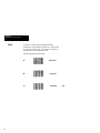
Scanning Menu Labels
The scanner does not have a distinct configuration
mode. Instead, it automatically recognizes and reacts
to labels you scan. You do not scan an enter or exit
label to begin or exit configuration mode.
Most parameters are set by scanning one label. For
example, assume your application uses Codabar
labels. By default, this symbology is disabled.
To select the Codabar symbology, locate the Codabar
menu in Chapter 7 and scan the label to the left of
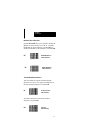
Enable Codabar. The correct label is shown below.
VB
Enable
Codabar
A successful scan is indicated by two short-high
beeps. An unsuccessful scan produces no beeps
and requires you to rescan the Codabar label.
Most parameters are modified in this way. When you
are finished with modifications you can resume
normal bar code scanning.
4–8
Chapter 4
Setup Instructions
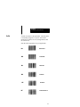
Note: When enabling or disabling a parameter, be
sure the scanner beam illuminates only one symbol at
a time. The layout of this manual minimizes the
accidental scanning of multiple labels.
Some parameters require that you scan multiple
labels to modify a setting. An example is the
Intercharacter Delay parameter. To set the
intercharacter delay to 5 milliseconds (msec):
1. Scan the Intercharacter Delay (GB) label and
listen for one short beep.
GB
+
Intercharacter Delay=xx msec
The dotted boxes to the right of the label indicate
that you must scan two additional labels; one for
the digit 0 and the second for the digit 5.
2. After the beep, scan the bar code beside 0 in
Appendix B, and listen for one short-high beep.
3. Scan the bar code beside 5 in Appendix B and
listen for two short beeps. The two beeps indicate
that you scanned the last parameter argument.
If you scan the Intercharacter Delay (GB) label and
then scan a normal data label (instead of 0 and 5), a
normal tone is emitted in response to the data label,
and the programming command is ignored. No exit
code is required to resume normal operations.
Note: Any parameter that requires multiple scans
will display dotted boxes to the right of the primary
label. The number of dotted boxes indicates the
number of additional labels to be scanned.
4–9
Chapter 4
Setup Instructions
Scanner
Default Settings
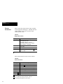
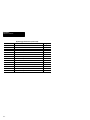
Table 4.A lists the factory default settings for each
group of scanner parameters.
Table 4.A
Scanner Default Settings
Parameter
Wedge Mode
Terminal Type
Parameter
Power Consumption
Beeper Operation
Capture Count
Spotter Beam
Autosense Mode
4–10
Keyboard Wedge
Options
Default
Enable or Disable
Enable
PC-AT, PS/2, 50/60/80
PC-AT, PS/2, 50/60/80
PC-XT
IBM 3151
DEC VT220
General Scanner Setup
Options
Default
Enable Continuous Full Power Continuous Full Power
Enable Standby
Beeper Off
Beeper On; Volume Loud
Beeper On; Volume Low
Beeper On; Volume Medium
Beeper On; Volume Loud
1 or 2
1
Enable or Disable
Disable
Enable or Disable
Disable
Chapter 4
Setup Instructions
Table 4.A (continued)
Scanner Default Settings
Parameter
Prefix
Suffix
Scanner Identifier
Code Identifier
Preamble
Postamble
Intercharacter Delay
Code
Code 39
UPC (A and E)
Message Format
Options
None, STX, or SOH
None, ETX, CR, LF, HT, or
CR and LF
Disable or a number (01- 99)
Disable or Enable
None or 1-4 characters
None or 1-4 characters
User Defined Delay (in msec) or
No Intercharacter Delay
Default
None
None
Disable
Disable
None
None
No Intercharacter Delay
Symbologies
Options
Disable
Enable Standard Code 39
Enable Full ASCII Code 39
Default
Enable Standard Code 39
Enable or Disable Modulo 43
Check Character
Enable or Disable Transmission
of Start/Stop Character
Minimum Length
Maximum Length
Disable
Enable with 2 or 5 digit supplements
Enable without 2 or 5 Digit Supplements
Disable
Enable/Disable Expanded UPC-E
Enable/Disable Transmission
of Number System Chararacter
Enable/Disable Transmission
of Check Digit
Enable/Disable UPC to EAN Translation
Disable
Enable
Disable
1
32
Enable without 2 or 5
Digit Supplements
Enable
Disable
4–11
Chapter 4
Setup Instructions
Table 4.A (continued)
Scanner Default Settings
Code
EAN/JAN (8 or 13 digit)
Interleaved 2 of 5
Standard 2 of 5
Code 128
Codabar
Resetting
Factory Defaults
Symbologies
Options
Disable
Enable with 2 or 5 Digit Supplements
Enable without 2 or 5 Digit Supplements
Default
Disable
Enable or Disable Transmission
Number System Chararacter
Enable or Disable Transmission
of Check Digit
Disable
Enable without Check Digit
Enable with Check Digit
Enable
Minimum Length
Maximum Length
Enable or Disable
Minimum Length
Maximum Length
Enable or Disable
Minimum Length
Maximum Length
Enable or Disable
Enable or Disable Transmission
Number System Chararacter
Minimum Length
Maximum Length
2
32
Disable
4
32
Enable
1
32
Disable
Disable
Enable
Disable
1
32
To reset the scanner to the factory default settings
(listed in Table 4.A) scan label ZA.
ZA
Reset to
Factory Defaults
Note: Scanning this label produces a bi-level tone.
4–12
Chapter
5
A–B
General Setup Parameters
Chapter
Objectives
This chapter describes parameters specific to the
operation of the scanner including:
•
•
•
•
•
•
System Status
Power Consumption
Beeper Operation
Capture Count
Spotter Beam
Autosense Mode
To set specific operating parameters, scan the
appropriate bar code labels in each section.
Note: Throughout this chapter, default settings for
parameters are flagged by an asterisk (* ).
System
Status
The labels in this section allow you to examine the
configuration of your system.
To send a list of currently programmed parameters to
the display device, scan option ZB. A sample display
is shown on the top of the next page.
Note: Scanning ZB may interfere with your terminal
software, depending on your application.
ZB
Display Configuration
5–1
Chapter 5
General Setup Parameters
Display Configuration Example (ZB Command)
Power
Data Bits
Char Delay
Scanner ID
Preamble
Code ID Char
Serial Buffr
Always On
7
00
None
None
No
Full
Parameter
39
*Armed
Yes
ASCII
No
*Addendum
–
Xmit S/S
No
Check Ch
No
Send Sys #
–
Send Ck Ch
–
UPCE Expand –
Limits
01–32
UPC
Yes
–
No
–
–
Yes
Yes
No
–
Model
5317
Beeper
Loud
Parity
None
Protocol Off
Prefix
Off
Postamble None
Labels
Full
Display
Duplex Half
Symbology
EAN I 2/5
No
No
–
–
No
–
–
–
–
No
Yes
–
Yes
–
–
–
– 02–32
S 2/5
128
No
Yes
–
–
–
–
–
–
–
–
–
–
–
–
–
–
04–32 01–32
Version
Baud Rate
Stop Bits
RTS
Suffix
* Redundant Scan
Label Delay
Auto Label Bfr
2.51
9600
1
Rcv Rdy+
Off
No
00
Off
Codabr
No
–
–
No
–
–
–
–
01–32
* Redundant Scan=Capture Count, Armed=Enabled, Addendum=Supplements
Shaded parameters are not supported in this product.
Scan option ZC to send the program version number
followed by carriage return-line feed (CR-LF) to the
display device. The version number is sent in the
form ##.## (1.00, for example).
ZC
Transmit Version Number
Scan option @C to send an identification code which
verifies the specific program type of the scanner to
the display device.
@C
Transmit Program ID
Note: Options ZC and @C are used for
troubleshooting to identify the scanner.
5–2
Chapter 5
General Setup Parameters
Power
Consumption
You can select one of two power consumption modes
for the scanner. Option @A supplies full power to the
scanner at all times. Option @B allows the scanner to
revert to standby mode after a successful read. This
mode is a power conservation feature whereby the
scanner uses extremely low power (microwatts) from
the host terminal.
To supply full power to the scanner at all times, scan
label @A.
@A
Enable Continuous
Full Power *
Note: The scanner automatically uses full power
when configured to operate in Autosense mode.
To allow the scanner to revert to standby mode after a
successful read, scan label @B.
@B
Enable
Standby Power
5–3
Chapter 5
General Setup Parameters
Beeper
Operation
To disable or set the volume of the beeper, scan the
appropriate option below.
AA
5–4
Beeper Off
AB
Beeper On;
Volume Low
AC
Beeper On;
Volume Medium
AD
Beeper On;
Volume Loud *
Chapter 5
General Setup Parameters
Capture
Count
Capture Count determines the number of successful,
identical decodes that must occur for a valid read.
You can use the capture count to enhance the security
of the bar code reader.
Option BC sets the capture count to 1 which requires
one successful decode.
BC
Capture Count = 1 *
Scan option BD to set the capture count to 2. Two
identical decodes must occur for a valid read.
BD
Capture Count = 2
Because the laser scans a label many times a second,
you will notice little or no change in the speed of the
decode.
5–5
Chapter 5
General Setup Parameters
Spotter Beam
You can enable the scanner to use a spotter beam
which helps when aiming the scanner. Each time you
press the trigger, the scanner generates a bright laser
spot for a fixed duration, after which the scanner
beam is activated.
The spotter beam is recommended for long range
applications.
Scanning label NP disables the spotter beam. Hold
the trigger for two seconds after scanning.
Disable
Spotter Beam *
NP
To enable the spotter beam, scan label NQ, then scan a
digit from 0 – 9 (Appendix B), holding the trigger
for two seconds after scanning the digit. Each
digit enables the spotter beam for a specified duration
as shown in the table below. For example, to enable
the spotter beam for 200 milliseconds, scan the NQ
label, then scan code 3 in Appendix B.
NQ
+
Enable Spotter Beam=xx msec
This Digit
0
1
2
3
4
5
6
7
8
9
Enables Spotter Beam for:
50 ms
100 ms
150 ms
200 ms
250 ms
300 ms
350 ms
400 ms
450 ms
500 ms
Note: Spotter Beam and Autosense Mode are
mutually exclusive parameters. Only one of these
parameters can be enabled at a time.
5–6
Chapter 5
General Setup Parameters
Autosense
Mode
In Autosense mode, the scanner has an internal object
sensor allowing you to operate the scanner in an
optional Autostand (Catalog No. 2755-NS2) for
hands-free operation.
When the scanner is placed in the Autostand it
becomes immediately active for reading any bar code
label presented to it. The scanner is triggered when a
bar code label breaks the scan beam path between the
reflective label on the stand and the scanner.
To activate Autosense mode, scan the Enable
Autostand (NO) label. You must hold the trigger
down for two seconds after scanning the label.
NO
Enable
Autosense Mode
The scanner will respond by emitting a continuous,
low level, red beam of light.
Note: The scanner is automatically configured to use
full power (not standby power) in Autosense mode.
For details on how to set up the scanner to operate in
the optional Autostand, see Appendix C.
To deactivate Autosense mode, scan the Disable
Autostand symbol (NN). You must hold the trigger
down for two seconds after scanning the label.
NN
Disable
Autosense Mode *
Note: Spotter Beam and Autosense Mode are
mutually exclusive parameters. Only one of these
parameters can be enabled at a time.
5–7
Chapter
6
A–B
Message Format Parameters
Chapter
Objectives
This chapter defines parameters that control the
format of transmitted bar code messages including:
•
•
•
•
Prefix and Suffix
Scanner Identifier
Code Identifier
Preamble and Postamble
In addition to these parameters, you can program an
intercharacter delay to prevent data overruns with
your host computer/terminal or wedge.
Message
Format
Prefix
Scanner Identifier
A message transmitted from the scanner upon a
successful decode has the following format:
Preamble
Code Identifier
Data
Postamble
Suffix
Some of these message parameters may not be
required or may vary from one host system to
another. You select parameters based on the
requirements of your application and the host system.
To select message parameters, you scan the
appropriate bar code labels in each section.
Note: Throughout this chapter default settings for
parameters are flagged by an asterisk (*).
6–1
Chapter 6
Message Format Parameters
Prefix
A prefix is a subset of the preamble normally
formatted to some industry standard. It is represented
by a specific ASCII code. An example of a prefix is
the STX (Start of Transmission) code.
Scan the appropriate prefix label.
6–2
IA
Prefix=None *
IB
Prefix=STX
IC
Prefix=SOH
Pref
Chapter 6
Message Format Parameters
Suffix
A suffix is a subset of the postamble. Like the prefix,
it is normally assigned to a specific ASCII code.
Examples of suffixes are CR (Carriage Return) and
LF (Line Feed).
Scan the suffix appropriate for your application.
MA
Suffix=None *
MB
Suffix=ETX
MC
Suffix=CR
MD
Suffix=LF
ME
MF
Suffix=HT
Suffix=CR and LF
6–3
Chapter 6
Message Format Parameters
Scanner
Identifier
Scanner ID characters are used to identify individual
scanners when more than one scanner is interfaced
with the host system. Options available are none
(Disabled) or digits 01 through 99.
Scanning label JA disables the scanner identifier.
JA
Disable
Scanner Identifier *
To enter a scanner ID, scan label JB and then two
separate digits from Appendix B. The ID characters
cannot exceed 99.
JB
+
Enable Scanner Identifier
plus two characters
For example, to enter a scanner ID of 01, scan the JB
label, then scan codes 0 and 1 in Appendix B.
6–4
Chapter 6
Message Format Parameters
Code
Identifier
A single-character code identifier may optionally be
transmitted with a message. This option allows the
host computer to identify the type of bar code
scanned, as well as the encoded information.
Scan option FA to disable the code identifier.
FA
Disable
Code Identifier *
Scan option FB to enable the code identifier.
FB
Enable
Code Identifier
Table 6.A shows the code identifier character
assignments.
Table 6.A
Code Identifier Characters
Symbology
Code 39
Interleaved 2 of 5
Standard 2 of 5
UPC/EAN/JAN
Code 128
Codabar
Code Identifier
a
b
c
d
f
h
6–5
Chapter 6
Message Format Parameters
Preamble
or Postamble
Preambles and postambles consist of up to four
ASCII characters. Each ASCII character is encoded
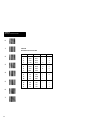
as two hexadecimal characters. Use Table 6.B,
Hexadecimal Conversion Table, to look up the
hexadecimal equivalent.
To use the conversion table:
1. Find each ASCII character in the table and locate
the corresponding bold hexadecimal equivalent
character in the top row and the left column of the
table. For example, the ASCII character ”Q” is
represented by the hexadecimal numbers 5 (top)
and 1 (left).
2. Scan the bar code symbols that correspond to the
hexadecimal equivalent characters. First scan the
bar code symbol that corresponds to the bold hex
character at the top. Then scan the bar code
symbol that corresponds to the bold hex character
at the left.
For example, for the ASCII character ”Q”, first
scan the bar code symbol labeled 5, then scan the
bar code symbol labeled 1. If your preamble or
postamble contains an ”N”, first scan 4 and then E.
3. Repeat this procedure for each ASCII character
you want to enter.
Note: If you select a preamble or postamble you
must scan four ASCII characters, even if the
preamble or postamble is less than four characters in
length. Do this by scanning null (NUL) characters
for the additional characters.
For example, if your preamble is ”AB” (in ASCII
code), enter A, B, and two null characters by
scanning the hexadecimal characters 4,1 4,2 0,0 0,0.
Because each ASCII character is represented by two
hexadecimal characters, you need eight scans.
6–6
Chapter 6
Message Format Parameters
Preamble
A preamble is a string of characters that prefixes a
message that is transmitted to the host. The preamble
may be used to identify the scanner that sent the
message. The maximum preamble length is four
ASCII characters.
KA
Preamble=None *
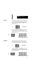
To enter a preamble, scan the KB label, then refer to
Table 6.B to enter the four ASCII characters. The
procedure on the previous page explains how to enter
preamble characters.
+
KB
Preamble = 4 ASCII (8 Hex) characters
Postamble
A postamble is similar to a preamble, except it is
appended to the message which is transmitted to the
host. Its maximum length is four ASCII characters.
LA
Postamble=None *
To enter a postamble, scan the LB label, then refer to
Table 6.B to enter the four ASCII characters. The
procedure on the previous page explains how to enter
preamble characters.
LB
+
Postamble = 4 ASCII (8 Hex) Characters
6–7
Chapter 6
Message Format Parameters
0
1
2
3
4
5
6
7
6–8
Table 6.B
Hexadecimal Conversion Table
0
1
2
3
4
5
6
7
8
9
A
B
C
D
E
F
0
NUL
SOH
STX
ETX
EOT
ENQ
ACK
BEL
BS
HT
LF
VT
FF
CR
SO
SI
1
DLE
DC1
DC2
DC3
DC4
NAK
SYN
ETB
CAN
EM
SUB
ESC
FS
GS
RS
US
2
SP
!
”
#
$
%
&
’
(
)
*
+
,
–
.
/
3
0
1
2
3
4
5
6
7
8
9
:
;
<
=
>
?
Chapter 6
Message Format Parameters
8
Table 6.B (continued)
Hexadecimal Conversion Table
9
0
1
2
3
4
5
6
7
8
9
A
B
C
D
E
F
4
@
A
B
C
D
E
F
G
H
I
J
K
L
M
N
O
5
P
Q
R
S
T
U
V
W
X
Y
Z
[
\
]
^
_
6
‘
a
b
c
d
e
f
g
h
i
j
k
l
m
n
o
7
p
q
r
s
t
u
v
w
x
y
z
{
|
}
~
DEL
A
B
C
D
E
F
6–9
Chapter 6
Message Format Parameters
Intercharacter
Delay
Certain terminals and computers require an
intercharacter delay to simulate the effects of
keystroke delays. Selecting an intercharacter delay
causes the characters to be sent at the slower rate
required by the device to which you are interfacing.
Scanning label GA disables intercharacter delay.
GA
No Intercharacter
Delay *
To set Intercharacter Delay to a value other than zero,
scan label GB, then two separate digits from
Appendix B. The intercharacter delay cannot
exceed 31 milliseconds.
GB
+
Intercharacter Delay=xx msec
For example, to set the delay to 15 milliseconds, scan
the GB label, then scan codes 1 and 5 in Appendix B.
6–10
Chapter
7
A–B
Symbologies
Chapter
Objectives
This chapter shows how to enable bar code symbologies the scanner is capable of reading including:
• Code 39
• UPC-A and UPC-E
(with optional 2 or 5-digit supplements)
• EAN-8 and EAN-13
(with optional 2 or 5-digit supplements)
•
•
•
•
Interleaved 2 of 5
Standard 2 of 5
Code 128
Codabar
To disable or enable specific bar code symbologies,
scan the appropriate bar code labels in each section.
Note: We recommend that you disable all
symbologies not used by your application.
Throughout this chapter, the default symbology
selections are flagged by an asterisk (*).
Label
Lengths
The minimum label lengths are set to 1 character,
except for Interleaved 2 of 5 which is set to 2
characters and Standard 2 of 5 which is set to 4
characters. The maximum label length for all
symbologies is set to 32 characters. You can set
minimum and maximum label lengths.
Note: The minimum length must be less than or
equal to the maximum length for scanning to occur.
7–1
Chapter 7
Symbologies
Code 39
To disable Code 39, scan label OA.
OA
Disable Code 39
To enable Code 39, scan option OB or OC. After
enabling Code 39, make any additional required
selections from options OD through OI.
7–2
OB
Enable Standard Code 39 *
OC
Enable Full ASCII Code 39
Chapter 7
Symbologies
Modulo 43 Check Character
Options OD and OE allow you to enable or disable the
Modulo 43 check character for Code 39. To enable
the Modulo 43 check character, scan label OE. To
disable the Modulo 43 check character, scan label OD.
OD
Disable Modulo 43 *
Check Character
OE
Enable Modulo 43
Check Character
Transmit Start/Stop Characters
You can transmit or suppress the Start and Stop
characters in Code 39. To suppress transmission of
the Start and Stop characters, scan label OF.
OF
Do Not Transmit *
Start and Stop
To enable transmission of the Start and Stop
characters, scan label OG.
OG
Transmit
Start and Stop
7–3
Chapter 7
Symbologies
Code 39
(continued)
Minimum Length
The minimum length of Code 39 is set by scanning
label OH and then two digits (01 - 32) in Appendix B.
OH
+
Minimum Length
(Specified by two digits 01-32)
For example, to enter a minimum length of 05, scan
the OH label, then scan codes 0 and 5 in Appendix B.
Maximum Length
The maximum length of Code 39 is set by scanning
label OI and then two digits (01 - 32) in Appendix B.
OI
+
Maximum Length
(Specified by two digits 01-32)
For example, to enter a maximum length of 05, scan
the OI label, then scan codes 0 and 5 in Appendix B.
If the minimum and maximum lengths are set
equal, only codes of that exact length are read.
7–4
Chapter 7
Symbologies
UPC (A and E)
To disable all UPC labels, scan label QA.
QA
Disable UPC (A and E)
Supplements
Option QB or option QC enable both UPC-A and
UPC-E. To enable scanning of UPC labels with the 2
or 5 Digit supplements, scan label QB.
QB
Enable UPC
with 2 or 5 Digit
Supplement Enabled
To enable scanning of UPC labels with the 2 or 5
Digit supplements disabled, scan label QC.
QC
Enable UPC *
with 2 or 5 Digit
Supplement Disabled
Expanded UPC-E
You can enable/disable expansion of E labels to A
labels. To disable expanded UPC-E, scan label QH.
QH
Disable *
Expanded UPC-E
To enable expansion of E labels to A labels, scan
label QI.
QI
Enable
Expanded UPC-E
7–5
Chapter 7
Symbologies
UPC (A and E)
(continued)
Transmit Number System Digit
You can enable or disable the transmission of the first
character in a UPC symbol (the number system
character). To disable transmission of the first
character in a UPC symbol, scan label QD.
QD
Disable Transmission
Number System Digit
To enable transmission of the first character in a UPC
symbol (the number system character), scan label QE.
QE
Enable Transmission *
Number System Digit
Transmit Check Digit
You can enable or disable the transmission of the last
character in a UPC symbol (the check digit). To
disable transmission of the check digit in a UPC
symbol, scan label QF.
QF
Disable Transmission
of Check Digit
To enable transmission of the check digit in a UPC
symbol, scan label QG.
QG
7–6
Enable Transmission
of Check Digit *
Chapter 7
Symbologies
UPC to EAN Translation
You can cause UPC labels to be transmitted as
EAN-13 labels. To enable UPC to EAN translation,
scan label QJ.
QJ
Enable UPC to EAN
Translation
To disable UPC to EAN translation, scan label QK.
QK
Disable UPC to EAN
Translation *
7–7
Chapter 7
Symbologies
EAN/JAN
Scan label RA to disable EAN/JAN (8 or 13 digit).
RA
Disable EAN/JAN *
(8 or 13 digit)
Supplements
Option RB or option RC enables both EAN 8-digit
and EAN 13-digit. EAN/JAN labels can be read with
or without supplements. To enable scanning of
EAN/JAN labels with the 2 or 5 digit supplements,
scan label RB.
RB
Enable EAN/JAN
with 2 or 5 Digit
Supplement Enabled
To enable scanning of EAN/JAN labels with the 2 or
5 Digit supplements disabled, scan label RC.
RC
7–8
Enable EAN/JAN
with 2 or 5 Digit
Supplement Disabled
Chapter 7
Symbologies
Transmit Number System Digit
You can enable or disable the transmission of the first
character in an EAN/JAN symbol (the number system
character). To disable transmission of the first
character in an EAN/JAN symbol, scan label RD.
RD
Disable Transmission
Number System Digit
To enable transmission of the first character in an
EAN/JAN symbol, scan label RE.
RE
Enable Transmission *
Number System Digit
Transmit Check Digit
You can enable or disable the transmission of the last
character in an EAN/JAN symbol (the check digit).
To disable transmission of the check digit in an
EAN/JAN symbol, scan label RF.
RF
Disable Transmission
of Check Digit
To enable transmission of the check digit in an
EAN/JAN symbol, scan label RG.
RG
Enable Transmission
of Check Digit *
7–9
Chapter 7
Symbologies
Interleaved 2 of 5
Scan label PA to disable Interleaved 2 of 5.
PA
Disable
Interleaved 2 of 5 *
Check Digit
You can enable Interleaved 2 of 5 with or without the
check digit. To enable Interleaved 2 of 5 without the
check digit, scan label PB.
PB
Enable
Interleaved 2 of 5
without Check Digit
To enable Interleaved 2 of 5 with the check digit,
scan label PC.
PC
7–10
Enable
Interleaved 2 of 5
with Check Digit
Chapter 7
Symbologies
Minimum Length
To set a minimum length (other than two) for
Interleaved 2 of 5, scan label PD and then two digits
(02-32) in Appendix B. The value of the number
you scan must be even. Odd numbers are ignored.
PD
+
Minimum Length
(Specified by two digits 02-32)
For example, to enter a minimum length of 12, scan
the PD label, then scan codes 1 and 2 in Appendix B.
Maximum Length
To set a maximum length for Interleaved 2 of 5, scan
label PE and then two digits (02-32) in Appendix B.
The value of the number you scan must be even.
PE
+
Maximum Length
(Specified by two digits 02-32)
For example, to enter a maximum length of 12, scan
the PE label, then scan codes 1 and 2 in Appendix B.
If the minimum and maximum lengths are set
equal, only codes of that exact length are read.
7–11
Chapter 7
Symbologies
Standard 2 of 5
Scan label PF to disable Standard Code 2 of 5.
Disable *
Standard 2 of 5
PF
To enable Standard Code 2 of 5, scan label PG.
Enable
Standard 2 of 5
PG
Minimum Length
To set a minimum length (other than 4) for Standard
Code 2 of 5, scan label PH and then two digits
(04-32) in Appendix B.
+
PH
Minimum Length
(Specified by two digits 04–32)
Maximum Length
To set a maximum length for Standard Code 2 of 5
messages, scan label PI and then two digits (04-32) in
Appendix B.
PI
+
Maximum Length
(Specified by two digits 04–32)
If the minimum and maximum lengths are set
equal, only codes of that exact length are read.
7–12
Chapter 7
Symbologies
Code 128
Scan label TA to disable Code 128.
TA
Disable Code 128
Scan option TB to enable Code 128.
TB
Enable Code 128 *
Minimum Length
To set a minimum length for Code 128, scan label TC,
then two digits (01-32) in Appendix B.
TC
+
Minimum Length
(Specified by two digits 01-32)
Maximum Length
To set a maximum length for Code 128, scan TD, then
two digits (01-32) in Appendix B.
TD
+
Maximum Length
(Specified by two digits 01-32)
If the minimum and maximum lengths are set
equal, only codes of that exact length are read.
7–13
Chapter 7
Symbologies
Codabar
Scan label VA to disable Codabar.
VA
Disable Codabar *
Scan option VB to enable Codabar.
VB
Enable Codabar
Transmit Start/Stop Characters
You can enable or disable the transmission of the
Start and Stop characters in Codabar. To disable
transmission of the Start and Stop characters, scan
label VC.
VC
Disable Transmission *
Start/Stop Characters
To enable transmission of the Start and Stop
characters, scan label VD.
VD
7–14
Enable Transmission
Start/Stop Characters
Chapter 7
Symbologies
Minimum Length
To set a minimum length for Codabar messages, scan
label VE and then two digits (01-32) in Appendix B.
VE
+
Minimum Length
(Specified by two digits 01-32)
For example, to enter a minimum length of 05, scan
the VE label, then scan codes 0 and 5 in Appendix B.
Maximum Length
To set a maximum length for Codabar messages, scan
label VF, and then two digits (01-32) in Appendix B.
VF
+
Maximum Length
(Specified by two digits 01-32)
For example, to enter a minimum length of 05, scan
the VF label, then scan codes 0 and 5 in Appendix B.
If the minimum and maximum lengths are set
equal, only codes of that exact length are read.
7–15
Chapter
8
A–B
Specifications
Hand Held Scanners
Catalog No. 2755-G3-W
Catalog No. 2755-G6-W
Optical
Nominal Scan Rate
Wavelength (nominal)
Maximum Pitch
Maximum Skew
Scanning Range
Minimum
Bar Width
6.0 mil
(.15 mm)
7.5 mil
(.19 mm)
10.0 mil
(.25 mm)
15.0 mil
(.38 mm)
20.0 mil
(.51 mm)
40.0 mil
(1.02 mm)
55.0 mil
(1.40 mm)
35 scans/second
670 nm
±55 degrees
±65 degrees
Standard Range
(2755-G3-W)
3.0 in - 5.0 in
7.6 cm - 12.7 cm
2.5 in - 7.5 in
6.4 cm - 19.0 cm
1.0 in - 10.0 in
2.5 cm - 25.4 cm
1.5 in - 14.0 in
3.8 cm - 35.6 cm
2.5 in - 18.0 in
6.4 cm - 45.7 cm
9.0 in - 25.0 in
22.9 cm - 63.5 cm
12.0 in - 30.0 in
30.5 cm - 76.2 cm
Scanning Range
Autosense Mode
Long Range
(2755-G6-W)
N.A.
N.A.
N.A.
8.0 in - 22 in
20.3 cm - 55.9 cm
12 in - 36 in
30.5 cm - 91.4 cm
23 in - 60 in
58.4 cm - 152.4 cm
23 in - 66 in
58.4 cm - 167.6 cm
36 in (91.4 cm) maximum
(to reflective label or tape)
Electrical
Supply Voltage
Current Consumption
While Scanning
Standby Power
Continuous Full Power
1
4.75 to 14 VDC
200 mA maximum
100 mA maximum
200 mA maximum
1
Autosense mode automatically uses continuous full power.
8–1
Chapter 8
Specifications
Mechanical
Dimensions
Inches
Millimeters
Weight
LED Indicators
Good Read
Scanning
4.0(L) x 2.8(W) x 6.6(H)
102(L) x 71(W) x 168(H)
8.0 oz (0.23 kg)
Green
Yellow
Environmental
Operating Temperature
Storage Temperature
Relative Humidity
Electrostatic Discharge
Drop Test
Dust and Rain
0° to 122° F
-18° to +50° C
-40° to 158° F
-40° to +70° C
5 to 95% (noncondensing)
15kv to any
external surface
5 feet (1.27 meter)
on concrete
MIL STD 810D
Sections 510.2I & 506.2II
Interface
Keyboard Wedge
Certification
Dept. of Health and
Class II laser product.
Human Services (DHHS) Complies with DHHS
radiation performance
standards, 21 DFR
subchapter J.
8–2
A
Appendix
A–B
Bar Code Test Symbols
Use the following labels to insure that your scanner is functioning
properly. The only label the long range scanner can read below is
the Interleaved 2-of-5 (15 mil) label.
A–1
Appendix
B
A–B
Digit Selection Symbols
B–1
Appendix
C
A–B
Autosense Mode
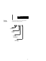
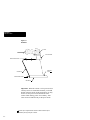
To set up the scanner to operate in Autosense mode
using the optional Autostand follow the steps below
while referring to Figure C.1.
1. Enable the scanner to operate in Autosense mode
by scanning the Enable Autosense (NO) label in
Chapter 5.
2. Attach the Stand Riser to the Stand Base
using two of the supplied #6-32 thumb screws.
3. Attach the Scanner Holder to the top of the Stand
Riser using the other two #6-32 thumb screws.
4. Verify that the reflective label is affixed to the
Stand Base.
5. Place the scanner in the stand as shown in
Figure C.1.
6. Check that the red beam of light is aimed at the
reflective label on the stand.
The Autostand is now ready to read bar code labels
presented to it.
While the scanner is activated in Autosense mode
you are able to remove the scanner from its holder
and use it for hand-held applications. When the
scanner is removed from the Autostand the scanning
beam is turned on automatically to read a bar code
label. If the scanner does not see a label the scanning
beam will turn off after four seconds. Scanning is
re-initiated by manually pulling the trigger. The
scanner can then be placed into the stand once again
and it will function in Autosense mode.
C–1
Appendix C
Autosense Mode
Figure C.1
Autostand
Scanner
Scanner Holder
#6-32 Thumb Screws
Reflective
Label 1
Stand Riser
#6-32 Thumb Screws
Stand Base
Important: When the scanner is to be powered from
a battery such as in a hand-held terminal, you should
disable Autosense mode. In this application, you may
need to use the power conservation mode of the
scanner when drawing power from a battery. Autosense mode will function only in full power mode.
1
C–2
Reflective tape is supplied with the autostand. Additional reflective tape is
available by ordering Catalog No. 2755-NT1.
Appendix
D
A–B
Maintenance
This appendix provides general maintenance
information for your scanner.
Cleaning Window
You may need to clean the window of the scanner.
Carefully clean the window by first removing loose
particles of dirt with clean air. Then use a soft, lint
free cloth moistened with an optical quality cleaning
fluid for plastic lenses and wipe the window in a
single direction (don’t wipe cloth back and forth
across window). Do not leave streaks.
CAUTION:
!
Do not use abrasive material or solvents (e.g., alcohol or acetone) on the
window. These items may damage
the window or finish on the scanner.
WARNING:
!
Inspecting Cables
The scanner has no serviceable parts.
Do not open the housing of the scanner.
Periodically inspect the cable on the scanner for wear
and other signs of damage. A worn or damaged cable
may interfere with the operation of the scanner.
Contact your Allen-Bradley representative to order
replacement cables.
D–1
Appendix
E
A–B
Scanner Parameters
Each bar code label in this manual is preceded by two
characters. The following tables list the two character
mnemonic for each scanner parameter and the page
location of the corresponding label.
Mnemonic
ZA
ZB
ZC
@C
@A
@B
AA
AB
AC
AD
BC
BD
NP
NQ
NO
NN
General Scanner Setup Parameters
Function
Set Scanner to Factory Defaults
Display Scanner Configuration
Transmit Program Version Number
Transmit Program ID
Enable Full Continuous Power
Enable Standby Power
Beeper Off
Beeper On; Volume Low
Beeper On; Volume Medium
Beeper On; Volume Loud
Capture Count=1
Capture Count=2
Disable Spotter Beam
Enable Spotter Beam
Enable Autosense Mode
Disable Autosense Mode
Page #
4-10
5-1
5-2
5-2
5-3
5-3
5-4
5-4
5-4
5-4
5-5
5-5
5-6
5-6
5-7
5-7
E–1
Appendix E
Scanner Commands
Mnemonic
CE
CF
CG
CH
CI
Mnemonic
IA
IB
IC
MA
MB
MC
MD
ME
MF
JA
JB
FA
FB
KA
KB
LA
LB
GA
GB
E–2
Wedge Parameters
Function
Enable Wedge Mode
Terminal Type = PC-AT, PS/2 and 50/60/80,
Allen-Bradley 6121,
Allen-Bradley 1784-T50, -T60
Allen-Bradley 2706-DL40
Allen-Bradley 1784-T35 (AT mode)
Compaq 386, 286
Terminal Type = PC-XT,
Allen-Bradley 6120, 2706-DL40,
Allen-Bradley 1784-T35 (XT mode)
Compaq Deskpro
Terminal Type = IBM 3151, 3472
Terminal Type = DEC VT220, VT240, VT320,
VT340, VT420, VT1000
Message Format Parameters
Function
Prefix = None
Prefix = STX
Prefix = SOH
Suffix=None
Suffix = ETX
Suffix = CR
Suffix = LF
Suffix = HT
Suffix = CR and LF
Disable Scanner Identifier
Enable Scanner Identifier
Disable Code Identifier
Enable Code Identifier
Preamble = None
Preamble = 4 ASCII Characters
Postamble = None
Postamble = 4 ASCII Characters
No Intercharacter Delay
Set Intercharacter Delay
Page #
4-6
4-6
4-6
4-7
4-7
Page #
6-2
6-2
6-2
6-3
6-3
6-3
6-3
6-3
6-3
6-4
6-4
6-5
6-5
6-7
6-7
6-7
6-7
6-10
6-10
Appendix E
Scanner Commands
Mnemonic
OA
OB
OC
OD
OE
OF
OG
OH
OI
QA
QB
QC
QD
QE
QF
QG
QH
QI
QJ
QK
RA
RB
RC
RD
RE
RF
RG
PA
PB
PC
PD
PE
Symbology Parameters
Function
Disable Code 39
Enable Standard Code 39
Enable Full ASCII Code 39
Disable Modulo 43 Check Character
Enable Modulo 43 Check Character
Do Not Transmit Code 39 Start/Stop Characters
Transmit Code 39 Start/Stop Characters
Set Minimum Length for Code 39 Labels
Set Maximum Length for Code 39 Labels
Disable UPC (A and E)
Enable UPC (A and E) with 2 or 5 Digit Supplements
Enable UPC (A and E) without 2 or 5 Digit Supplements
Disable Transmission UPC Number System Digit
Enable Transmission UPC Number System Digit
Disable Transmission UPC Check Digit
Enable Transmission UPC Check Digit
Disable Expanded UPC-E
Enable Expanded UPC-E
Enable UPC to EAN Translation
Disable UPC to EAN Translation
Disable EAN/JAN (8 or 13)
Enable EAN/JAN with 2 or 5 Digit Supplements
Disable EAN/JAN without 2 or 5 Digit Supplements
Disable Transmission EAN/JAN Number System Digit
Enable Transmission EAN/JAN Number System Digit
Disable Transmission EAN/JAN Check Digit
Enable Transmission EAN/JAN Check Digit
Disable Interleaved 2 of 5
Enable Interleaved 2 of 5 without Check Digit
Enable Interleaved 2 of 5 with Check Digit
Set Minimum Length for Interleaved 2 of 5 Labels
Set Maximum Length for Interleaved 2 of 5 Labels
Page #
7-2
7-2
7-2
7-3
7-3
7-3
7-3
7-4
7-4
7-5
7-5
7-5
7-6
7-6
7-6
7-6
7-5
7-5
7-7
7-7
7-8
7-8
7-8
7-9
7-9
7-9
7-9
7-10
7-10
7-10
7-11
7-11
E–3
Appendix E
Scanner Commands
Mnemonic
PF
PG
PH
PI
TA
TB
TC
TD
VA
VB
VC
VD
VE
VF
E–4
Symbology Parameters (continued)
Function
Disable Standard 2 of 5
Enable Standard 2 of 5
Set Minimum Length for Standard 2 of 5 Labels
Set Maximum Length for Standard 2 of 5 Labels
Disable Code 128
Enable Code 128
Set Minimum Length for Code 128 Labels
Set Maximum Length for Code 128 Labels
Disable Codabar
Enable Codabar
Disable Transmission Codabar Start/Stop Characters
Enable Transmission Codabar Start/Stop Characters
Set Minimum Length for Codabar Labels
Set Maximum Length for Codabar Labels
Page #
7-12
7-12
7-12
7-12
7-13
7-13
7-13
7-13
7-14
7-14
7-14
7-14
7-15
7-15
Glossary
A–B
AIM: Acronym for Automatic Identification
Manufacturers.
alphanumeric: The character set containing letters,
numbers, punctuation marks, and symbols.
ASCII: American Standard Code for Information
Interchange. It is a seven-bit code with an optional parity
bit used to represent alphanumerics, punctuation marks,
and control codes.
bar: The dark element of a printed symbol.
bar code: The parallel bars and spaces found in a bar
code symbol.
bar code density: The number of characters which can be
represented in a linear inch.
bar code label: A label that carries a bar code and is
suitable to be affixed to an article.
bar code symbol: A group of parallel bars that represent
a character or group of characters whose spacing is
determined by a specific set of rules. In most cases,
human readable characters are printed below the bars.
bar length: The bar dimension perpendicular to the
bar width.
bar width: The thickness of a bar measured from the
edge closest to the symbol’s start character to the trailing
edge of the same bar.
character: A single group of bars and spaces representing
an individual number, letter or punctuation mark. A
graphic shape representing a letter, number or symbol.
check digit: A digit included within a symbol whose
value is based mathematically on other characters
included in the symbol. It is used to mathematically
check the accuracy of a symbol.
G–1
Glossary
clear area: A clear space, containing no dark marks, that
precedes the start character of a symbol and follows the
stop character.
Codabar: A numeric symbology consisting of 16 data
characters and 4 start/stop characters. Codabar is
primarily used by the medical community.
Code 128: A symbology representing the full 128 ASCII
character set. Numeric data may be represented in a
double density mode where two digits are represented by
one character.
Code 39: An alphanumeric symbology recognized by
most nations, widely used in the manufacturing industry.
code type: See symbology.
decode: The process of translating a bar code into
data characters using a specific set of rules for each
symbology.
decoder: A device used to decode, or make usable, a
digital or analog signal transmitted from a scanning
device. The scanner contains a decoder.
EAN: Acronym for European Article Numbering
system, the international standard bar code for retail
food packages.
element: Dimensionally the narrowest width in a
character, bar or space.
encoded area: The total linear dimension consisting of all
the characters of a code pattern, including start/stop
characters and data.
guard bars: Bars at the ends and center of a UPC and
EAN symbol. They ensure a complete scan of the
bar code.
hex: Abbreviated form of the word hexadecimal. See
hexadecimal.
hexadecimal: A base-16 numbering system that uses the
symbols 0, 1, 2, 3, 4, 5, 6, 7, 8, 9, A, B, C, D, E, F.
G–2
Glossary
horizontal bar code: A bar code or symbol presented in a
manner that its overall length dimension is parallel to the
horizon. The bars look like a picket fence.
Interleaved 2 of 5: A symbology in which characters are
paired together using bars to represent odd number characters and spaces to represent even number characters.
ladder orientation: See vertical bar code.
modulus 43 check character: Used in Code 39 for data
security in addition to the builtin self-checking characters.
The check-character is the modulus 43 sum of all of the
character values in a given message and is the last
character in the code.
orientation: The alignment of bars and spaces to the
scanner. Often referred to as vertical (ladder) or
horizontal (picket fence).
parity bit: An additional non-data bit attached to a binary
word to provide a check of the data integrity by making
the sum of the number of ones in a word always even
or odd.
picket fence code: See horizontal bar code.
scan: The search for a symbol or marks which are to be
optically recognized.
scan area: The area intended to contain a bar code
symbol.
scanner: A device that optically scans bar code symbols
and converts the optical information into digital or analog
form and sends it to a decoder.
self-checking: A bar code or symbol using a checking
algorithm which can be applied to each character to guard
against undetected errors. Codes that are not
self-checking may employ a check digit or other
redundancy in addition to the data message.
space: The lighter element of a bar code formed by the
background between bars.
G–3
Glossary
start/stop characters: Bar code characters that provide
the scanner with information on how the code is bounded
and its orientation. The start character is normally at the
left end of a horizontal code and adjacent to the most
significant character. The stop character is normally at the
end of a horizontal code and adjacent to the least
significant character.
symbology: The conventions, or rules, which govern the
formation of characters and strings in bar codes. The
language of the bar code symbol.
symbol density: The number of characters per
linear inch.
symbol length: The length of the symbol measured from
the beginning of the quiet area adjacent to the start
character to the end of the quiet area adjacent to a stop
character.
UPC: Acronym for Universal Product Code. The
standard bar code for retail food packages in the
United States.
vertical bar code: A code pattern in which the overall
coded area from start to stop is perpendicular to the
horizon. The individual bars appear as rungs of a ladder.
wedge interface: A programmable device with resident
memory capable of translating scanned bar code data so
that it appears that the data was manually entered on a
keyboard.
G–4
Index
A
Accessories, 2–6
Autosense Mode, 2–2
disable, 5–7
enable, 5–7
installing autostand, C–1
Code Identifier, 6–5
Continuous Full Power, 5–3, 8–1
D
Digit Selection Symbols, B–1
B
Bar Code Test Symbols, A–1
E
Beep, 3–7
Beeper Operation, 5–4
C
Cables
scanner interface, 4-2
wedge interface, 2–6, 4-4
EAN/JAN
check digit, 7–9
disable, 7–8
enable with or without
supplements, 7–8
number system digit, 7–9
Enabling Wedge Mode, 4–6
Capture Count, 5–5
Codabar
disable, 7–14
enable, 7–14
maximum length, 7–15
minimum length, 7–15
start/stop characters, 7–14
Code 128
disable, 7–13
enable, 7–13
maximum length, 7–13
minimum length, 7–13
Code 39
enable, 7–2
maximum length, 7–4
minimum length, 7–4
modulo 43 check character, 7–3
start/stop characters, 7–3
F
Factory Default Settings, 4–10
G
General Setup Parameters, 2–3, 5–1
autosense mode, 5–7
beeper operation, 5–4
capture count, 5–5
power consumption, 5–3
spotter beam, 5–6
system status, 5–1
Good Read Indicator, 3–2
I–1
Index
H
Hand-Held Mode, 2–2
I
Message Format Parameters, 2–4,
6–1
code identifier, 6–5
prefix, 6–2
scanner identifier, 6–4
suffix, 6–3
Inspecting Cables, D–1
Interface cable
connecting, 4–2
removing, 4–3
Interleaved 2 of 5
enable with or without
check digit, 7–10
maximum length, 7–11
minimum length, 7–11
O
Operating Modes
autosense mode, 2–2
hand-held mode, 2–2
Operating Ranges, 3–4
Operating Scanner, 3–6
P
K
Keyboard Wedge Interface, 2–1
installing, 4–1
Keyboard Wedge Parameters, 2–3
Parameters, F–1
general setup, 2–3
keyboard wedge, 2–3
message format, 2–4
symbologies, 2–4, 7–1
Postamble, 6–6, 6–7
L
LED Indicators, 3–2
Good Read, 3–2
Scanning, 3–2
Power Consumption
continuous full power, 5–3, 8–1
standby power, 5–3, 8–1
while scanning, 8–1
Power Supply, connecting, 4–5
M
Maintenance
cleaning scanner window, D–1
inspecting cables, D–1
Message Format, 6–1
I–2
Preamble, 6–6, 6–7
Prefix, 6–2
R
Resetting Factory Defaults, 4–12
Index
S
Safety Labels, 3–3
Scanner Identifier, 6–4
Scan Rate, 3–2, 8–1
Scanner
as a keyboard wedge interface, 2–1
beep, 3–7
beeper operation, 5–4
configuration, 4–8
description of, 2–1, 3–1
factory default settings, 4–10
LED Indicators, 3–2
operating ranges, 3–4
operation of, 3–6
power consumption, 5–3
safety labels, 3–3
scan rate, 3–2, 8–1
specifications, 8–1
troubleshooting, 3–8
visible laser diode, 3–1
Scanner Configuration Guidelines,
4–8
Scanning Indicator, 3–2
Scanning Ranges, 3–4
Scanning Tips, 3–7
Selecting Terminal Type, 4–6
Setup
connecting power supply, 4–5
connecting scanner cable, 4–2
connecting wedge cable, 4–4
enabling wedge mode, 4–6
installng wedge interface, 4–1
selecting terminal type, 4–6
terminal powerup sequence, 4–5
Specifications
certification, 8–2
electrical, 8–1
environmental, 8–2
mechanical, 8–2
optical, 8–1
Spotter Beam
disable, 5–6
enable, 5–6
Standard 2 of 5
disable, 7–12
enable, 7–12
maximum length, 7–12
minimum length, 7–12
Standby Power, 5–3, 8–1
Suffix, 6–3
Symbologies, 2–4
Codabar, 7–14
Code 128, 7–13
Code 39, 7–1
EAN/JAN, 7–8
Interleaved 2 of 5, 7–10
label lengths, 7–1
Standard 2 of 5, 7–12
UPC(A and E), 7–5
System Status
current parameter settings, 5–1
program ID, 5–2
version number, 5–2
I–3
Index
T
Transmit Program ID, 5–2
Terminal Types, 2–6, 4–6, 4– 10
Transmit Version Number, 5–2
Troubleshooting, 3–8
U
UPC (A and E)
check digit, 7–6
enable with/without
supplements, 7-5
expanded UPC-E, 7–5
number system character, 7–6
UPC to EAN translation, 7–7
W
Wedge Mode
enabling, 4–6
selecting terminal type, 4–6
I–4
Catalog Number 2755-NU003 Series A
40062-246–01(A)
Copyright 1992 Allen-Bradley Company, Inc.
Printed in USA