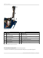
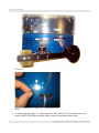
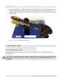
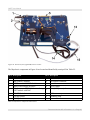
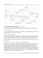
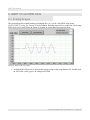
1
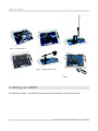
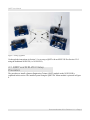
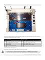
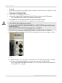
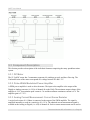
QNET: HVACT, DCMCT, ROTPENT, MECHKIT,
VTOL, and MYOELECTRIC
Quanser Engineering Trainer
for NI-ELVIS
QNET User Manual
Under the copyright laws, this publication may not be reproduced or transmitted in any form,
electronic or mechanical, including photocopying, recording, storing in an information retrieval
system, or translating, in whole or in part, without the prior written consent of Quanser Inc.
Copyright ©2010, by Quanser Inc. All rights reserved.
QNET User Guide
Table of Contents
1. INTRODUCTION..........................................................................................................................................1
2. SETTING UP A QNET...............................................................................................................................2
2.1. QNET and NI ELVIS II Setup Procedure.........................................................................................3
2.2. QNET and ELVIS I Setup Procedure...............................................................................................6
3. QNET-HVACT.....................................................................................................................................8
3.1. General Overview.............................................................................................................................8
3.2. System Schematic...........................................................................................................................10
3.3. Component Description..................................................................................................................11
3.3.1. Halogen Light.......................................................................................................................................11
3.3.2. Fan.......................................................................................................................................................11
3.3.3. Chamber...............................................................................................................................................11
3.3.4. Pulse-Width Modulated Power Amplifier............................................................................................11
3.3.5. Analog Current Measurement: Current Sense Resistor........................................................................12
3.3.6. Analog Voltage Measurement: Voltage Sense.....................................................................................12
3.3.7. Analog Temperature Measurement: Thermistor Sensor.......................................................................12
3.3.8. Fuse......................................................................................................................................................12
3.3.9. QNET Power Supply............................................................................................................................12
3.4. Specifications..................................................................................................................................12
3.5. Environmental.................................................................................................................................13
3.6. Calibration......................................................................................................................................14
4. QNET-DCMCT..................................................................................................................................14
4.1. General Overview...........................................................................................................................14
4.2. System Schematic...........................................................................................................................16
Document Number 850 ♦ Revision 1.11 ♦ Page i
QNET User Guide
4.3. Component Description..................................................................................................................16
4.3.1. DC Motor.............................................................................................................................................17
4.3.2. Pulse-Width Modulated Power Amplifier............................................................................................17
4.3.3. Analog Current Measurement: Current Sense Resistor........................................................................17
4.3.4. Digital Position Measurement: Optical Encoder..................................................................................17
4.3.5. Analog Speed Measurement: Tachometer............................................................................................17
4.3.6. Fuse......................................................................................................................................................17
4.3.7. QNET Power Supply............................................................................................................................17
4.4. Specifications..................................................................................................................................17
4.5. Environmental.................................................................................................................................18
5. QNET-ROTPENT..............................................................................................................................19
5.1. General Overview...........................................................................................................................19
5.2. System Schematic...........................................................................................................................21
5.3. Component Description..................................................................................................................22
5.3.1. DC Motor.............................................................................................................................................22
5.3.2. Pulse-Width Modulated Power Amplifier............................................................................................22
5.3.3. Analog Current Measurement: Current Sense Resistor........................................................................22
5.3.4. Digital Position Measurement: Optical Encoder..................................................................................23
5.3.5. Analog Speed Measurement: Tachometer............................................................................................23
5.3.6. Fuse......................................................................................................................................................23
5.3.7. QNET Power Supply............................................................................................................................23
5.4. Specifications..................................................................................................................................23
5.5. Environmental.................................................................................................................................25
5.6. Assembly........................................................................................................................................25
6. QNET-MECHKIT.............................................................................................................................28
6.1. General Overview...........................................................................................................................28
6.2. System Schematic...........................................................................................................................29
6.3. Component Description..................................................................................................................30
6.3.1. Strain Gage...........................................................................................................................................30
Document Number 850 ♦ Revision 1.11 ♦ Page ii
QNET User Guide
6.3.2. Piezo.....................................................................................................................................................30
6.3.3. Pressure ...............................................................................................................................................30
6.3.4. Thermistor............................................................................................................................................30
6.3.5. Sonar ...................................................................................................................................................31
6.3.6. Infrared.................................................................................................................................................31
6.3.7. Magnetic field .....................................................................................................................................31
6.3.8. Optical Position....................................................................................................................................32
6.3.9. Rotary potentiometer ...........................................................................................................................32
6.3.10. Encoder .............................................................................................................................................32
6.3.11. Micro Switch......................................................................................................................................32
6.3.12. Push Button........................................................................................................................................32
6.3.13. Optical Switch....................................................................................................................................33
6.3.14. Light Emitting Diodes........................................................................................................................33
6.4. Specifications..................................................................................................................................33
7. QNET-VTOL......................................................................................................................................35
7.1. General Overview...........................................................................................................................35
7.2. System Schematic...........................................................................................................................37
7.3. Component Description..................................................................................................................37
7.3.1. Rotor Actuator......................................................................................................................................37
7.3.2. Pulse-Width Modulated Power Amplifier............................................................................................38
7.3.3. Analog Current Measurement: Current Sense Resistor........................................................................38
7.3.4. Analog Voltage Measurement: Voltage Sense.....................................................................................38
7.3.5. Digital Position Measurement: Optical Encoder..................................................................................38
7.3.6. Fuse......................................................................................................................................................38
7.3.7. QNET Power Supply............................................................................................................................39
7.4. Specifications..................................................................................................................................39
7.5. Environmental.................................................................................................................................39
7.6. Assembly........................................................................................................................................40
8. MYOELECTRIC...............................................................................................................................44
8.1. General Overview...........................................................................................................................44
Document Number 850 ♦ Revision 1.11 ♦ Page iii
QNET User Guide
8.2. System Schematic...........................................................................................................................46
8.3. Component Description..................................................................................................................47
8.3.1. Servo Motor.........................................................................................................................................47
8.3.2. Isolation Amplifier...............................................................................................................................47
8.3.3. Muscle Contraction Measurement: EMG Sensor.................................................................................47
8.3.4. DIP Switches........................................................................................................................................48
8.3.5. 555 Timer.............................................................................................................................................48
8.3.6. Fuse......................................................................................................................................................48
8.3.7. QNET Power Supply............................................................................................................................48
8.4. Specifications..................................................................................................................................48
8.5. Environmental.................................................................................................................................49
9. QNET VI LABVIEW HINTS................................................................................................................50
9.1. Scaling Scopes................................................................................................................................50
9.2. Saving Response.............................................................................................................................52
10. TROUBLESHOOTING................................................................................................................................53
10.1. General Software Issues................................................................................................................53
10.2. General Hardware Issues..............................................................................................................54
10.3. HVACT Issues..............................................................................................................................55
10.4. DCMCT Issues.............................................................................................................................56
10.5. ROTPENT Issues..........................................................................................................................56
11. REFERENCES.........................................................................................................................................57
12. CONTACT INFORMATION........................................................................................................................58
Document Number 850 ♦ Revision 1.11 ♦ Page iv
QNET User Manual
1. Introduction
The Quanser Engineering Trainers for NI ELVIS (QNET) modules are listed and briefly described in
Table 1, below, and pictured in figures 1, 2, 3, 4, 5, and 6. These devices work with both the NI ELVIS
I and the NI ELVIS II. Section 2 demonstrates how to setup a QNET with an NI ELVIS. The hardware
of each QNET system is described in sections 3, 4, 5, 6, and 7. Some helpful LabVIEW hints when
using the QNET VIs are given in Section 9 along with a troubleshooting guide in Section 10.
QNET
Name
Full Name
Plant Description
QNET-012
HVACT
Heating-Ventilation
Trainer
Process Control.
QNET-010
DCMCT
DC Motor Control
Trainer
Motion Control.
QNET-011
ROTPENT
Rotary Inverted
Pendulum Trainer
Task-Based Control.
QNET-015
MECHKIT Trainer
Mechatronic Sensors
Trainer
Mechatronics.
QNET-014
VTOL Trainer
Vertical Take-Off and
Landing Trainer
Aerospace.
QNET-016
MYOELECTRIC Trainer Myoelectric Trainer
Biomedical
Table 1: Summary of Quanser Engineering Trainers for NI ELVIS (QNET) devices.
Document Number 850 ♦ Revision 1.11 ♦ Page 1
QNET User Manual
Figure 1: QNET-HVACT
Figure 2: QNET-DCMCT
Figure 3: QNET-ROTPENT
Figure 5: QNET-VTOL Trainer
Figure 4: QNET-MECHKIT Trainer
Figure 6: QNET-MYOELECTRIC
Trainer
2. Setting up a QNET
As illustrated in Figure 7, the QNET boards can easily be connected to an NI ELVIS system.
Document Number 850 ♦ Revision 1.11 ♦ Page 2
QNET User Manual
Figure 7: Setting up QNETs.
Go through the instructions in Section 2.1 to to setup a QNET with an NI ELVIS II or Section 2.2 if
using the traditional NI ELVIS (i.e. NI ELVIS I).
2.1. QNET and NI ELVIS II Setup
Procedure
The procedure to install a Quanser Engineering Trainer (QNET) module on the NI ELVIS II is
explained in this section. The installed system using the QNET DC Motor module is pictured in Figure
8.
Document Number 850 ♦ Revision 1.11 ♦ Page 3
QNET User Manual
Figure 8: Components on ELVIS II and QNET.
Some of the components used in the installation procedure are located and marked by an ID number in
Figure 8 and described in the Table 2, below.
ID #
1
2
3
4
5
Description
NI ELVIS II
Prototyping Board Power Switch
Power LED
Ready LED
Power Cable for ELVIS II
ID #
6
7
8
9
Description
USB Connection between PC and ELVIS II
QNET DC Motor Control Trainer
QNET Power LEDs
QNET Power Cable for QNET
Table 2: ELVIS II and QNET components.
Follow these instructions to setup a QNET board on an ELVIS II:
1. Do NOT make the following connections while power is supplied to the hardware!
2. Place the small opening on the front of the QNET board over the mounting bracket on the NI
Document Number 850 ♦ Revision 1.11 ♦ Page 4
QNET User Manual
3.
4.
5.
6.
7.
8.
ELVIS II.
Slide the PCI connector of the QNET module end into the female connector on the NI ELVIS II.
Make sure it is connected properly.
Connect the ELVIS II power cable.
Connect the ELVIS II USB cable to the PC.
Connect the supplied QNET transformer to the QNET power jack on the QNET module.
Note: Not required for the QNET mechatronic sensors trainer.
Power the NI ELVIS II by turning ON the System Switch on the rear panel.
Turn ON the Prototyping Board Power switch, ID #2 shown in Figure 8.
9. Turn OFF the Prototyping Board switch if
(1) On the QNET-DCMCT, QNET-ROTPENT, or QNET-VTOL Trainer the DC motor
begins to turn, or
(2) On the QNET-HVACT the halogen light turns on brightly.
Take extra care when powering the QNET module to avoid causing any damage!
10. The Power and Ready LEDs of the NI ELVIS II unit should be lit as shown in Figure 9, below.
Figure 9: Ready and Power LEDs on NI
ELVIS II.
11. As pictured in Figure 10, verify that the +15V,-15V, +5V, and +B LEDs on the QNET module
are lit. They indicate that the board has been properly connected to the ELVIS unit.
Note: For the QNET-MECHKIT, ensure the +15V,-15V, and +5V LEDs are lit (it does not
require QNET power supply).
Document Number 850 ♦ Revision 1.11 ♦ Page 5
QNET User Manual
Figure 10: QNET LEDs should all be
on.
2.2. QNET and ELVIS I Setup
Procedure
The procedure to setup a QNET on the NI ELVIS I is explained in this section. The installed system
using the QNET DC Motor module is pictured in Figure 11.
Document Number 850 ♦ Revision 1.11 ♦ Page 6
QNET User Manual
Figure 11: NI ELVIS and QNET-DCMCT setup for use with LabVIEW.
Some of the components used in the installation procedure are located and marked by an ID number in
Figure 11 and described in the Table 3, below.
ID # Description
NI ELVIS Benchtop Workstation
1
(Traditional NI ELVIS or NI ELVIS I)
2
Prototyping Board Power Switch
3
Communications Switch
4
Power Cable of NI ELVIS I
ID # Description
5
68-Pin E-Series or M-Series DACB Cable
6
7
QNET DC Motor Control Trainer
QNET Power Cable
Table 3: ELVIS I and QNET components.
Follow these instructions to setup a QNET board on an ELVIS I:
1. Do NOT make the following connections while power is supplied to the hardware!
2. Place the small opening on the front of the QNET board over the mounting bracket on the NI
Document Number 850 ♦ Revision 1.11 ♦ Page 7
QNET User Manual
3.
4.
5.
6.
7.
8.
ELVIS (note that some ELVIS workstations may not have mounting brackets).
Slide the PCI connector of the QNET module end into the female connector on the NI ELVIS II.
Make sure it is connected properly.
Connect the NI ELVIS power cable shown as ID #4 in Figure 11.
Connect the QNET power cable labeled ID #7 in Figure 11.
Note: Not required for the QNET mechatronic sensors trainer.
Ensure the Prototyping Board Power switch, ID #2, is set to the OFF position and the
Communications switch, ID #3, is set to the BYPASS mode.
Power the NI ELVIS Benchtop Workstation by turning the Standby Switch on the rear panel of
the system to ON.
Turn ON the Prototyping Board Power switch.
9. Turn OFF the Prototyping Board switch if
(1) On the QNET-DCMCT, QNET-ROTPENT, or QNET-VTOL Trainer the DC motor
begins to turn, or
(2) On the QNET-HVACT the halogen light turns on brightly.
Take extra care when powering the QNET module to avoid causing any damage!
10. The System Power, Prototyping Board, and Communications LEDs situated on the front panel
of the NI ELVIS unit should all be lit.
11. Verify that the +15V, -15V, +5V, and +B LEDs on the QNET module are lit. They indicate that
the board has been properly connected to the ELVIS unit.
Note: For the QNET-MECHKIT, ensure the +15V,-15V, and +5V LEDs are lit (it does not
require QNET power supply).
3. QNET-HVACT
3.1. General Overview
The photograph in Figure 12 shows an overview and the general layout of the QNET heating and
ventilation trainer (HVAC trainer) system.
CAUTION: Ensure the HVAC trainer is setup as dictated in Section 2 and used as described in
the Reference [1]. The HVAC trainer is susceptible to protection impairment if not used as
specified.
Document Number 850 ♦ Revision 1.11 ♦ Page 8
QNET User Manual
Figure 12: General layout of QNET-HVACT.
The HVACT components in Figure 12 and Figure 13 are located and identified by a unique ID in Table
Table 4.
Figure 13: Components of QNET-HVACT heating chamber.
Document Number 850 ♦ Revision 1.11 ♦ Page 9
QNET User Manual
ID #
Description
ID # Description
1
Halogen light bulb (i.e. heater)
8
Chamber thermistor gain
2
Fan (i.e. cooling)
9
Chamber thermistor offset
3
Thermistor chamber temperature sensor
10
Ambient thermistor offset
4
Chamber
11
Ambient thermistor gain
5
Thermistor ambient temperature sensor
12
24V QNET power jack
6
PCI connector to NI ELVIS: for
interfacing QNET module with DAC.
13
Fuse
7
QNET PWM/Encoder board
14
+B, +15V, -15V, +5V LEDs
Table 4: HVACT Component Nomenclature
3.2. System Schematic
A schematic of the HVACT system interfaced with a DAQ device is provided in Figure 14.
Document Number 850 ♦ Revision 1.11 ♦ Page 10
QNET User Manual
Figure 14: Schematic of QNET-HVACT system.
3.3. Component Description
This Section provides a description of the individual elements comprising the full HVACT system.
3.3.1. Halogen Light
The halogen light is rated at 12-Volts.
3.3.2. Fan
The blower is a 24-Volt variable-speed fan. There is a constant voltage of 16-Volts applied to the fan.
3.3.3. Chamber
The chamber, or duct, is constructed from Plexiglas.
3.3.4. Pulse-Width Modulated Power Amplifier
A PWM power amplifier is used to drive the halogen bulb to heat the chamber. The input to the
Document Number 850 ♦ Revision 1.11 ♦ Page 11
QNET User Manual
amplifier is the output of the Digital-to-Analog converter (i.e. D/A) of channel #0 on the DAQ. The
maximum output voltage of the amplifier is 24 V. Its maximum peak current is 5 A and the maximum
continuous current is 4 A. The amplifier gain is 2.3 V/V.
3.3.5. Analog Current Measurement: Current Sense Resistor
A series load resistor of 0.1 Ohms is connected to the output of the PWM amplifier. The signal is
amplified internally to result in a sensitivity of 1.0 V/A. The obtained current measurement signal is
available at the Analog-to-Digital (i.e. A/D) of channel #0. Such a current measurement can be used to
monitor the current in the heater.
3.3.6. Analog Voltage Measurement: Voltage Sense
The analog signal proportional to the voltage output of the PWM amplifier is available at the Analogto-Digital (i.e. A/D) channel #2 of the DACB. The voltage sensor sensitivity is 3.33 V/V. Such a
voltage measurement can be used to monitor the voltage applied to the heater.
3.3.7. Analog Temperature Measurement: Thermistor Sensor
An analog voltage signal proportional to the temperature is available at the Analog-to-Digital (i.e. A/D)
Input channels #5 and #7 of the DAQ. The AI #5 channel gives the chamber temperature signal and the
AI #7 channel reads the ambient temperature signal. The sensitivity of the thermistor sensor is 20.0
oC/V.
3.3.8. Fuse
The QNET power amplifier has a 250 V, 3 A fuse.
3.3.9. QNET Power Supply
The HVACT has a 24-Volt DC power jack to power the on-board PWM amplifier. It is called the
QNET power supply. The +B LED on the QNET board turns bright green when the amplifier is
powered.
CAUTION: Please make sure you use the correct type of wall transformer or you will damage the
system. It should supply 24 VDC and be rated at 3.0 A.
3.4. Specifications
The specifications of the HVACT system model parameters are given in Table 5.
Document Number 850 ♦ Revision 1.11 ♦ Page 12
QNET User Manual
Symbol
Description
Value
Unit
0.01
°C/(V.s)
PWM amplifier maximum output voltage
24
V
PWM amplifier maximum output current
5
A
PWM amplifier gain
2.3
V/V
Halogen Light:
Kv
Heater ramp gain.
Pulse-Width Modulated Amplifier:
Vmax
Table 5: HVACT model parameter and PWM power amplifier specifications.
The specifications on the HVACT system sensors are given in Table 6.
Description
Value
Unit
Current calibration
1
A/V
Current sense resistor
0.1
ohms
3.33
V/V
20
°C/V
Current Sense:
Voltage Sense:
Voltage calibration.
Thermistor:
Thermistor calibration at QNET A/D input
Table 6: HVACT sensor parameter specifications.
3.5. Environmental
The HVACT environmental operating conditions are given in Table 7.
Description
Value
Unit
Operating temperature
15 to 35
°C
Humidity
20 to 90
%
Table 7: QNET HVACT environmental operating conditions.
CAUTION: Ensure the unit is operated under the temperature and humidity conditions given in
Table 7. Otherwise, there may be some issues with the motion control experiment results.
Document Number 850 ♦ Revision 1.11 ♦ Page 13
QNET User Manual
3.6. Calibration
Follow this procedure to calibrate the thermistor sensors that measure the chamber and ambient
temperature on the QNET-HVACT module:
1. Power the NI ELVIS and the QNET as described in Section 2.
2. Open and run the LabVIEW virtual instrument QNET_HVACT_On_Off_Control as described
in the Reference [1].
3. Let the fan cool down the chamber for at least 2 minutes and make sure the heater if OFF!
In the Digital Scopes section of the VI, make sure the Chamber Temp and the Ambient Temp are
reading values suitable for the control laboratory. See the Troubleshooting Section on Page 53
for more information.
4. If the sensors definitely need to be re-calibrated, remove the plastic cover on the QNETHVACT module by loosening its four screws.
5. The thermistor offset can be changed on the QNET PWM/Encoder board. The offset of the
chamber thermistor and ambient thermistor sensors are ID #9 and ID #10 in Figure 12. Take a
screwdriver with a small head and vary the knob corresponding to the sensor that needs to be
calibrated. The offset is decreased by turning the knob clockwise.
6. While the knob is turned, examine the change in temperature in the Digital Scopes section of
the VI. Adjust it until the chamber and/or ambient temperature read acceptable values.
7. Do not change the sensor gain adjustments, ID #8 and ID #11 in Figure 12. They are both
turned counter-clockwise to get the maximum gain before the shipment.
4. QNET-DCMCT
4.1. General Overview
The photograph in Figure 15 shows an overview and the general layout of the QNET DC Motor
Control Trainer (DCMCT) system.
CAUTION: Ensure the DCMCT is setup as dictated in Section 2 and used as described in the
Reference [1]. The DCMCT is susceptible to protection impairment if not used as specified.
Document Number 850 ♦ Revision 1.11 ♦ Page 14
QNET User Manual
Figure 15: General layout of QNET DCMCT.
The DCMCT components in Figure 15and Figure 16 are located and identified by a unique ID in Table
8.
Figure 16: QNET DC motor components.
Document Number 850 ♦ Revision 1.11 ♦ Page 15
QNET User Manual
ID #
1
2
3
4
5
Description
DC motor
High-resolution encoder
Motor metal chamber
Inertial load
PCI connector to NI ELVIS: for interfacing
QNET module with DAC
ID #
6
7
8
9
Description
QNET PWM/Encoder board
24V QNET power jack
Fuse
+B, +15V, -15V, +5V LEDs
Table 8: DCMCT component nomenclature.
4.2. System Schematic
A schematic of the DCMCT system interfaced with a DAQ device is provided in Figure 17.
Figure 17: Schematic of QNET-DCMCT system.
4.3. Component Description
This section provides a description of the individual elements comprising the full DCMCT system.
Document Number 850 ♦ Revision 1.11 ♦ Page 16
QNET User Manual
4.3.1. DC Motor
The 12-Volt DC motor has 5 commutator segments, 64 windings per pole, and has a flux ring. The
Coulomb friction of the motor corresponds to a voltage between 0.5 and 1.5 V.
4.3.2. Pulse-Width Modulated Power Amplifier
A PWM power amplifier is used to drive the motor. The input to the amplifier is the output of the
Digital-to-Analog converter (i.e. D/A) of channel #0 on the DAQ. The maximum output voltage of the
amplifier is 24 V. Its maximum peak current is 5 A and the maximum continuous current is 4 A. The
amplifier gain is 2.3 V/V.
4.3.3. Analog Current Measurement: Current Sense Resistor
A series load resistor of 0.1 Ohms is connected to the output of the PWM amplifier. The signal is
amplified internally to result in a sensitivity of 1.0 V/A. The obtained current measurement signal is
available at the Analog-to-Digital (i.e. A/D) of channel #0. Such a current measurement can be used to
monitor the current running in the motor.
4.3.4. Digital Position Measurement: Optical Encoder
Digital position measurement is obtained by using a high-resolution quadrature optical encoder. This
optical encoder is directly mounted to the rear of the motor. The encoder count measurement is
available at Digital Input (i.e. DI) channel #0 of the DAQ.
4.3.5. Analog Speed Measurement: Tachometer
An analog signal proportional to motor speed is available at the Analog-to-Digital (i.e. A/D) Input
channel #4 on the DAQ. It is digitally derived from the encoder signal on the QNET DCMCT board.
4.3.6. Fuse
The QNET power amplifier has a 250 V, 3 A fuse.
4.3.7. QNET Power Supply
The DCMCT module has a 24-Volt DC power jack to power the on-board PWM amplifier. It is called
the QNET power supply. The +B LED on the QNET board turns bright green when the amplifier is
powered.
CAUTION: Please make sure you use the correct type of wall transformer or you will damage the
system. It should supply 24 VDC and be rated at 3.0 A.
4.4. Specifications
The specifications of the DCMCT system model parameters are given in Table 9.
Document Number 850 ♦ Revision 1.11 ♦ Page 17
QNET User Manual
Symbol
Description
Motor:
Value
Unit
Rm
Motor armature resistance.
8.7
Ohm
Kt
Motor torque constant.
0.03334
N.m
Km
Motor back-emf constant (same as Kt in SI units).
0.03334
V/(rad/s)
Jm
Moment of inertia of motor rotor
Maximum continuous torque
Maximum power rating
Maximum continuous current
1.80E-006 kg.m2
0.10
N.m
20.0
W
1.0
A
Ml
Inertial load disc mass
0.033
kg
rl
Inertial load disc radius
0.0242
m
PWM amplifier maximum output voltage
24
V
PWM amplifier maximum output current
PWM amplifier gain
5
2.3
A
V/V
Pulse-Width Modulated Amplifier:
Vmax
Table 9: DCMCT model parameter and PWM power amplifier specifications.
The specifications on the DCMCT system sensors are given in Table 10.
Description
Current Sense:
Current calibration
Current sense resistor
Encoder:
Encoder line count
Encoder resolution (in quadrature mode)
Encoder type
Encoder signals
Tachometer:
Tachometer calibration at QNET A/D input
Value
Unit
1.0
0.1
A/V
ohms
360
0.25
TTL
A,B
lines/rev
deg/count
2987
RPM/V
Table 10: DCMCT sensor parameter specifications.
4.5. Environmental
The DC motor control trainer environmental operating conditions are given in Table 11.
Document Number 850 ♦ Revision 1.11 ♦ Page 18
QNET User Manual
Description
Value
Unit
Operating temperature
15 to 35
°C
Humidity
20 to 90
%
Table 11: QNET DC motor control trainer environmental operating conditions.
CAUTION: Ensure the unit is operated under the temperature and humidity conditions given in
Table 11. Otherwise, there may be some issues with the heating and cooling results.
5. QNET-ROTPENT
5.1. General Overview
The photograph in Figure 18 shows an overview and the general layout of the QNET Rotary Pendulum
Control Trainer (ROTPENT) device.
CAUTION: Ensure the ROTPENT is setup as dictated in Section 2 and used as described in the
Reference [1]. The ROTPENT is susceptible to protection impairment if not used as specified.
Document Number 850 ♦ Revision 1.11 ♦ Page 19
QNET User Manual
Figure 18: General layout of QNET ROTPENT.
The ROTPENT components in Figure 18 and Figure 19 are located and identified by a unique ID in
Table 12.
Document Number 850 ♦ Revision 1.11 ♦ Page 20
QNET User Manual
Figure 19: Components of QNET-ROTPENT
pendulum assembly.
ID # Description
1
DC motor
High-resolution encoder that
2
measured arm angle
ID # Description
8
Pendulum link
3
Motor metal chamber
10
4
5
6
7
Rotary arm pivot
Rotary arm
Pendulum encoder
Pendulum pivot
11
12
13
14
9
Pendulum weight
PCI connector to NI ELVIS: for interfacing QNET
module with DAC.
QNET PWM/Encoder board
24V QNET power jack
Fuse
+B, +15V, -15V, +5V LEDs
Table 12: ROTPENT component nomenclature.
5.2. System Schematic
A schematic of the ROTPENT system interfaced with a DAQ device is provided in Figure 20.
Document Number 850 ♦ Revision 1.11 ♦ Page 21
QNET User Manual
Figure 20: Schematic of QNET-ROTPEN system.
5.3. Component Description
This Section provides a description of the individual elements comprising the rotary pendulum trainer
system.
5.3.1. DC Motor
The 12-Volt DC motor has 5 commutator segments, 64 windings per pole, and has a flux ring. The
Coulomb friction of the motor corresponds to a voltage between 0.5 and 1.5 V.
5.3.2. Pulse-Width Modulated Power Amplifier
A PWM power amplifier is used to drive the motor. The input to the amplifier is the output of the
Digital-to-Analog converter (i.e. D/A) of channel #0 on the DAQ. The maximum output voltage of the
amplifier is 24 V. Its maximum peak current is 5 A and the maximum continuous current is 4 A. The
amplifier gain is 2.3 V/V.
5.3.3. Analog Current Measurement: Current Sense Resistor
A series load resistor of 0.1 Ohms is connected to the output of the PWM amplifier. The signal is
amplified internally to result in a sensitivity of 1.0 V/A. The obtained current measurement signal is
available at the Analog-to-Digital (i.e. A/D) of channel #0. Such a current measurement can be used to
Document Number 850 ♦ Revision 1.11 ♦ Page 22
QNET User Manual
monitor the current running in the motor.
5.3.4. Digital Position Measurement: Optical Encoder
Digital position measurement is obtained by using a high-resolution quadrature optical encoder. There
is one optical encoder directly mounted to the rear of the motor and another that measured the
pendulum pivot angle. The motor encoder count measurement is available at Digital Input (i.e. DI)
channel #0 on the DAQB and the pendulum encoder count is available at DI#1 on the DAQB .
5.3.5. Analog Speed Measurement: Tachometer
An analog signal proportional to motor speed is available at the Analog-to-Digital (i.e. A/D) Input
channel #4 of the DAQ. It is digitally derived from the encoder signal on the QNET board.
5.3.6. Fuse
The QNET power amplifier has a 250 V, 3 A fuse.
5.3.7. QNET Power Supply
The ROTPENT module has a 24-Volt DC power jack to power the on-board PWM amplifier. It is
called the QNET power supply. The +B LED on the QNET board turns bright green when the amplifier
is powered.
CAUTION: Please make sure you use the correct type of wall transformer or you will damage the
system. It should supply 24 VDC and be rated at 3.0 A.
5.4. Specifications
The specifications of the ROTPENT system model parameters are given in Table 13.
Symbol
Description
Motor:
Value
Unit
Rm
Motor armature resistance.
8.7
ohms
Kt
Motor torque constant.
0.03334
N.m
Km
Motor back-emf constant (same as Kt in SI units).
0.03334
V/(rad/s)
Jm
Moment of inertia of motor rotor.
1.80E-006 kg.m2
Jeq
Equivalent moment of inertia about motor shaft pivot axis with
pendulum assembly.
Motor maximum continuous torque
Motor maximum power rating
Motor maximum continuous current
1.84E-004 kg.m2
0.10
20.0
1.0
N.m
W
A
Document Number 850 ♦ Revision 1.11 ♦ Page 23
QNET User Manual
Pendulum Arm:
Marm
Mass of the arm.
0.08
kg
r
Beq
Length of arm pivot to pendulum pivot.
0.0826
m
Arm viscous damping.
0.000
N.m/(rad/s)
Pendulum Link:
Mp
Mass of the pendulum link and weight combined.
0.0270
kg
Lp
Total length of pendulum.
0.191
m
lp
Length of pendulum center of mass from pivot.
0.153
m
Mp1
Mass of the pendulum link.
0.008
kg
Mp2
Mass of the pendulum weight.
0.019
kg
Lp1
Length of pendulum link.
0.171
m
Lp2
Length of pendulum weight.
0.190
m
Jp
Pendulum moment of inertia about its pivot axis.
1.70E-04
kg.m2
Bp
Pendulum viscous damping.
0.000
N.m/(rad/s)
PWM amplifier maximum output voltage
24
V
PWM amplifier maximum output current
PWM amplifier gain
5
2.3
A
V/V
Pulse-Width Modulated Amplifier:
Vmax
Table 13: ROTPENT model parameter and PWM power amplifier specifications.
The viscous damping parameters of the pendulum, Bp, and of the arm, Beq, are regarded as being
negligible in this laboratory.
The specifications on the ROTPENT system sensors are given in Table 14.
Document Number 850 ♦ Revision 1.11 ♦ Page 24
QNET User Manual
Description
Current Sense:
Current calibration
Current sense resistor
Pendulum Encoder:
Encoder line count
Encoder resolution (in quadrature mode)
Encoder type
Encoder signals
Motor Encoder:
Encoder line count
Encoder resolution (in quadrature mode)
Encoder type
Encoder signals
Tachometer:
Tachometer calibration at QNET A/D input
Value
Unit
1.0
0.1
A/V
ohms
1024
0.0879
TTL
A,B
lines/rev
deg/count
360
0.25
TTL
A,B
lines/rev
deg/count
2987
RPM/V
Table 14: ROTPENT sensor parameter specifications.
5.5. Environmental
The QNET rotary pendulum control trainer environmental operating conditions are given in Table 15.
Description
Value
Unit
Operating temperature
15 to 35
°C
Humidity
20 to 90
%
Table 15: QNET rotary pendulum trainer environmental operating conditions.
CAUTION: Ensure the unit is operated under the temperature and humidity conditions given in
Table 15. Otherwise, there may be some issues with the running the experiments.
5.6. Assembly
Follow the instructions below to setup the QNET Rotary Pendulum trainer for experimental use.
1. The ROTPENT device comes disassembled as pictured in Figure 21, below.
Document Number 850 ♦ Revision 1.11 ♦ Page 25
QNET User Manual
Figure 21: Disassembled QNET-ROTPENT.
2. Remove the thumbscrews from the bottom of the DC motor chamber.
3. Align the four screw holes on the bottom of the chassis with four holes on the QNET base. The
ROTPEN should be upright similarly as shown in Figure 22.
Document Number 850 ♦ Revision 1.11 ♦ Page 26
QNET User Manual
Figure 22: Place the QNET-ROTPENT upright on
the module and align screw holes.
4. Tighten the four thumbscrews from the bottom of the QNET module board though the DC
motor chamber. This is pictured below in Figure 23.
Figure 23: Tighten four thumbscrews.
Document Number 850 ♦ Revision 1.11 ♦ Page 27
QNET User Manual
5. The final system should look similarly as shown in Figure 18, above.
6. QNET-MECHKIT
6.1. General Overview
The photograph in Figure 24 shows an overview and the general layout of the QNET mechatronic
sensors trainer (MECHKIT) system.
CAUTION: Ensure the MECHKIT trainer is setup as dictated in Section 2 and used as described
in the Reference [1]. The MECHKIT trainer is susceptible to protection impairment if not used
as specified.
Figure 24: General layout of QNET mechatronics sensors trainer.
The MECHKIT components in Figure 24, above, are located and identified by a unique ID in Table 16.
Document Number 850 ♦ Revision 1.11 ♦ Page 28
QNET User Manual
ID #
Description
ID # Description
1
Piezo Sensor
16
Enc B LED
2
Flexible link (connected to strain gage)
17
Enc Index LED
3
Flexible link ruler
18
Optical position sensor knob
4
Temperature sensor gain potentiometer
19
Magnetic field sensor knob
5
Temperature sensor offset potentiometer
20
AD0 Jumper
6
Thermistor
21
AD1 Jumper
7
Push button
22
AD2 Jumper
8
Micro switch
23
AD5 Jumper
9
Optical switch
24
Potentiometer
10
Infrared sensor on/off switch
25
DO 1 LED
11
Infrared sensor on/off LED
26
DO 0 LED
12
Infrared sensor
27
Plunger (connected to pressure sensor)
13
Sonar sensor
28
Pressure sensor
14
Encoder knob
29
Plunger ruler
15
Enc A LED
30
PCI connector to NI ELVIS: for interfacing
QNET module with DAC.
Table 16: MECHKIT component nomenclature.
6.2. System Schematic
A schematic of the MECHKIT system interfaced with a DAQ device is provided in Figure 25.
Document Number 850 ♦ Revision 1.11 ♦ Page 29
QNET User Manual
Figure 25: Schematic of QNET-MECHKIT system.
Remark: The Digital Output channels for the LEDs are different on the ELVIS I. On the ELVIS I, LED
8 is connected to DO #8 and LED 7 is connected to DO #9.
6.3. Component Description
6.3.1. Strain Gage
The strain gage is mounted on the flexible link and outputs a voltage ranging between +/- 5.0 V relative
to the amount of deflection.
6.3.2. Piezo
The piezo is a flexible component that includes a piezoelectric polymer film that is laminated to a
polyester substrate. The laminated strip contains an added mass at the end weighing 0.78 g. See Table
17 for sensitivity and resonance specifications.
6.3.3. Pressure
As outlined in Table 17, the pressure transducer on the QNET mechatronic sensors trainer has a range
of 0-30 PSI, a sensitivity of 0.133 V/PSI, and outputs a voltage between 0.5-4.5 V. Thus it has a zero
pressure offset of 0.5 V and a full-scale span of 4.5 V.
6.3.4. Thermistor
The thermistor is the in the circuit shown in Figure 26 and is the component labeled by R. The Gain
and Offset components represent the potentiometer knobs on the QNET mechatronic sensors trainer.
The Offset changes the offset of the input offset voltage, vi, and the Gain changes the value of the
amplifier gain, Av.
Document Number 850 ♦ Revision 1.11 ♦ Page 30
QNET User Manual
Figure 26: Thermistor circuit on QNET mechatronic sensors trainer.
6.3.5. Sonar
The sonar range finder device on the QNET MECHKIT has a operating measuring range of 6-254
inches and a resolution of 1-inch. It can detect objects in the range of 0-254 inches. The sonar sensor
specifications are listed in Table 17.
6.3.6. Infrared
The infrared distance measuring unit uses a triangulation method to detect the distance of an object and
has a distance measuring range of 20-150 cm, as given in Table 17. It outputs a voltage that correlates
to the distance of the target.
6.3.7. Magnetic field
The linear magnetic field transducer on the QNET mechatronic sensors trainer outputs a voltage that is
proportional to the magnetic field that is applied perpendicularly to the object being measured. The
relationship, however, between the output voltage and the target distance is exponential.
Document Number 850 ♦ Revision 1.11 ♦ Page 31
QNET User Manual
6.3.8. Optical Position
The optical position sensor on the QNET MECHKIT board consists of an infrared emitting diode and a
silicon photo-transistor, both mounted side by side. The range of the optical position sensor on the
QNET MECHKIT is 0.25 inches, as given in Table 17.
6.3.9. Rotary potentiometer
The rotary potentiometer outputs a voltage that varies linearly with the angle being measured. As listed
in Table 17, the potentiometer has a mechanical limit of 300 degrees.
6.3.10. Encoder
The encoder knob is fitted onto a spindle with 9 teeth. As spindle is rotates, the teeth go through two
optical switches and generate the encoder A and B signals. The index pulse is generated by a magnetic
pickup sensor.
6.3.11. Micro Switch
The analog input line connected to the miniature snap action switch is pulled high, to +5V, when the
switch is in open position and goes down to low when pressed down. The micro switch circuit is
depicted in Figure 27.
Figure 27: Micro switch circuit.
6.3.12. Push Button
The push button analog line goes to +5V when the button is pressed down, i.e. when the switch is
Document Number 850 ♦ Revision 1.11 ♦ Page 32
QNET User Manual
closed. Its circuit is shown in Figure 28, below.
Figure 28: Push button circuit.
6.3.13. Optical Switch
The optical switch is a photo-microsensor that consists of a transmissive and a reflective component. If
an object is placed between the components and the reflective sensor does not sense any light, the
output goes high to +5V. The switch outputs 0V when no object is detected.
6.3.14. Light Emitting Diodes
The yellow light emitting diode, LED 7, is connected to Digital Output #9 on the ELVIS II and DO#1
on ELVIS I. The red LED, LED 8, is connected to Digital Output #8 on the ELVIS II and DO#0 on
ELVIS I. The yellow LED is active high whereas the red LED is active low.
6.4. Specifications
Some of the sensor specifications for the MECHKIT are given in Table 17.
Document Number 850 ♦ Revision 1.11 ♦ Page 33
QNET User Manual
Description
Value
Unit
Mechanical angle range
300.000
deg
Independent linearity
+/-5
%
20 to 150
cm
Pressure range
0-30
PSI
Sensitivity
0.133
V/PSI
Output range
0.5-4.5
V
Quantization step
3.0
mV
Accuracy
+/-2
%Vs
Object detection
0-254
in
Sonar range
6-254
in
Resolution
1.0
in
Reading frequency
20.0
Hz
Ring mass on film
0.72
g
Location of mass from edge
1.40
cm
Sensitivity at resonance
16.0
V/g
Resonant frequency
40.0
Hz
3 dB frequency
20.0
Hz
0.25
in
Potentiometer
Infrared Sensor
Distance measuring range
Pressure Sensor
Sonar
Piezo Film
For 0.78 g added mass:
Optical Position
Range
Table 17: MECHKIT Specifications
Document Number 850 ♦ Revision 1.11 ♦ Page 34
QNET User Manual
7. QNET-VTOL
7.1. General Overview
The pictures in Figure 29 and Figure 30 show the general layout of the QNET vertical take-off and
landing trainer.
CAUTION: Ensure the VTOL trainer is setup as dictated in Section 2 and used as described in
the Reference [1]. The VTOL trainer is susceptible to protection impairment if not used as
specified.
Figure 29: Front view of VTOL layout.
Document Number 850 ♦ Revision 1.11 ♦ Page 35
QNET User Manual
Figure 30: Top view of VTOL layout.
The VTOL components in Figure 29 and Figure 30 are located and identified by unique ID in Table 18.
ID #
Description
ID # Description
1
DC Motor
9
Encoder
2
Motor leads (connects amplifier to motor)
10
Counterweight
3
Propeller holder
11
Counterweight thumbscrews
4
Propeller shield
12
PCI connector to NI ELVIS: for interfacing
QNET module with DAC.
5
VTOL body
13
QNET PWM/Encoder board
6
Pivot / encoder shaft
14
24V QNET power jack
7
Support arm
15
Fuse
8
Support thumbscrews
16
+B, +15V, -15V, +5V LEDs
Table 18: VTOL component nomenclature.
Document Number 850 ♦ Revision 1.11 ♦ Page 36
QNET User Manual
7.2. System Schematic
A schematic of the VTOL system interfaced with a DAQ device is provided in Figure 31.
Figure 31: Schematic of QNET-VTOL system.
7.3. Component Description
7.3.1. Rotor Actuator
The EM150 DC motor and the EP2245X6 rotor have the specifications given in Table 19.
Document Number 850 ♦ Revision 1.11 ♦ Page 37
QNET User Manual
Volts (V)
Amps (A)
Thrust (g)
Thrust (oz)
Power (W)
Efficiency
(g/W)
Efficiency
(oz/kW)
3.6
1.5
32
1.13
5.4
5.93
209
4.8
2.2
50
1.76
10.56
4.73
167
6
3
77
2.72
18
4.28
151
7.2
3.8
95
3.35
27.36
3.47
122
8.4
4.8
119
4.2
40.32
2.95
104
9.6
5.9
141
4.97
56.64
2.49
88
10.8
6.6
152
5.36
71.28
2.13
75
Table 19: VTOL rotor specifications.
7.3.2. Pulse-Width Modulated Power Amplifier
A PWM power amplifier is used to drive the VTOL DC motor. The input to the amplifier is the output
of the Digital-to-Analog converter (i.e. D/A) of channel #0 on the DAQ. The maximum output voltage
of the amplifier is 24 V. Its maximum peak current is 5 A and the maximum continuous current is 4 A.
The amplifier gain is 2.3 V/V.
7.3.3. Analog Current Measurement: Current Sense Resistor
A series load resistor of 0.1 Ohms is connected to the output of the PWM amplifier. The signal is
amplified internally to result in a sensitivity of 1.0 V/A. The obtained current measurement signal is
available at the Analog-to-Digital (i.e. A/D) of channel #0. Such a current measurement can be used to
monitor the current in the heater.
7.3.4. Analog Voltage Measurement: Voltage Sense
The analog signal proportional to the voltage output of the PWM amplifier is available at the Analogto-Digital (i.e. A/D) channel #4 of the DACB. The voltage sensor sensitivity is 3.33 V/V. Such a
voltage measurement can be used to monitor the voltage applied to the heater.
7.3.5. Digital Position Measurement: Optical Encoder
Digital position measurement is obtained by using a high-resolution quadrature optical encoder. This
optical encoder is mounted near the top of the VTOL support arm. The encoder shaft is used as the
pivot of the VTOL body. The encoder count measurement is available at Digital Input (i.e. DI) channel
#0 of the DAQ.
7.3.6. Fuse
The QNET power amplifier has a 250 V, 3 A fuse.
Document Number 850 ♦ Revision 1.11 ♦ Page 38
QNET User Manual
7.3.7. QNET Power Supply
The VTOL module has a 24-Volt DC power jack to power the on-board PWM amplifier. It is called the
QNET power supply. The +B LED on the QNET board turns bright green when the amplifier is
powered.
CAUTION: Please make sure you use the correct type of wall transformer or you will damage the
system. It should supply 24 VDC and be rated at 3.0 A.
7.4. Specifications
The VTOL specifications listed in Table 20 include the various masses and lengths of the system as
well as the viscous damping. Note that the viscous damping is estimated and will vary between
different VTOL units.
Description
Symbol
Value
Unit
Propeller mass
m1
0.068
kg
Counter-weight mass
m2
0.27
kg
VTOL body mass
mh
0.048
kg
Length from pivot to propeller center
l1
15.6
cm
Length from pivot to center of counter-weight l2
5.6
cm
Total length of helicopter body.
Lh
28.4
cm
Estimated viscous damping of VTOL (this
may vary from unit to unit).
B
0.002
N.m/(rad/s)
Table 20: VTOL Specifications
7.5. Environmental
The QNET VTOL environmental operating conditions are given in Table 21.
Description
Value
Unit
Operating temperature
15 to 35
°C
Humidity
20 to 90
%
Table 21: QNET-VTOL environmental operating conditions.
CAUTION: Ensure the unit is operated under the temperature and humidity conditions given in
Table 21. Otherwise, there may be some issues with the experimental results.
Document Number 850 ♦ Revision 1.11 ♦ Page 39
QNET User Manual
7.6. Assembly
This section describes how to assemble the QNET Vertical Take-Off and Landing trainer. When fully
assembled, it should appear as pictured Figure 39.
1. The VTOL trainer is shipped as shown Figure 32.
Figure 32: Disassembled VTOL.
2. Remove one of the thumbscrews located on the support arm, as depicted in Figure 33.
Document Number 850 ♦ Revision 1.11 ♦ Page 40
QNET User Manual
Figure 33: Remove thumbscrew on support arm.
3. As shown in Figure 34, rotate the VTOL body so both thumbscrews on the support arm are
located underneath and re-tighten the thumbscrew that was removed in the previous step.
Figure 34: Re-tighten thumbscrew on support arm and remove the two bottom thumbscrews.
4. Remove the two thumbscrews located underneath the support. The bottom screws to be
removed are shown above in Figure 34.
5. Bring the support arm in the upright position and align the two screw holes located on the base
with two holes on the QNET module board. This is illustrated in Figure 35. Tighten the two
supplied thumbscrews from the bottom of the module board to fasten the board onto the VTOL
body base, as shown in Figure 36.
Document Number 850 ♦ Revision 1.11 ♦ Page 41
QNET User Manual
Figure 35: Tighten the two thumbscrews from the bottom of the module to the screw holes on the VTOL
anchor base.
Figure 36: Tightening the two thumbscrews from the bottom of the
module.
6. As demonstrated in Figure 37, connect the motor cable from the VTOL actuator to the wires
from the QNET PWM/Encoder board. Make sure the red and black cables match.
Document Number 850 ♦ Revision 1.11 ♦ Page 42
QNET User Manual
CAUTION: Ensure the red and black wires are connected to each other.
Figure 37: Connect motor cable.
7. Connect the encoder cable from the QNET PWM/Encoder board to the encoder connector on
the VTOL, as shown in Figure 38.
CAUTION: Make sure the signals of the cable and encoder match, e.g. Ch. B on connector
is connected to Ch. B on encoder.
Figure 38: Connect encoder cable.
Document Number 850 ♦ Revision 1.11 ♦ Page 43
QNET User Manual
8. The final assembly of the QNET-VTOL is shown in Figure 39. You can vary the position of the
counter-weight at the end of the VTOL body. It is recommended to move the mass as far away
from the propeller without actually lifting the propeller itself, i.e. it should still be resting on the
QNET module.
Figure 39: Fully assembled QNET-VTOL trainer.
8. MYOELECTRIC
8.1. General Overview
The photograph in Figure 40 shows an overview and the general layout of the QNET Myoelectric
Trainer system.
CAUTION: Ensure the myoelectric trainer is setup as dictated in Section 2 and used as described
in the Reference [1]. The myoelectric trainer is susceptible to protection impairment if not used
as specified.
Document Number 850 ♦ Revision 1.11 ♦ Page 44
QNET User Manual
Figure 40: General layout of QNET Myoelectric trainer.
The Myoelectic components in Figure 40 are located and identified by a unique ID in Table 22.
ID #
1
2
3
4
5
6
7
8
Description
Ground Strap Connector
EMG Sensor Connector
EMG Power On/Off SW2 Switch
Battery Power Supply for EMG
PCI connector to NI ELVIS: for interfacing
QNET module with DAC
AD1 DIP Switch
AD2 Dip Switch
AD5 Dip Switch
ID #
9
10
11
12
13
14
15
Description
+15V, -15V, +5V LEDs
Servo Motor Connector
Servo Motor
Servo Clamps
24V QNET power jack
EMG sensor strap
Grounding strap
Table 22: Myoelectric component nomenclature.
Document Number 850 ♦ Revision 1.11 ♦ Page 45
QNET User Manual
8.2. System Schematic
A schematic of the QNET Myoelectric system interfaced with a DAQ device is illustrated in Figure 41.
The block diagram representing the circuit in the Myoelectric board is shown in Figure 42.
Figure 41: Schematic of QNET Myoelectric trainer.
Document Number 850 ♦ Revision 1.11 ♦ Page 46
QNET User Manual
Figure 42: QNET Myolectric circuit block diagram.
8.3. Component Description
This section provides a description of the individual elements comprising the full DCMCT system.
8.3.1. Servo Motor
The servo motor supplied with the QNET Myoelectric trainer is controlled by a PWM signal and has an
operating range of 4.8-6.0 V, as given in Table 23.
8.3.2. Isolation Amplifier
The HCPL-7800 optical isolation amplifier is used to amplify the electromyogram signal measured by
the EMG electrode, remove noise, and isolate the power source from the user. See the Opto Isolation
block in Figure 42. The amplifier has a gain of 8.0 V/V and its output voltage ranges between 1.29 V
and 3.8 V. The output of the isolation amplifier can be measured on A/D #1 when the DIP switch is set
to OPTO_OUT.
8.3.3. Muscle Contraction Measurement: EMG Sensor
The EMG Sensor consists of a two-electrode eletromyograph and a grounding strap with a ground
electrode. It has an on-board gain of 300 V/V and a local band-pass filter with lower and upper cutoff
frequencies of 25 Hz and 500 Hz, respectively. The electromyogram signal measured by the
electromyograph relative to the ground terminal that is amplified by the isolation amplifier can be
measured be measured on D/A #1 by setting the AD1 DIP switch to OPTO_OUT. The amplitude of the
raw EMG signal is small and the signal is offset at around 2.5 V. As shown in Figure 42, the signal is
then amplified to fit the +/- 10 V range and biased to 0 V. This processed signal is available on A/D #0
and is used to measure the amount of muscle contraction.
Document Number 850 ♦ Revision 1.11 ♦ Page 47
QNET User Manual
8.3.4. DIP Switches
The AD1, AD2, and AD5 DIP Switches dictate what signals can be measured on the Digital-to-Analog
lines 1, 2, and 5, respectively. The AD1 DIP switch, components #6 shown in Figure 40, is used to
measure the 555 timer or the output of the optical isolation circuit on D/A #1. As shown in Figure 42,
the OPTO_OUT is the electromyogram signal that is measured by the EMG sensor and amplifier and
offset by the isolation amplifier. It is offset by about 2.5 V. The 555 Timer resembles a sawtooth wave,
but is more like an integrated pulse signal.
Use the AD2 DIP switch, ID #7 in Figure 40, to view either DA0_AMP or PRE_STAGE_OFFSET on
D/A #2. The DA0_AMP signal is the processed Digital-to-Analog #0 channel output, as illustrated in
Figure 42. This is the A/D #0 signal, i.e. the analog output signal supplied to DAQ, that is scaled down
and offset by the post stage offset value before getting passed to the comparator. The
PRE_STAGE_OFFSET is a constant value. It is the offset used to bring the EMG signal to be around 0
V.
The AD5 DIP switch, component #8 shown in Figure 40, determines what signal can be viewed on
D/A #5 – PWM_SIG or POST_STAGE_OFFSET. The PWM_SIG is the pulse-width modulated signal
being sent to the servo. It is the result of passing the 555 Timer pulse and the processed A/D#0 signal
through a comparator. The POST_STAGE_OFFSET is the offset used to regulated the attenuated
A/D#0 signal to be about 0 V.
8.3.5. 555 Timer
The National Semiconductor LM555CM-ND is a high-precision 555 timer integrated circuit that is
used for the PWM cycles. It can be monitored on A/D#1 by setting AD1 DIP switch to 555_REF.
8.3.6. QNET Myoelectric Power Supply
The QNET Myoelectric trainer has a 12-Volt DC power jack to power the on-board ICs. It is called the
QNET Myoelectric power supply.
CAUTION: Please make sure you use the correct type of wall transformer or you will damage the
system. It should supply 12 VDC and be rated at 5.0 A. The QNET Myolectric does NOT use the
same power supply as other QNET systems.
8.4. Specifications
The specifications of the QNET Myoelectic are given in Table 23.
Symbol
Description
Servo Motor:
Value
Unit
Operating Range
4.8-6.0
V
Document Number 850 ♦ Revision 1.11 ♦ Page 48
QNET User Manual
MH
ms
Stall torque
3
kg.cm
Dimensions
29x13x30 mm3
Weight
0.02
kg
Analog output range
+/-5
V
Gain
300
V/V
Upper cut-off frequency
500
Hz
Lower cut-off frequency
25
Hz
Common mode rejection ratio
80
dB
Supply voltage (typical)
5.00
V
EMG Sensor:
Isolation Amplifier:
Vmax
Recommended input voltage (accurate and linear)
+/- 0.200
V
|VIN+|MAX
G
VOL
VOH
Maximum differential input voltage
Gain
Output low voltage
Output high voltage
Bandwidth
Supply Voltage
0.308
8
1.29
3.8
100
5.5
V
V/V
V
V
kHz
V
Table 23: Myoelectric specifications.
8.5. Environmental
The QNET Myoelectric environmental operating conditions are given in Table 24.
Description
Value
Unit
Operating temperature
15 to 35
°C
Humidity
20 to 90
%
Table 24: QNET Myoelectric trainer environmental operating conditions.
CAUTION: Ensure the unit is operated under the temperature and humidity conditions given in
Table 24. Otherwise, there may be some issues with the experimental results.
Document Number 850 ♦ Revision 1.11 ♦ Page 49
QNET User Manual
9. QNET VI LabVIEW Hints
9.1. Scaling Scopes
This section describes a handy method of changing the x or y axis in a LabVIEW scope using
QNET_DCMCT_Swing_Up_Control VI as an example. Read the steps below to reduce the y-axis range
of the Angle (deg) scope shown in Figure 43 in order to see the blue trace more up close.
Figure 43: Scope needs to be scaled.
1. As illustrated in Figure 44, to decrease the positive range of the scope down to 40, double-click
on '100' in the y-axis, type in '40', and press ENTER.
Document Number 850 ♦ Revision 1.11 ♦ Page 50
QNET User Manual
Figure 44: Changing scale of LabVIEW scope.
2. The resulting scope is depicted in Figure 45. The blue trace is now more visible.
Figure 45: Y-axis of scope has been adjusted.
Similarly, the minimum range of the y-axis can be changed as well as the range of the x-axis. For
example, to see a time range of 10 seconds instead of 5 seconds the x-axis range can be changed from
[0.0, 5.0] to [0.0, 10.0]. However, when changing the x -axis, i.e. the time-scale, it is recommended to
do the following:
1. Pause the scopes or stop the VI and clear the chart (right-click on scope, select Data Operation |
Clear Chart).
Document Number 850 ♦ Revision 1.11 ♦ Page 51
QNET User Manual
2. Apply the same scale change to both the output and input scopes. Otherwise, the data plotted in
each scope will not be synchronized with each other.
9.2. Saving Response
Read the following to save a scope response:
1. Right-click on the scope and select Export Simplified Image, as shown in Figure 46.
Figure 46: Right-click on scope and select Export Simplified
Image.
2. The dialog box shown in Figure 47 opens and gives various image export options. One way is to
export the image to the clipboard as a bitmap. This can then be pasted in a graphical software
(e.g MS Paint, Irfanview) and saved to a desired format (e.g. gif).
Document Number 850 ♦ Revision 1.11 ♦ Page 52
QNET User Manual
Figure 47: Export Simplified Image dialog box.
3. The resulting image that is saved is shown in Figure 48.
Figure 48: Sample saved response.
The scope can be saved whether or not the VI is running. However, typically it is easier to stop the VI
when the desired response is collected and then export the image as instructed above.
10. Troubleshooting
10.1. General Software Issues
Q1) When I try to open a QNET VI, it says there are some missing VIs and they have a "CD" or
“Sim” in the name?
The LabVIEW Control Design and Simulation Toolkit is not installed.
Q2) When I open a QNET VI a message prompts that a VI with "PID" in the name cannot be
found?
The LabVIEW PID Control Toolkit is not installed.
Document Number 850 ♦ Revision 1.11 ♦ Page 53
QNET User Manual
Q3) When I open a QNET VI a message prompts that a VI with "ELVIS" in the name cannot be
found?
●
●
ELVIS I: The QNET VIs use drivers that are installed from the ELVIS 3.0 or later CD. Make
sure it is installed. If the folder "\National Instruments\NI ELVIS 3.0" does not exist then it is
not installed (available for download at www.ni.com as well).
ELVIS II: The QNET VIs use the ELVISmx drivers. Make sure you install the contents of the
ELVIS II CD before attempting to open any of the QNET VIs (available for download at
www.ni.com as well).
10.2. General Hardware Issues
Q1) None of the LEDs on the QNET board are lit?
Make sure both the System Power switch, which is located on the back of the ELVIS I and II
units, and the Prototyping Board Power switch, which is situated on the front panel of the
ELVIS I and on the top-right corner of the ELVIS II, are ON. See Section 2 for more
information.
Q2) On the QNET board, the +15V, -15V, and +5V LEDs are bright green but the +B LED is not
lit?
Ensure the QNET power connector on the QNET board is connected with the supplied QNET
power cable. See the Section 2 for more information.
Q3) At least one of the +B, +15V, -15V, and +5V LEDs on the QNET board is not lit?
●
●
See Q2 if only the +B is not lit.
If one or more of the +15V, -15V, and +5V LEDs is not lit then a +/-15V or +5V fuse(s) on the
Protection Board of the NI-ELVIS I is burnt. Similarly, if the +B LED is still not lit after
connecting the QNET power then the Variable Power Supplies Fuses on the ELVIS Protection
Board are burnt. See the Protection Board Fuses in the NI ELVIS User Manual and replace the
fuses as directed.
Q4) The Ready LED on the ELVIS II does not go on?
1. Go through the ELVIS II setup procedure outlined in Section 2.1.
2. Once completed, launch the Measurement & Automation Explorer software.
3. As illustrated in Figure 49, expand the Devices and Interfaces and NI-DAQmx Devices items
and select the NI ELVIS II device.
4. As shown in Figure 49, click on the Reset Device button.
5. Once successfully reset, click on the Self-Test button.
6. If the test passed, reset the ELVIS II by performing steps 6 and 7 in Section 2.1 (i.e. shut off the
Prototyping Board switch and System Power switch and turn them back on again). The Ready
LED on the ELVIS II should now be lit.
Document Number 850 ♦ Revision 1.11 ♦ Page 54
QNET User Manual
Figure 49: Reseting and performing the self-test on the ELVIS II.
10.3. HVACT Issues
Q1) When I open a QNET-HVACT VI, the scopes are all reading '0' or near '0', as shown in
Figure 50, below.
Figure 50: Scopes on QNETHVACT VIs.
The Prototyping Board Board switch is not ON. The LED next to the switch should be bright
green. Please review Section 2.
Q2) The halogen light does not turn on when I run the VI?
●
●
Ensure the QNET Power cable is connected. The four LEDs +B, +15V, -15V, and +5V on the
QNET board should all be bright green.
Also, make sure the Start Control button on the QNET-HVACT VI has been clicked. The
controller is enabled when this button is pressed down and the Stop Control caption on the
button is showing.
Q3) The ambient and chamber temperatures are not accurate.
The thermistor sensors on the QNET-HVACT each have a gain and offset adjustment. They are
calibrated before being shipped to match the actual temperature. However, they are relative
measurements. Thus when the module is brought to different rooms with varying temperatures,
the thermistor reading may not represent the actual temperature very accurately.
Document Number 850 ♦ Revision 1.11 ♦ Page 55
QNET User Manual
If the difference between the ambient and chamber temperatures is more than 10 degrees OR
one of the sensors is reading an extremely inaccurate value, i.e. like a negative number, then see
Section 3.6 on how to re-calibrate the thermistor sensors.
10.4. DCMCT Issues
Q1) When I open a QNET-DCMCT VI, the scopes are all reading '0' or near '0', as shown in
Figure 51 below. Why are the scopes not responding when I manually move the disk load?
Figure 51: Scopes on speedmeasuring QNET-DCMCT VIs.
The Prototyping Board Board switch is not ON. The LED next to the switch should be bright
green. Please review Section 2.
Q2) The motor does not move when I run the VI?
●
●
Ensure the QNET Power cable is connected. The four LEDs +B, +15V, -15V, and +5V on the
QNET board should all be bright green.
Make sure the Start Control (or Start Generator) button on the QNET-DCMCT VI has been
clicked. The controller is enabled when the Start Control button is pressed down and the Stop
Control caption on the button is showing
10.5. ROTPENT Issues
Q1) When I open a QNET-ROTPENT VI, the scopes are all reading '0' or near '0', as shown in
Figure 52, below. Why are the scopes not responding if I manually move the pendulum?
Figure 52: Scopes on QNETROTPENT VIs.
The Prototyping Board Board switch is not ON. The LED next to the switch should be bright
green. Please review Section 2.
Document Number 850 ♦ Revision 1.11 ♦ Page 56
QNET User Manual
Q2) When I run the "QNET_ROTPENT_Simple_Modeling" VI the pendulum does not move?
●
●
Ensure the QNET Power cable is connected. The four LEDs +B, +15V, -15V, and +5V on the
QNET board should all be bright green.
Make sure the Start Generator button on the QNET-HVACT VI has been clicked. The
controller is enabled when this button is pressed down and the Stop Generator caption on the
button is showing.
Q3) When I try to run the balance controller using the "08QNET_ROTPENT_Swing_Up_Control" VI the pendulum does not move?
●
●
Ensure the QNET Power cable is connected. The four LEDs +B, +15V, -15V, and +5V on the
QNET board should all be bright green.
Make sure the Start Control button on the VI has been clicked. The controller is enabled when
this button is pressed down and the Stop Control caption on the button is showing. Also, note
that the balance controller is only active when the pendulum is withing the upright vertical
position.
Q4) When I try to run the swing-up controller using the "QNET_ROTPENT_Swing_Up_Control"
VI the pendulum does not move?
●
●
●
Ensure the QNET Power cable is connected. The four LEDs +B, +15V, -15V, and +5V on the
QNET board should all be bright green.
For the swing-up control, make sure both the Start Control button and the Activate Swing-Up
toggle switch on the VI have been clicked. The controller is enabled when the Start Control
button is pressed down and the Stop Control caption on the button is showing.
Make sure the pendulum is perturbed to get the swing-up going by clicking on the Disturbance
button in the VI.
11. References
[1] QNET-HVACT Laboratory – Instructor or Student Manual
Document Number 850 ♦ Revision 1.11 ♦ Page 57
QNET User Manual
12. Contact Information
+1 905 940 3575
Telephone
+1 905 940 3576
Facsimile
119 Spy Court
Markham, Ontario
L3R 5H6
Canada
Mail
Http://www.quanser.com
Web
mailto://[email protected]
Email, general information
Document Number 850 ♦ Revision 1.11 ♦ Page 58