1
TASTE Documentation
v1.1
Maxime Perrotin
Thanassis Tsiodras
Julien Delange
Jérôme Hugues
February 21, 2011
2
Contents
1
2
3
4
Introduction - why TASTE?
1.1 Automatic integration of multi-language/multi-tool systems
1.2 Multiple supported platforms . . . . . . . . . . . . . . . . . .
1.3 Easy adaptation to changing deployment configurations . .
1.4 Automatic GUIs for telemetry and telecommands . . . . . .
1.5 Automatic run-time monitoring of TM/TCs via MSCs . . . .
1.6 Automatic Python test scripts . . . . . . . . . . . . . . . . . .
1.7 Acknowledgements - who did TASTE . . . . . . . . . . . . .
Taste concepts
2.1 The TASTE steps in building an application
2.2 Taste guidelines . . . . . . . . . . . . . . . .
2.3 Main components . . . . . . . . . . . . . . .
2.4 Development process overview . . . . . . .
2.5 Definitions . . . . . . . . . . . . . . . . . . .
2.6 Modeling rules . . . . . . . . . . . . . . . .
.
.
.
.
.
.
.
.
.
.
.
.
.
.
.
.
.
.
.
.
.
.
.
.
.
.
.
.
.
.
.
.
.
.
.
.
.
.
.
.
.
.
Overview of the Taste toolset
3.1 Labassert . . . . . . . . . . . . . . . . . . . . . . . . . . .
3.2 TASTE toolset (TASTE-IV, TASTE-DV and TASTE-CV) .
3.3 ASN.1 generators . . . . . . . . . . . . . . . . . . . . . .
3.4 Ocarina . . . . . . . . . . . . . . . . . . . . . . . . . . . .
3.5 PolyORB-HI . . . . . . . . . . . . . . . . . . . . . . . . .
3.5.1 Ada version . . . . . . . . . . . . . . . . . . . . .
3.5.2 C version . . . . . . . . . . . . . . . . . . . . . . .
3.6 Buildsupport . . . . . . . . . . . . . . . . . . . . . . . . .
3.7 Orchestrator . . . . . . . . . . . . . . . . . . . . . . . . .
3.8 TASTE GUI . . . . . . . . . . . . . . . . . . . . . . . . . .
3.9 TASTE daemon (tasted) . . . . . . . . . . . . . . . . . . .
3.10 Additional tools . . . . . . . . . . . . . . . . . . . . . . .
.
.
.
.
.
.
.
.
.
.
.
.
.
.
.
.
.
.
.
.
.
.
.
.
.
.
.
.
.
.
.
.
.
.
.
.
.
.
.
.
.
.
.
.
.
.
.
.
.
.
.
.
.
.
.
.
.
.
.
.
.
.
.
.
.
.
.
.
.
.
.
.
.
.
.
.
.
.
.
.
.
.
.
.
.
.
.
.
.
.
.
.
.
.
.
.
.
.
.
.
.
.
.
.
.
.
.
.
.
.
.
.
.
.
.
.
.
.
.
.
.
.
.
.
.
.
.
.
.
.
.
.
.
.
.
.
.
.
.
.
.
.
.
.
.
.
.
.
.
.
.
.
.
.
.
.
.
.
.
.
.
.
.
.
.
.
.
.
.
.
.
.
.
.
.
.
.
.
.
.
.
.
.
.
.
.
.
.
.
.
.
.
.
.
.
.
.
.
.
.
.
.
.
.
.
.
.
.
.
.
.
.
.
.
.
.
.
.
.
.
.
.
.
.
.
.
.
.
.
.
.
.
.
.
.
.
.
.
.
.
.
.
.
.
.
.
.
.
.
.
.
.
.
.
.
.
.
.
.
.
.
.
.
.
.
.
.
.
.
.
.
.
.
.
.
.
.
.
.
.
.
.
.
.
.
.
.
.
.
.
.
.
.
.
.
.
.
.
.
.
.
.
.
.
.
.
.
.
.
.
.
.
.
.
.
.
.
.
.
.
.
.
.
.
.
.
.
.
.
.
.
.
.
.
.
.
.
.
.
.
.
.
.
.
.
.
.
.
.
.
.
.
.
.
.
.
.
.
.
.
.
7
. 7
. 8
. 8
. 9
. 9
. 11
. 11
.
.
.
.
.
.
.
.
.
.
.
.
13
13
15
16
17
18
18
.
.
.
.
.
.
.
.
.
.
.
.
21
21
21
21
21
22
22
22
22
23
24
24
25
.
.
.
.
.
.
.
.
.
.
.
.
Installation and upgrade of the TASTE toolchain
27
4.1 Installation of the virtual machine . . . . . . . . . . . . . . . . . . . . . . . . . . . . . 27
4.2 Installation on your own Linux distribution . . . . . . . . . . . . . . . . . . . . . . . . 27
3
4.3
4.4
4.2.1 Distributions . . . . . . . . . . . .
4.2.2 Using the installation script . . . .
Upgrade within the virtual machine . . .
Upgrade on your own Linux distribution
.
.
.
.
.
.
.
.
.
.
.
.
.
.
.
.
.
.
.
.
.
.
.
.
.
.
.
.
.
.
.
.
.
.
.
.
.
.
.
.
.
.
.
.
.
.
.
.
.
.
.
.
.
.
.
.
.
.
.
.
.
.
.
.
.
.
.
.
.
.
.
.
.
.
.
.
.
.
.
.
.
.
.
.
.
.
.
.
.
.
.
.
.
.
.
.
.
.
.
.
27
28
30
30
5
Using ASN.1
31
6
Using the graphical tool (The TASTE toolsuite)
6.1 The interface view: TASTE-IV . . . . . . . . . . . . .
6.2 The deployment view: TASTE-DV . . . . . . . . . .
6.3 The concurrency view: TASTE-CV . . . . . . . . . .
6.3.1 Marzhin symbols . . . . . . . . . . . . . . . .
6.3.2 Marzhin assumptions about system behavior
.
.
.
.
.
33
33
37
39
40
40
.
.
.
.
.
.
.
.
.
.
.
.
43
43
43
50
55
55
56
56
57
58
59
59
59
.
.
.
.
.
.
.
.
.
.
.
.
.
.
.
63
63
63
63
64
64
65
66
66
66
70
70
70
70
70
70
7
8
.
.
.
.
.
.
.
.
.
.
.
.
.
.
.
.
.
.
.
.
.
.
.
.
.
.
.
.
.
.
.
.
.
.
.
Creating Functions, using modelling tools and/or C/Ada
7.1 Common parts . . . . . . . . . . . . . . . . . . . . . . . . . . . . .
7.2 SCADE-specific . . . . . . . . . . . . . . . . . . . . . . . . . . . .
7.3 Simulink-specific . . . . . . . . . . . . . . . . . . . . . . . . . . .
7.4 RTDS-specific . . . . . . . . . . . . . . . . . . . . . . . . . . . . .
7.4.1 Step 1: specify RTDS as implementation language . . . .
7.4.2 Step 2: Generate application skeletons . . . . . . . . . . .
7.4.3 Step 3: Edit application skeletons . . . . . . . . . . . . . .
7.4.4 Step 4: Generate SDL-related code . . . . . . . . . . . . .
7.4.5 Step 5: Zip generated code to be used by the orchestrator
7.4.6 Step 6: Zip generated code to be used by the orchestrator
7.4.7 Use RTDS within TASTEGUI . . . . . . . . . . . . . . . .
7.5 C- and Ada- specific . . . . . . . . . . . . . . . . . . . . . . . . .
Use AADL models without graphical tools
8.1 Writing your Interface View manually . . . . . . . . .
8.1.1 Main system of an interface view . . . . . . . .
8.1.2 Model a container . . . . . . . . . . . . . . . .
8.1.3 Model a function . . . . . . . . . . . . . . . . .
8.1.4 Model a provided interface . . . . . . . . . . .
8.1.5 Model a required interface . . . . . . . . . . . .
8.1.6 Connect provided and required interfaces . . .
8.1.7 About AADL properties of the interface view
8.1.8 Example of a manually written interface view
8.2 Writing your Deployment View manually . . . . . . .
8.2.1 Model a processor board . . . . . . . . . . . . .
8.2.2 Model a processor . . . . . . . . . . . . . . . .
8.2.3 Model a partition . . . . . . . . . . . . . . . . .
8.2.4 Model a memory . . . . . . . . . . . . . . . . .
8.2.5 Model a device . . . . . . . . . . . . . . . . . .
4
.
.
.
.
.
.
.
.
.
.
.
.
.
.
.
.
.
.
.
.
.
.
.
.
.
.
.
.
.
.
.
.
.
.
.
.
.
.
.
.
.
.
.
.
.
.
.
.
.
.
.
.
.
.
.
.
.
.
.
.
.
.
.
.
.
.
.
.
.
.
.
.
.
.
.
.
.
.
.
.
.
.
.
.
.
.
.
.
.
.
.
.
.
.
.
.
.
.
.
.
.
.
.
.
.
.
.
.
.
.
.
.
.
.
.
.
.
.
.
.
.
.
.
.
.
.
.
.
.
.
.
.
.
.
.
.
.
.
.
.
.
.
.
.
.
.
.
.
.
.
.
.
.
.
.
.
.
.
.
.
.
.
.
.
.
.
.
.
.
.
.
.
.
.
.
.
.
.
.
.
.
.
.
.
.
.
.
.
.
.
.
.
.
.
.
.
.
.
.
.
.
.
.
.
.
.
.
.
.
.
.
.
.
.
.
.
.
.
.
.
.
.
.
.
.
.
.
.
.
.
.
.
.
.
.
.
.
.
.
.
.
.
.
.
.
.
.
.
.
.
.
.
.
.
.
.
.
.
.
.
.
.
.
.
.
.
.
.
.
.
.
.
.
.
.
.
.
.
.
.
.
.
.
.
.
.
.
.
.
.
.
.
.
.
.
.
.
.
.
.
.
.
.
.
.
.
.
.
.
.
.
.
.
.
.
.
.
.
.
.
.
.
.
.
.
.
.
.
.
.
.
.
.
.
.
.
.
.
.
.
.
.
.
.
.
.
.
.
.
.
.
.
.
.
.
.
.
.
.
.
.
.
.
.
.
.
.
.
.
.
.
.
.
.
.
.
.
.
.
.
.
.
.
.
.
.
.
.
.
.
.
.
.
.
.
.
.
.
.
.
.
.
.
.
.
.
.
.
.
.
.
.
.
.
.
.
.
.
.
.
.
.
.
.
.
.
.
.
.
.
.
.
.
.
.
.
.
.
.
.
.
.
8.3
8.4
8.5
9
8.2.6 Example of a manually written deployment view . . . . . . . . . . . .
Device driver modelling . . . . . . . . . . . . . . . . . . . . . . . . . . . . . . .
AADL device driver library . . . . . . . . . . . . . . . . . . . . . . . . . . . . .
Device driver configuration (the Deployment::Configuration property)
Toolset usage
9.1 ASN.1 tools . . . . . . . . . . . . . . . . . . . . . . . . . . .
9.1.1 Convert ASN.1 types into AADL models . . . . . .
9.1.2 Convert ASN.1 types into Functional Data Models .
9.2 Ocarina and PolyORB-HI . . . . . . . . . . . . . . . . . . .
9.3 Orchestrator . . . . . . . . . . . . . . . . . . . . . . . . . . .
9.4 Real-time MSC monitoring . . . . . . . . . . . . . . . . . . .
.
.
.
.
.
.
.
.
.
.
.
.
.
.
.
.
.
.
.
.
.
.
.
.
.
.
.
.
.
.
.
.
.
.
.
.
.
.
.
.
.
.
.
.
.
.
.
.
.
.
.
.
.
.
.
.
.
.
.
.
.
.
.
.
.
.
.
.
.
.
.
.
.
.
.
.
.
.
.
.
.
.
.
.
.
.
.
.
.
.
.
.
.
.
.
.
.
.
.
.
70
74
74
74
.
.
.
.
.
.
77
77
77
77
78
78
81
10 ASN1SCC manual - advanced features for standalone use of the TASTE ASN.1 compiler
10.1 Restrictions . . . . . . . . . . . . . . . . . . . . . . . . . . . . . . . . . . . . . . . . . . .
10.2 Description of generated code . . . . . . . . . . . . . . . . . . . . . . . . . . . . . . . .
10.2.1 Integer . . . . . . . . . . . . . . . . . . . . . . . . . . . . . . . . . . . . . . . . .
10.2.2 Real . . . . . . . . . . . . . . . . . . . . . . . . . . . . . . . . . . . . . . . . . . .
10.2.3 Enumerated . . . . . . . . . . . . . . . . . . . . . . . . . . . . . . . . . . . . . .
10.2.4 Boolean . . . . . . . . . . . . . . . . . . . . . . . . . . . . . . . . . . . . . . . .
10.2.5 Null . . . . . . . . . . . . . . . . . . . . . . . . . . . . . . . . . . . . . . . . . .
10.2.6 Bit String . . . . . . . . . . . . . . . . . . . . . . . . . . . . . . . . . . . . . . . .
10.2.7 Octet String . . . . . . . . . . . . . . . . . . . . . . . . . . . . . . . . . . . . . .
10.2.8 IA5String and NumericString . . . . . . . . . . . . . . . . . . . . . . . . . . . .
10.2.9 Sequence and Set . . . . . . . . . . . . . . . . . . . . . . . . . . . . . . . . . . .
10.2.10 Choice . . . . . . . . . . . . . . . . . . . . . . . . . . . . . . . . . . . . . . . . .
10.2.11 Sequence of and Set of . . . . . . . . . . . . . . . . . . . . . . . . . . . . . . . .
10.3 Using the generated code . . . . . . . . . . . . . . . . . . . . . . . . . . . . . . . . . .
10.3.1 Encoding example . . . . . . . . . . . . . . . . . . . . . . . . . . . . . . . . . .
10.3.2 Decoding example . . . . . . . . . . . . . . . . . . . . . . . . . . . . . . . . . .
83
84
84
84
85
85
86
86
87
87
87
88
89
89
90
91
91
11 buildsupport - advanced features
11.0.3 Overview . . . . . . . . . . . . . . .
11.0.4 Command line . . . . . . . . . . . .
11.0.5 Generation of application skeletons
11.0.6 Generation of system glue code . . .
93
93
94
94
96
12 Orchestrator - advanced features
.
.
.
.
.
.
.
.
.
.
.
.
.
.
.
.
.
.
.
.
.
.
.
.
.
.
.
.
.
.
.
.
.
.
.
.
.
.
.
.
.
.
.
.
.
.
.
.
.
.
.
.
.
.
.
.
.
.
.
.
.
.
.
.
.
.
.
.
.
.
.
.
.
.
.
.
.
.
.
.
.
.
.
.
.
.
.
.
.
.
.
.
.
.
.
.
97
13 TASTE daemon - advanced features
99
13.1 Configuration file . . . . . . . . . . . . . . . . . . . . . . . . . . . . . . . . . . . . . . . 99
5
14 TASTE GUI - advanced features
14.1 Coverage analysis . . . . . . . . . . . . . . . . . . . . .
14.1.1 Restriction of the coverage analysis function .
14.2 Memory analysis . . . . . . . . . . . . . . . . . . . . .
14.3 Scheduling analysis with MAST . . . . . . . . . . . . .
14.3.1 Scheduling analysis restrictions . . . . . . . . .
14.4 Change compilation/linking flags . . . . . . . . . . .
14.5 Change the text editor for interface code modification
14.6 Execution of applications using the TASTE daemon .
15 Ocarina - advanced features
15.1 Introduction . . . . . . . . . . . . . . . . . . . .
15.2 Code generation workflow . . . . . . . . . . . .
15.3 PolyORB-HI-C - advanced features . . . . . . .
15.3.1 Introduction . . . . . . . . . . . . . . . .
15.3.2 Supported Operating System/Runtime
15.3.3 Supported drivers . . . . . . . . . . . .
15.4 PolyORB-HI-Ada - advanced features . . . . .
15.5 Transformation from AADL to MAST . . . . .
15.5.1 About protected data . . . . . . . . . . .
.
.
.
.
.
.
.
.
.
.
.
.
.
.
.
.
.
.
.
.
.
.
.
.
.
.
.
.
.
.
.
.
.
.
.
.
.
.
.
.
.
.
.
.
.
.
.
.
.
.
.
.
.
.
.
.
.
.
.
.
.
.
.
.
.
.
.
.
.
.
.
.
.
.
.
.
.
.
.
.
.
.
.
.
.
.
.
.
.
.
.
.
.
.
.
.
.
.
.
.
.
.
.
.
.
.
.
.
.
.
.
.
.
.
.
.
.
.
.
.
.
.
.
.
.
.
.
.
.
.
.
.
.
.
.
.
.
.
.
.
.
.
.
.
.
.
.
.
.
.
.
.
.
.
.
.
.
.
.
.
.
.
.
.
.
.
.
.
.
.
.
.
.
.
.
.
.
.
.
.
.
.
.
.
.
.
.
.
.
.
.
.
.
.
.
.
.
.
.
.
.
.
.
.
.
.
.
.
.
.
.
.
.
.
.
.
.
.
.
.
.
.
.
.
.
.
.
.
.
.
.
.
.
.
.
.
.
.
.
.
.
.
.
.
.
.
.
.
.
.
.
.
.
.
.
.
.
.
.
.
.
.
.
.
.
.
.
.
.
.
.
.
.
.
.
.
.
.
.
.
.
.
.
.
.
.
.
.
.
.
.
.
.
.
.
.
.
.
.
.
.
.
.
.
.
.
.
.
.
.
.
.
.
.
.
.
.
.
.
.
.
.
.
.
.
.
.
.
.
.
.
.
.
101
101
101
102
104
106
106
107
107
.
.
.
.
.
.
.
.
.
109
109
110
110
110
110
111
112
113
115
A Abbreviations
B TASTE technology and other approaches
B.1 PolyORB-HI-C/OSAL . . . . . . . .
B.1.1 Services and functionalities .
B.1.2 Supported O/S . . . . . . . .
B.1.3 Configuration and set-up . .
117
.
.
.
.
.
.
.
.
.
.
.
.
.
.
.
.
.
.
.
.
.
.
.
.
.
.
.
.
.
.
.
.
.
.
.
.
.
.
.
.
.
.
.
.
.
.
.
.
.
.
.
.
.
.
.
.
.
.
.
.
.
.
.
.
.
.
.
.
.
.
.
.
.
.
.
.
.
.
.
.
.
.
.
.
.
.
.
.
.
.
.
.
.
.
.
.
.
.
.
.
.
.
.
.
.
.
.
.
.
.
.
.
119
119
119
119
120
C More information
121
D Useful programs
123
E TASTE-specific AADL property set
125
6
Chapter 1
Introduction - why TASTE?
The purpose of Taste is to build Real-Time Embedded (RTE) systems that are correct by construction: the developer specifies programming interfaces and the Taste toolset automatically configures and deploys the application.
Taste relies on key technologies such as ASN.1 (for the data types description), AADL (for the
models description), code generators and Real-Time operating systems.
This manual details how to use Taste and its associated tools.
1.1
Automatic integration of multi-language/multi-tool systems
TASTE automatically supports and integrates code written in major programming languages (C,
C++, Ada) as well as code generated by many modelling tools (SCADE, Simulink, etc). The term
"automatically integrates" is meant in its most absolute form - when using TASTE, integrating
code e.g. written in Ada with code written in Simulink is 100% automated.
There are many advantages to using modeling tools for functional modeling of subsystems.
For one, modeling tools offer high-level constructs that abstract away the minute details that are
common in low-level languages. The burden of actually representing the desired logic in e.g. C
code, falls upon the tool itself, which can provide guarantees1 of code correctness. Additionally,
most modeling tools offer formal verification methods, which are equally important to their certified code generators. For example, a modeling tool can guarantee the correctness of a design in
terms of individual components (e.g. if input A is within rangeA, and input B is within rangeB,
then outputC will never exceed rangeC). These advantages have driven many organizations to seriously consider (and use) modeling tools for the functional modeling of individual subsystems.
After the completion of the functional modeling, however, the modeling tools use custom
code generators that materialize the requested functionality in a specific implementation language
(e.g. C or Ada). Unfortunately, the generated code is quite different amongst different tools; each
modeling tool has a very specific way of generating data structures and operational primitives,
and mapping these data structures between them is a tedious and very error prone process - since
it has to deal with many low level details. Integrating this generated code with e.g. manually
written code is therefore quite a task.
1
SCADE, for example, has been qualified for DO-178B up to level A.
7
With TASTE, all these tasks are completely automatically handled, guaranteeing zero errors
in "glue-ing" the functional components together. Calls across TASTE Functions’ interfaces are
automatically handled via (a) automatically generated ASN.1 encoders/decoders that marshal
the interface parameters and (b) automatically generated PolyORB-Hi containers that instantiate
the communicating entities (in terms of Ada tasks/RTEMS threads/etc).
By using ASN.1 as the center of a “star formation” in this communication process, the problem
of modelling tools and languages speaking to one another is therefore reduced to mapping the
data structures of the exchanged messages between those generated by the modeling tools and
those generated by an ASN.1 compiler2 .
This process lends itself to a large degree of automation - and this is the task performed by
TASTE’s Data Modeling Toolchain3 : the automated (and error-proof) generation of the necessary
mappings.
TASTE can automatically interface with code generated from the following modeling tools:
- SCADE/KCG
- Simulink/RTW
- ObjectGeode
- PragmaDev/RTDS
. . . and is also supporting manually written C, C++ and Ada code. External "black-box" libraries
are also supported.
1.2
Multiple supported platforms
TASTE is able to generate systems from a high-level abstraction. It can generate applications for
the following architectures:
1. x86 with the following operating systems: Linux, Mac OS X, FreeBSD, RTEMS.
2. ARM with RTEMS and Linux (successfully tested on Maemo4 and DSLinux5 ).
3. SPARC (LEON) with RTEMS and OpenRavenscar. For LEON/RTEMS, TASTE can be interfaced with the RASTA board which provides interfaces for serial, spacewire and 1553 buses.
1.3
Easy adaptation to changing deployment configurations
By separating the overall system design into Data, Interface and Deployment views, TASTE allows for easy adaptation to multiple deployment scenarios. For example, you can start your development with a single, monolithic deployment under Linux, and by changing one line in your
Deployment view, switch to an RTEMS/Leon deployment. Or allocate a Function to a separate
processor, or join two Functions in the same processor, etc.
2
Semantix’s ASN.1 Compiler, asn1Scc (http://www.semantix.gr/asn1scc/)
Data Modelling Toolchain, http://www.semantix.gr/assert
4
http://www.maemo.org
5
http://www.dslinux.org
3
8
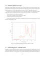
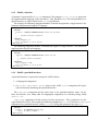
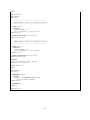
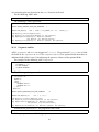
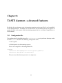
Figure 1.1: Automatically generated GUIs for TM/TCs
1.4
Automatic GUIs for telemetry and telecommands
Since many parts of TASTE were build under the close supervision of the European Space Agency
(ESA), the handling of telemetries and telecommands is completely automated. By simply marking a subsystem with the appropriate tag, TASTE automatically generates a complete GUI that
allows interactive, real-time monitoring and control of the system. By piping telemetry data to
GnuPlot, it also allows easy graphical monitoring (see figures 1.1, 1.3).
1.5
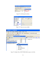
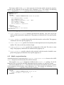
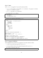
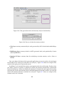
Automatic run-time monitoring of TM/TCs via MSCs
Using the tracer.py and tracerd.py utilities, the automatically generated TASTE GUIs message exchanges (i.e. telemetry and telecommands) can be monitored in real-time, via the freely
available PragmaDev MSC Tracer6 . This allows for direct and simple monitoring of the communications channels between the TASTE GUIs and the main applications (see figure 1.2).
6
MSC Tracer available at http://www.pragmadev.com/product/tracing.html.
9
Figure 1.2: Automatic monitoring of TM/TCs via MSC Tracer
10
1.6
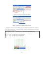
Automatic Python test scripts
Testing the (usually complex) logic inside space systems requires big regression checking suites.
TASTE tools automatically create Python bridges that offer direct access to the contents of the
ASN.1 parameters, as well as direct runtime access to the TM/TCs offered by the system.
All that the user needs to do to create his set of regression checks, is to write simple Python
scripts, that exercise any behavioural aspect of the system. For example, a scenario like this:
when I send a TC with value X in param Y,
then I expect a TM after a max waiting of Z seconds,
with the value K in the incoming param L
...can be expressed in less than 10 lines of Python code, with an order of magnitude less work
than the corresponding C code.
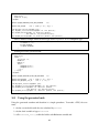
Figure 1.3: Graphical monitoring of telemetry data in real-time
1.7
Acknowledgements - who did TASTE
TASTE is a complex tool-chain made of a number of components that were developed by various
people and various companies. This section contains a list of TASTE authors and contributors. It
may not be exhaustive, as many partners are regularly contributing to the toolchain development.
11
1. ESA (European Space Agency) is responsible for TASTE technical lead and management,
and for the buildsupport, polyorb-hi-c, rtems port, tastegui tools, etc.
2. SEMANTIX is responsible for the TASTE disribution, the design and implementation of the
data modelling tools based on ASN.1, the integration, validation and release of the TASTE
virtual machine, the vhdl, msc, gnuplot support, etc.
3. ELLIDISS is responsible for the development of the interface and deployment view GUI
editors.
4. ISAE is responsible for the polyorb-hi-ada and ocarina tools.
5. TELECOM-PARISTECH is the original developer of the ocarina and polyorb tools
6. UPM is developing the gnatforleon runtime (Ada runtime for LEON processors), the original
AADL to MAST convertor, and some drivers (serial, spacewire) for the Ada runtime.
7. PRAGMADEV provides the free MSC tracer that can be used to trace communication within
the blocks of the system.
8. ASSERT partners provided inputs to the overal process (see ASSERT website for more information)
12
Chapter 2
Taste concepts
2.1
The TASTE steps in building an application
System
Models
AADL
Data Models
AADL
Data Models
(ASN.1)
Lustre definitions
SDL definitions
SCADE
modeling
ObjectGeode
modeling
ASN.1 compiler
C Code
C Code
Behavior
C Code
Encoder/Decoder
Data Structures
“Glue”
Data Structures
Behavior
“Glue”
PolyORB Container
Data Structures
PolyORB Container
Platform (Leon/ORK, Leon/RTEMS or Linux)
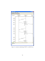
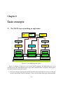
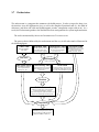
Figure 2.1: Data Modeling with ASN.1
Figure 2.1 displays a high level view of how TASTE integrates the individual pieces of an
overall system. The yellow blocks depict stages where manual labour is required, and the green
ones depict machine-generated entities.
1. The process begins with manual specification of the data models for the messages exchanged
between subsystems (TASTE "Functions"). This is where details about types and constraints
13
of the exchanged messages are specified. To be usable from within the system AADL specifications, these message definitions are translated into AADL data definitions. These definitions are in turn used by the system designer (the one doing the high-level interface modeling): they are referenced inside the high level design of the system, when describing the
system’s interfaces. The Interface View in AADL explicitely describes the interfaces, in terms
of the available ASN.1 types.
2. The actual functional modeling of subsystems is next - but before it begins, the exchanged
messages’ descriptions are read by TASTE, and semantically equivalent definitions of the
data messages are automatically created for each modeling tool’s language (e.g. Lustre definitions for SCADE modeling, Simulink definitions for MATLAB/Simulink modeling, etc).
This way, the teams building the individual subsystems are secure in their knowledge that
their message representations are semantically equivalent and that no loss of information
can occur at Interface borders.
3. Functional modeling is then done for the individual subsystems. The modeling uses the data
definitions as they were generated in step 2. In fact, the modelling has absolutely no work
to do in terms of interface specification: the interfaces are 100% automatically generated
by TASTE, in so-called "skeleton" projects. If the interface view specifies that a Function is
written in SCADE, a SCADE skeleton will be generated by TASTE, and the user fills-in the
"meat" of the calculation. If the interface view specifies that a Function is written in C, then
TASTE generates a .h/.c declaration/definition of the interface, and the user just fills-in the
details. Etc.
4. When functional modeling is completed, the modeling tools’ code generators are put to
use, and C code is generated (this step does not exist if the Function is manually written
in C or Ada). Modeling tools generate code in different ways; even though (thanks to step
2) the data structures of the generated code across different modeling tools are carrying
semantically equivalent information, the actual code generated cannot interoperate as is;
error-prone manual labour is required to “glue” the pieces together. This is the source of
many problems1 , which is why ASN.1 is used in TASTE: by placing it as the center of a star
formation amongst all modeling tools, the “glue-ing” can be done automatically.
5. TASTE automatically invokes the ASN.1 compiler to create encoders and decoders for the
messages.
6. TASTE automatically creates “glue” code that maps (at runtime) the data from the data structures generated by the modeling tools to/from the data structures generated by the ASN.1
compiler.
7. Code from the ASN.1 compiler, code from the modeling tools and “glue” code are compiled
together inside PolyORB-Hi containers, generated by Ocarina.
8. The generated binaries (OpenRavenscar / RTEMS / Linux) are executed.
1
Lost satellites being one of them.
14
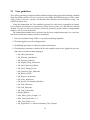
2.2
Taste guidelines
Taste aims at providing a Component-Based Software Engineering approach by defining a methodology that builds systems correct by construction: users define the functional aspects of the system
using containers, functions, interfaces and describe their allocation on the hardware (using a socalled Deployment view).
Using this information, the Taste toolchain generates the code that is responsible for component execution. It instantiates system resources (data, mutexes, tasks, etc.) and allocates software
on them. As is the case for every real-time system, the generated systems enforce a computational
model as well as several restrictions.
The computational model that is checked is the Ravenscar computation model. So, every function of the system must comply with these restrictions:
1. Tasks are scheduled using a FIFO via a priority scheduling algorithm.
2. The locking policy uses the ceiling protocol.
3. No blocking operations are allowed in protected functions
4. The following restrictions as defined in the Ada compiler must also be applied to any functions that are written in other languages:
• No_Abort_Statements
• No_Dynamic_Attachment
• No_Dynamic_Priorities
• No_Implicit_Heap_Allocations
• No_Local_Protected_Objects
• No_Local_Timing_Events
• No_Protected_Type_Allocators
• No_Relative_Delay
• No_Requeue_Statements
• No_Select_Statements
• No_Specific_Termination_Handlers
• No_Task_Allocators
• No_Task_Hierarchy
• No_Task_Termination
• Simple_Barriers
• Max_Entry_Queue_Length => 1
• Max_Protected_Entries => 1
• Max_Task_Entries => 0
• No_Dependence => Ada.Asynchronous_Task_Control
15
• No_Dependence => Ada.Calendar
• No_Dependence => Ada.Execution_Time.Group_Budget
• No_Dependence => Ada.Execution_Time.Timers
• No_Dependence => Ada.Task_Attributes
In addition, the following restrictions must also be enforced by each component used in Taste
programs:
1. No controlled types. In Ada, this is provided by pragma Restrictions (No_Dependence
=> Ada.Finalization);
2. No implicit dependency on object oriented features. Ada provides this restriction with
pragma Restrictions (No_Dependence => Ada.Streams)
3. No exception handler shall be defined. Ada provides this restriction with: pragma Restrictions
(No_Exception_Handlers)
4. No unconstrained objects, including arrays - and forbidden string concatenation. Ada provides this restriction with: pragma Restrictions (No_Secondary_Stack)
5. Do not use allocation. Ada provides this restriction with pragma Restrictions (No_Allocators)
6. All access/references to variables must be explicitly typed. Ada check that using the restriction: pragma Restrictions (No_Unchecked_Access)
7. Avoid explicit dispatch. Ada provides this features with pragma Restrictions (No_Dispatch)
8. Do not use input/output mechanisms. Ada provides this feature/restriction with: pragma
Restrictions (No_IO)
9. Do not use recursion. Ada provides this feature with: pragma Restrictions (No_Recursion)
10. As for allocation, memory deallocation must be checked. This is provided in Ada with
pragma Restrictions (No_Unchecked_Deallocation)
2.3
Main components
Taste is centered around the following elements:
1. The Data View describes the data definitions of your system. It defines data types using the
ASN.1 standard2 .
2. The Interface View details the system from a purely functional point of view. This view
describes the functions performed by the system and the data types that they handle. Data
associated with the functions rely on the Data View definitions.
2
Read about ASN.1 on http://en.wikipedia.org/wiki/ASN.1
16
3. The Deployment View defines how system functions are bound on the hardware. It defines
the underlying architecture (processors, devices, memories, etc.) and allocates each function
on these hardware components.
4. The Concurrency View represents software and hardware aspects of the system. It contains
tasks, data and communication between system artifacts (tasks, processes, subprograms,
etc.). The concurrency view is automatically generated from the interface view and the
deployment view by the buildsupport tool (see section 3.6). Thus, all the mapping rules
that transforms system interfaces and deployment information are included in this tool that
automatically generates a complete description of the system.
Finally, the Concurrency view provides a complete view of the system, giving the ability
to analyze it using validation tools. The TASTE-CV tool 3.2 provides such functionnality,
linking the concurrency view with schedulability analysis tool.
2.4
Development process overview
Once designers have specified the different views (Data, Interface, and Deployment), the Taste
tools automatically generate code that implements the system. In particular, they generate data
definitions in whatever language is used to describe the functionality of each system (SCADE
models, Simulink models, C header files, Ada .ads files, etc) as well as “skeleton” projects (.xscade
files, .mdl files, .c/.adb files, etc) that include the formal specifications of interfaces, with empty
implementations. The tools also create the code that connects function interfaces with their callers
(they can do that, because the Interface View includes these connections). Finally, they produce the
code required to execute the functions on top of Real-Time operating systems (such as RT-Linux,
RTEMS, etc.).
Finally, these code generators auto-configure and deploy the system so that you don’t have
to write additional code and introduce potential errors. Network addresses, drivers and all other
deployment code is automatically generated.
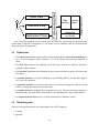
The whole process is illustrated in the figure below: the user defines the Data View, the Interface View and the Deployment View. Then, appropriate tools (code generators) automatically
produce data handling functions, interaction code with the functional code as well as deployment
and configuration code to execute the system on top of an RTOS.
17
Interface View
Deployment View
Data
Function
Handling Mgmt
Generated
middleware
Operating System
Application
Code generators
Data View
(e.g: RTEMS)
As a result, this approach creates systems that are correct by construction. By generating the
system from a high-level description, we can make several validation and/or verification and
ensure designers’ requirements.
2.5
Definitions
• The Concurrency View is automatically generated through the vertical transformation process. It creates resources (tasks, mutexes, etc.) of the system and associates functions to
them.
• The Data View contains the definition of all data types used in the functions’ interfaces,
using the ASN.1 notation.
• The Interface View defines the functions of your system with their respective interfaces and
data ports.
• A periodic interface is executed according to a predefined period. It also has other properties, such as the deadline.
• A protected interface is executed exclusively by one entity, meaning that only one thread
can be executing this function at the same time.
• A sporadic interface is triggered by a reception of an event. The time between two events is
bounded and is specified with a value known as the Minimul Inter-Arrival Time (MIAT).
• An unprotected interface may be executed concurrently by different entities.
2.6
Modeling rules
You have four operation kinds (that correspond to the AADL property:
1. Periodic
2. Sporadic
18
3. Protected/unprotected
So, when deciding what to use for a function’s provided interfaces (PIs), we must take into
consideration that the Functions can have PIs that can currently belong to only one of two caregories:
1. Sporadic and Cyclic
• Sporadic can’t have OUT params, since they are async (caller doesn’t wait for them to
return, so no results can be returned from their invocation).
• Each Sporadic/Cyclic PI gets one thread. They DONT run in the calling thread context.
• There is automatic mutual exclusion between all PIs that are Sporadic and/or Cyclic
inside the same Function, via a protected object. To be more exact, Sporadic and Cyclic
PIs get their own threads, but when they are called and need to execute their actual
implementations (user code), the actual user code call is done from inside a protected
object - and thus, mutual exclusion takes place (only one Sporadic/Cyclic can be active
at any time).
• Cyclic don’t have IN or OUT params, they are called periodically
• Sporadic can only have ONE IN param, carrying all the data they need.
• Sporadic can in fact be considered a special kind of Cyclic, since they have MIAT (Minimum Inter-Arrival Time)
2. Protected and Unprotected
• run in the calling thread context
• can have multiple IN and OUT params
• are synchronous, that is the calling thread waits for them to return (since they have
OUT values that it wants to read).
• Protected PIs use an Ada protected object to guarantee mutual exclusion between a
Function’ s protected PIs, so you use them whenever the Function’s PIs share state
and would have issues with multiple calling threads entering two or more of them
simultaneously and messing up the shared state.
• Unprotected can read/write anything they want, so they allow the calling context to
enter at will.
• Protected and Unprotected can co-exist inside a Function (since you may have functionality that has no state-dependencies).
19
20
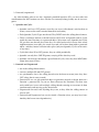
Chapter 3
Overview of the Taste toolset
3.1
Labassert
Labassert is a graphical tool developed by E LLIDISS T ECHNOLOGIES to edit the Interface and
Deployment views. Labassert works on Windows and Linux.
However, this tool is now considered as deprecated and is replaced by three programs : TASTEIV, TASTE-DV and TASTE-CV.
3.2
TASTE toolset (TASTE-IV, TASTE-DV and TASTE-CV)
TASTE-IV is the tool used to edit the interface view of your system: it provides functionnalities to describe system functions, their parameters and in which language they are implemented.
TASTE-DV is the editor for the deployment view, providing functionnalities to describe how system functions are allocated to processing resources (CPU, network, etc.). Finally, TASTE-CV is
the concurrency view editor. It is used to perform schedulability analysis and simulates system
execution, detecting potential system errors that can be risen at run-time (deadlocks, etc.).
3.3
ASN.1 generators
ASN.1 generators consist in tools that creates data types and run-time data translation "bridges"
(between e.g. SCADE/KCG code and Simulink/RTW code) from the ASN.1 type descriptions.
These tools are developed by S EMANTIX I NFORMATION T ECHNOLOGIES.
3.4
Ocarina
Ocarina is a toolchain to manipulate AADL models. It runs on Windows, Linux and Mac OS X
and proposes code generation features that produce code that targets real-time middleware such
as PolyORB.
21
3.5
PolyORB-HI
PolyORB-HI is the middleware that interfaces generated code from AADL models to the RTOS.
It maps the primitives of the generated code to the ones offered by the operating system, in order
to ensure their integration. PolyORB-HI provides the following services to the generated code:
• Tasking: handle tasks according to their requirements (period, deadline, etc.)
• Data: define types and locking primitives
• Communication: send/receive data on the local application and send them to the other
nodes of the distributed system.
• Device Drivers: interact with devices when a connection uses a specific bus.
There are two versions of PolyORB-HI: one for Ada and one for C. They are described in the
following paragraphs.
3.5.1
Ada version
The Ada version can be used on top of Linux, RTEMS and Open Ravenscar Kernel (ORK). It
enforces the Ravenscar profile and has been successfully tested on LEON and x86 targets.
3.5.2
C version
The C version can be used on top of Linux, RT-Linux, Maemo and RTEMS. It works on LEON,
ARM, PowerPC and x86. It was successfully tested on native computers (x86 with Linux), LEON
boards (with RTEMS), ARM (with DSLinux and Maemo).
3.6
Buildsupport
Buildsupport provides several functionalities:
1. It generates the concurrency view from the interface and deployment views. The result
is an AADL models that is subsequently processed by Ocarina to generate and build the
system in C or Ada.
2. It creates skeletons (for each Function’s target environment, e.g. .xscade files for SCADE
Functions, .h/.c files for C Functions, .ads/.adb for Ada Functions, etc) that include the
complete specifications of interfaces, with empty implementations.
This part assumes that we have a description of all Archetypes, meaning how we convert the
interface and deployment view into a concurrency view that describe tasking concerns. It means
that this tool contain all relevant information to map a cyclic/sporadic/protected/unprotected
interface into thread and data.
!!! FIXME !!!
TO BE COMPLETED BY MAXIME
22
3.7
Orchestrator
The orchestrator is a program that automates the build process. It takes as input the data view,
the interface view, the deployment view, as well as the complete Functional code (i.e. the filled-in
skeletons), and then calls each tool (buildsupport, ocarina, compilation scripts and so on). As a
result, the Orchestrator produces the final binaries that correspond to the system implementation.
The tool is maintained by S EMANTIX I NFORMATION T ECHNOLOGIES.
The process that is followed by the orchestrator and the way it calls other tools is illustrated in
the following figure.
Data View
Data type definitio
with ASN1
asn1scc
Interface view
Deployment view
Describe system functions,
their parameters and
implementation language
Specify deployment of system
functions on the hardware
(processors, bus, ...)
Functional code
Implementation of functions
with traditional code (C, Ada)
or application models
(SCADE, Simulink, SDL, etc.)
Buildsupport
Data types code
Contain data types definitio
in the implementation
language (C, Ada, ...)
Concurrency view
Glue code
System description that contains
tasks, data and inter-process
connections
Contain necessary code constructs
to distribute application data over
the nodes of the distributed system.
Ocarina
Architecture code
Code that creates tasks, protected data,
enable data distribution, runtime
services that supports system functions, and
configure the underlying operating syste
Compilation
Implementation binary
Executable binary that runs on the
target architecture (x86 with Linux,
LEON with RTEMS or ORK, etc.)
23
3.8
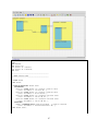
TASTE GUI
The Taste GUI is a program which purpose is to assist the system designer in the use of the different tools of Taste. It provides a convenient interface to design the different views of your system
(data, interface and deployment).
The TASTE GUI is available in the Taste virtual machine (VM), as well as an independent
package. An example of the interface is shown in the following picture.
The program let you define the view of your system but also let you edit their definition using a
text editor. Finally, it provides some functionnalities to deploy generated applications and choose
the runtime used (PolyORB-HI-C, PolyORB-HI-Ada, etc.).
3.9
TASTE daemon (tasted)
The TASTE daemon is a program designed to ease the execution of generated applications. It was
especially designed to interact with TASTE GUI (as detailed in section 14.6) : once system designers have successfully built their systems, they can automatically execute them on boards. As
the TASTE toolset can produced applications for systems with different architectures and requirements, it is sometimes difficult to deploy them altogether. The TASTE daemon aims at facilitate
this deployment and execution step.
The TASTE daemon runs on a machine (potentially the same machine as the host development)
and listen for incoming request. Then, the TASTE GUI tool sends generated applications and
receives execution output from the daemon.
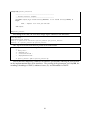
Generated applications
binaries
TASTE GUI
TASTE daemon
Application
execution output
24
3.10
Additional tools
The Taste process relies on third-party tools to either model functions; or RTOS to execute the final
systems. It is the user responsibility to get a valid license and install them. Chapter 7 illustrates
how to import your models and the code generated from this tools in the Taste toolchain.
The Taste toolchain supports the following tools:
• Simulink / Real Time Workshop v7.0
• Scade / KCG v6.1.2
• SDL tools ObjectGeode v4.2.1 and PragmaDev RTDS v4.12
In addition, the Taste toolchain can generate binaries for the following platforms:
• RTEMS from OAR Technologies, version 4.8.0,
• ORK+ from the Universidad Politécnica de Madrid, version 2.1.1,
• Linux and most POSIX-compatible variants, including embedded ones.
25
26
Chapter 4
Installation and upgrade of the TASTE
toolchain
There are two ways to use the TASTE toolchain : a regular installation on a Linux system and
use of a virtual machine. The virtual machine system provides a complete environment with
a predefined Linux installation that contains everything. The installation on your Linux system
gives you the ability to use the toolchain with your day-to-day environment. It is more convenient
in many ways but the TASTE developpers does not provide official support on such installation.
Support is provided only for users that are using the tools within the VM. Indeed, the use
of the same architecture ease bug detection and provide a similar environment for both users
and developers, and so, is more convenient to reproduce bugs related to the toolchain (and not
environment of the user).
4.1
Installation of the virtual machine
The Virtual Machine system needs to install a software able to execute VMWare image. For that
purpose, you can download VMWare Player at the following address: http://www.vmware.
com/products/player.
Then, once installed, you need to download the TASTE virtual machine available at this address: http://download.tuxfamily.org/taste/taste-vm.tar.gz.
Finally, launch VMWare Player, open the TASTE VM so that you can start to use the tools in
the configured environment.
4.2
4.2.1
Installation on your own Linux distribution
Distributions
At this time, we support the following distributions:
• Debian
• Ubuntu
27
• Mandriva
4.2.2
Using the installation script
We provide an installation script that ease the installation and deployment of our tools. You can
find the installation program at http://download.tuxfamily.org/taste/taste-installer.
sh.
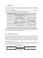
The installation program requires you have the program/package dialog installed on your
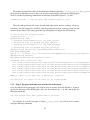
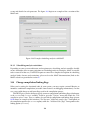
system. If it is not installed, use the package manager of your distribution to install it. Then,
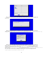
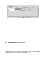
invoke the program, you would see the following screen.
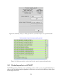
At first, you are asked to provide the installation directory. This directory must exist on your
system and you must be allowed to write in it.
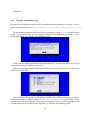
Then, you can choose which packages to install on your system. We advise you to choose and
install every TASTE tools.
As the TASTE graphical tools are not directly available on the internet and require you download them manually on Ellidiss website (http://www.ellidiss.com), you are asked to provide the archive file of the program of you want to install them. To do so, a file dialog chooser will
ask you to provide the location of the TASTE tools, as shown in the following picture.
28
Then, the installation process starts, download software archive on the internet, compile and
install them.
Finally, if everything runs fine, the following screen would appear. If some error was raised, a
dialog error will appear. In that case, you can see the installation log in the file /tmp/taste-installer-log.
Finally, TASTE tools requires that you defined some environment variables. The installer automates this process by creating a shell-script that contains all new environment variables. It is located in the installation directory, with the name taste-env.sh. So, if you installed the tools under the directory /home/user/local/, you are required to use the file /home/user/local/taste-env.sh.
This can be done automatically by adding the following line in your shell configuration file:
source /path/to/installation/taste-env.sh
29
Assuming you installed the tools in /home/user/local/, you will add the following line in
your shell configuration file (for example $HOME/.bashrc):
source /home/user/local/taste-env.sh
4.3
Upgrade within the virtual machine
To upgrade the tools to the latest version within the virtual machine, invoke the script UPDATE-TASTE.sh.
Open a terminal and invoke the command. Once called, it downloads the latest version of each
tool and install them in their appropriate directory.
4.4
Upgrade on your own Linux distribution
If you want to upgrade the tools on your own installation, you need to run the installation program
again. Fortunately, the installation program is already installed when you run it for the first time.
In that case, you just have to invoke the command taste-installer on your system. It will
restart the installation program and will use the installation directory you used at installation time
to upgrade the tools.
30
Chapter 5
Using ASN.1
ASN.1 is a standardized notation to represent data types. An overview of this standard can be
found on http://www.itu.int/ITU-T/asn1/introduction/index.htm. For readers that
are interested in ASN.1 and want to learn the language, a tutorial can be found here: http:
//www.obj-sys.com/asn1tutorial/asn1only.html.
All data types exchanged between Function interfaces are described using ASN.1. Data types
definitions constitute the Data View. These types are then used by function interfaces, to specify
the parameter types in a standardized way. On the implementation side, code generators map the
ASN.1 types into language-specific definitions (e.g. SCADE definitions, or Simulink/RTW definitions, or Ada/C definitions, etc) and create functions to exchange these types between different
environments, regardless of their specific characteristics (CPU models, endianness, word sizes,
etc).
If you are not familiar with ASN.1, an easy way to get acquainted is to follow the tutorial on
http://www.obj-sys.com/asn1tutorial/asn1only.html.
31
32
Chapter 6
Using the graphical tool (The TASTE
toolsuite)
6.1
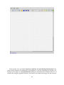
The interface view: TASTE-IV
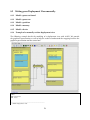
The interface view provides the ability to describe system functions with their provided and required interfaces. The picture below gives an example of the Interface View.
33
In the interface view, you define containers, functions and provided/required interfaces. The
picture below illustrates the definition of two containers, each one containing one function. The
function on the right uses a Provided Interface (PI) that is required by the function on the left. To
describe that using the graphical interface, the interfaces are connected using a line and an arrow.
34
When you define an interface, you have to define its characteristics (periodic, sporadic, arrival
time, etc.). For that, right-click on the provided interface, a menu will open. Choose Properties.
35
Then, a new window gives you the ability to define the characteristics of the Provided Interface, as shown in the following picture.
In the same window, you can also specify the data types of the interface parameters, as illustrated in the following picture. Please also note that the types you specify in this window are
defined in your Data View (your ASN.1 type definitions).
36
6.2
The deployment view: TASTE-DV
The deployment view editor is a graphical tool that provides the ability to edit the AADL definition of your architecture. A screenshot of the program follows:
37
You can then add hardware components in your architecture. It mainly consists of adding
computer boards with their processors and memories. Partitions are then added, that will host
the functions from your functional view. You can connect partitions (and thus, functions) by
adding buses to your architecture and by connecting the processors with these buses.
38
Note that when you add/specify a driver in the deployment view, it has to be configured. For
example, for a network card that uses the TCP/IP protocol, you have to specify the IP address
and the port used to receive incoming data. For serial port, you have to specify the corresponding
device (/dev/ttyS0, etc.) as well as the speed of the port (115200 bauds, etc ..).
This configuration is detailed in this documentation, within the PolyORB-HI-C and PolyORBHI-Ada part. For PolyORB-HI-C, section 15.3.3 provides all required information.
6.3
The concurrency view: TASTE-CV
TASTE-CV has the ability to edit the concurrency view generated by buildsupport. It provides
schedulability analysis functionalities to assess system scheduling feasability as well as scheduling
simulation. Using this tool, we could be able to know if the deadlines of your tasks will be met
and also inspect the behavior of your system, including its potential problems (such as deadlocks).
To assess scheduling feasability, TASTE-CV embedds the Cheddar scheduling analyzer. It pro39
cesses AADL models and transform them into a suitable representation for Cheddar. The Cheddar
output is based in scheduling theory and feasability tests. Readers interested in scheduling tests
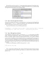
and scheduling theory could refer to articles listed on the official Cheddar website (see D for web
links).
To simulate system scheduling, TASTE-CV relies on the Marzhin scheduling simulator. Marzhin
shows the simulation of the execution of each tasks (running, waiting for a resource, sleeping, . . . )
as well as the state of shared data (locked, unlocked, . . . ).
6.3.1
Marzhin symbols
The following symbols are usedby Marzhin within the simulation window:
• # : Thread state none
• | : Thread state running
• _ : Thread state ready
• ˜ : Thread state awaiting resource
• * : Thread state awaiting return
• . : Thread state suspended
• O : Data state - occupied
• < : Get resource
• > : Release resource
• ! : Send Output or Subprogram Call
• 1..9 : Queued events or call requests
• + : More than 9 queued events or call requests
6.3.2
Marzhin assumptions about system behavior
To simulate your system, Marzhin makes the following assumptions about the behavior of your
system:
• An AADL data component in the Concurrency View without specific properties is considered as protected with no specific protocol (no priority inversion).
• An AADL data component can specifies the following protection mechanisms using the
Concurrency_Control_Protocol property:
1. IPCP (value Immediate_Priority_Ceiling_Protocol)
2. PCP (value Priority_Ceiling_Protocol)
40
• All out ports from the threads send data when the thread completes its task. The tool considers that the thread completes its job when the upper bound of its execution time is reached.
It ensures that out ports are trigerred.
• Thread components that specifies their behavior using the Behavior Annex of the AADL don’t
send anything on their out ports when they complete their job. Instead, the tool expects that
the system designer specifies sending time using the Behavior Annex.
Finally, to be able to process both scheduling feasability tests as well as scheduling simulation,
you must check that all timing requirements of the functional aspects of your system are described
(period, deadline, execution time, etc.).
41
42
Chapter 7
Creating Functions, using modelling
tools and/or C/Ada
7.1
Common parts
The TASTE process integrates the code for the system’s Functions into working executables (for
Linux or Leon/RTEMS or Leon/ORK). It therefore depends on the provision of the functional
code for the user’s subsystems (Functions). This provision is done either via code generated by
a modelling tool (SCADE, Simulink, ObjectGeode, PragmaDev) or via manually written code (C,
Ada).
Let’s see how things work in each of these categories.
7.2
SCADE-specific
If a Function is coded in SCADE, then the corresponding AADL part of the Interface View will
contain something like this:
SYSTEM p a s s i v e _ f u n c t i o n
FEATURES
compute : IN EVENT PORT
{
Compute_Entrypoint => " compute " ;
A s s e r t _ P r o p e r t i e s : : RCMoperation => SUBPROGRAM myLib : : compute ;
A s s e r t _ P r o p e r t i e s : : RCMoperationKind => u n p r o t e c t e d ;
};
END p a s s i v e _ f u n c t i o n ;
SYSTEM IMPLEMENTATION p a s s i v e _ f u n c t i o n . o t h e r s
PROPERTIES
Source_Language => SCADE6 ;
END p a s s i v e _ f u n c t i o n . o t h e r s ;
...
SUBPROGRAM compute
FEATURES
my_in : i n PARAMETER DataView : : T_POS
{ A s s e r t _ P r o p e r t i e s : : encoding => UPER ; } ;
r e s u l t : out PARAMETER DataView : : T_POS
{ A s s e r t _ P r o p e r t i e s : : encoding => NATIVE ; } ;
43
PROPERTIES
Compute_Execution_Time => 1ms . . 1 ms ;
END compute ;
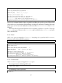
In this example, a Function called passive_function contains a provided interface called
compute. This interface has one input parameter and one output parameter, which, in this example, are both of type T_POS. This type is described in the ASN.1 grammar:
...
T−POS : : = CHOICE {
l o n g i t u d e REAL( − 1 8 0 . 0 . . 1 8 0 . 0 ) ,
latitude
REAL( − 9 0 . 0 . . 9 0 . 0 ) ,
h e i g h t REAL( 3 0 0 0 0 . 0 . . 4 5 0 0 0 . 0 ) ,
subTypeArray SEQUENCE ( SIZE ( 1 0 . . 1 5 ) ) OF TypeNested ,
label
OCTET STRING ( SIZE ( 5 0 ) ) ,
intArray
T−ARR,
...
}
TypeNested : : = SEQUENCE {
...
}
T−ARR : : = SEQUENCE ( SIZE ( 5 . . 6 ) ) OF INTEGER ( 0 . . 3 2 7 6 7 )
This type is a complex one, referencing other types, and containing arrays (SEQUENCE OFs),
too. Let’s see how these two inputs - the ASN.1 grammar and the Interface view, are combined
during TASTE development.
Invoking asn2dataModel.py on the ASN.1 grammar:
bash$ cd ScadeExample
bash$ l s − l
total 9
drwxr−xr −x 2 a s s e r t a s s e r t
88 May 17 14:20 . /
drwxr−xr −x 37 a s s e r t a s s e r t 4608 May 17 14:21 . . /
−rw−r −−r −− 1 a s s e r t a s s e r t 2182 May 17 14:20 DataTypesFull . asn
bash$ asn2dataModel . py −toSCADE6 DataTypesFull . asn
bash$ l s − l
t o t a l 57
drwxr−xr −x 2 a s s e r t a s s e r t
128 May 17 14:23 . /
drwxr−xr −x 37 a s s e r t a s s e r t 4608 May 17 14:21 . . /
−rw−r −−r −− 1 a s s e r t a s s e r t 2182 May 17 14:20 DataTypesFull . asn
−rw−r −−r −− 1 a s s e r t a s s e r t 46321 May 17 14:23 DataTypesFull . xscade
The model mapper generates a .xscade file - and this file is directly importable in SCADE.
The next steps show how:
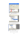
1. A new project is created in SCADE (see 7.1)
2. The default libraries are removed - and "Finish" is clicked (see 7.2)
3. The project opens - FileView is selected (see 7.3)
4. The TASTE-generated .xscade file is inserted (see 7.4)
5. Going back to "Framework", the ASN.1 types are now visible (and usable) in SCADE (see
7.5)
44
Figure 7.1: Create a new SCADE project
Figure 7.2: Remove default libraries
45
Figure 7.3: Select FileView
Figure 7.4: Add TASTE-generated .xscade file
Figure 7.5: Types are now available
46
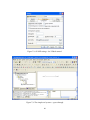
Figure 7.6: Interface skeleton generated by TASTE
Figure 7.7: SCADE settings
47
Figure 7.8: SCADE settings - Set "Global context"
Figure 7.9: The simplest of systems - a pass-through
48
This allows the user to use the ASN.1 types in his SCADE Function. However, TASTE offers
more than this - it creates the SCADE "skeleton", with the parameters of the Function’s interface
already filled in:
bash$ b u i l d s u p p o r t −gw −g l u e − i i n t e r f a c e v i e w . a a d l −c deploymentview . a a d l −d DataTypesFull . a a d l
...
bash$ l s − l
t o t a l 88
drwx−−−−−− 2 a s s e r t a s s e r t
80 May 17 14:38 Backdoor
drwx−−−−−− 2 a s s e r t a s s e r t
200 May 17 14:38 ConcurrencyView
−rw−r −−r −− 1 a s s e r t a s s e r t 22393 May 17 14:35 DataTypesFull . a a d l
−rw−r −−r −− 1 a s s e r t a s s e r t 2182 May 17 14:20 DataTypesFull . asn
−rw−r −−r −− 1 a s s e r t a s s e r t 46321 May 17 14:23 DataTypesFull . xscade
−rw−r −−r −− 1 a s s e r t a s s e r t
126 May 17 14:38 b u i l d −sample . sh
drwx−−−−−− 2 a s s e r t a s s e r t
312 May 17 14:38 c y c l i c _ f u n c t i o n
−rw−r −−r −− 1 a s s e r t a s s e r t 1018 May 17 14:37 deploymentview . a a d l
−rw−r −−r −− 1 a s s e r t a s s e r t 2242 May 17 14:37 i n t e r f a c e v i e w . a a d l
drwx−−−−−− 2 a s s e r t a s s e r t
216 May 17 14:38 p a s s i v e _ f u n c t i o n
bash$ cd p a s s i v e _ f u n c t i o n
bash$ l s − l
t o t a l 16
−rw−r −−r −− 1 a s s e r t a s s e r t 368 May
−rw−r −−r −− 1 a s s e r t a s s e r t 740 May
−rw−r −−r −− 1 a s s e r t a s s e r t 2302 May
−rw−r −−r −− 1 a s s e r t a s s e r t 873 May
17
17
17
17
14:38
14:38
14:38
14:38
mini_cv . aadl
p a s s i v e _ f u n c t i o n . xscade
p a s s i v e _ f u n c t i o n _ w r a p p e r s . adb
p a s s i v e _ f u n c t i o n _ w r a p p e r s . ads
Another .xscade file is generated - containing the skeleton for the SCADE Operator passive_function.
By importing this file as well (as before, from the FileView, right-click/insert files), the project
skeleton is now available - see 7.6.
In order to be able to use the KCG (SCADE’s code generator) output from TASTE, the user
must select "Global context" in the KCG options - see 7.7 and 7.8.
After this, we can fill-in the skeleton - for example, we can create the simplest of systems (since
both input and output are of the same type, T_POS): a pass-through (7.9).
Invoking KCG, will generate our code - which we place inside a .zip file, that must contain a
directory with the same name as our SCADE Function (passive_function):
bash$
bash$
bash$
bash$
bash$
mkdir package
cd package
mkdir p a s s i v e _ f u n c t i o n
cp −a / path / t o / kcg / generated / f i l e s / ∗ p a s s i v e _ f u n c t i o n /
z i p −9 − r p a s s i v e _ f u n c t i o n . z i p p a s s i v e _ f u n c t i o n /
This .zip file is the one that must be passed to the orchestrator, when using a SCADE subsystem:
bash$ "$DMT/OG/ a s s e r t −b u i l d e r −o c a r i n a . py " \
−f \
−o b i n a r y . l i n u x \
−a . / DataView . asn \
−i . / InterfaceView . aadl \
−c . / DeploymentView . a a d l \
...
−S p a s s i v e _ f u n c t i o n : / path / t o / p a s s i v e _ f u n c t i o n . z i p
49
Figure 7.10: Creating a Simulink/RTW function
7.3
Simulink-specific
If a Function is coded in Simulink, then the TASTE editor must be used to properly select the
Function’s "language" field, as depicted in Figure 7.10. The corresponding AADL part of the
Interface View will then contain something like this:
SYSTEM p a s s i v e _ f u n c t i o n
FEATURES
compute : IN EVENT PORT
{
Compute_Entrypoint => " compute " ;
A s s e r t _ P r o p e r t i e s : : RCMoperation => SUBPROGRAM myLib : : compute ;
A s s e r t _ P r o p e r t i e s : : RCMoperationKind => u n p r o t e c t e d ;
};
END p a s s i v e _ f u n c t i o n ;
SYSTEM IMPLEMENTATION p a s s i v e _ f u n c t i o n . o t h e r s
PROPERTIES
Source_Language => S i m u l i n k ;
END p a s s i v e _ f u n c t i o n . o t h e r s ;
...
SUBPROGRAM compute
FEATURES
my_in : i n PARAMETER DataView : : T_POS
{ A s s e r t _ P r o p e r t i e s : : encoding => UPER ; } ;
50
r e s u l t : out PARAMETER DataView : : T_POS
{ A s s e r t _ P r o p e r t i e s : : encoding => NATIVE ; } ;
PROPERTIES
Compute_Execution_Time => 1ms . . 1 ms ;
END compute ;
In this example, a Function called passive_function contains a provided interface called
compute. This interface has one input parameter and one output parameter, which, in this example, are both of type T_POS. This type is described in the ASN.1 grammar:
...
T−POS : : = CHOICE {
l o n g i t u d e REAL( − 1 8 0 . 0 . . 1 8 0 . 0 ) ,
latitude
REAL( − 9 0 . 0 . . 9 0 . 0 ) ,
h e i g h t REAL( 3 0 0 0 0 . 0 . . 4 5 0 0 0 . 0 ) ,
subTypeArray SEQUENCE ( SIZE ( 1 0 . . 1 5 ) ) OF TypeNested ,
label
OCTET STRING ( SIZE ( 5 0 ) ) ,
intArray
T−ARR,
...
}
TypeNested : : = SEQUENCE {
...
}
T−ARR : : = SEQUENCE ( SIZE ( 5 . . 6 ) ) OF INTEGER ( 0 . . 3 2 7 6 7 )
This type is a complex one, referencing other types, and containing arrays (SEQUENCE OFs),
too. Let’s see how these two inputs - the ASN.1 grammar and the Interface view, are combined
during TASTE development.
Invoking asn2dataModel.py on the ASN.1 grammar:
bash$ cd SimulinkExample
bash$ l s − l
t o t a l 12
drwxr−xr −x 2 a s s e r t a s s e r t 4096 Sep 20 10:47 . /
drwxr−xr −x 17 a s s e r t a s s e r t 4096 Sep 20 10:47 . . /
−rw−r −−r −− 1 a s s e r t a s s e r t 903 Sep 20 10:47 DataView . asn
bash$ asn2dataModel . py −toSIMULINK DataView . asn
bash$ l s − l
t o t a l 24
drwxr−xr −x 2 a s s e r t a s s e r t 4096 Sep 20 10:48 . /
drwxrwxrwt 17 a s s e r t a s s e r t 4096 Sep 20 10:47 . . /
−rw−r −−r −− 1 a s s e r t a s s e r t 903 Sep 20 10:47 DataView . asn
−rw−r −−r −− 1 a s s e r t a s s e r t 9072 Sep 20 10:48 Simulink_DataView_asn .m
The model mapper generates a .m file - and this file is directly importable in Matlab/Simulink.
The next steps show how:
1. The generated file is placed under a new directory visible from MATLAB (see 7.11)
2. Right-click on the file and selecting "Run" (see 7.12)
3. Matlab will be "Busy" while processing the type declarations (see 7.13)
4. When processing is finished, the "buseditor" command is given (see 7.14)
5. The ASN.1 types are now visible (and available to create designs) in Matlab/Simulink (see
7.15)
51
Figure 7.11: Use the generated file under Matlab
Figure 7.12: Run the file - Matlab learns the new types
This allows the user to use the ASN.1 types in his Matlab/Simulink Function. However,
TASTE offers more than this - it creates the Simulink "skeleton", with the parameters of the Function’s interface already filled in:
bash$ asn2aadlPlus . py DataView . asn DataView . a a d l
bash$ b u i l d s u p p o r t −gw −g l u e − i i n t e r f a c e v i e w . a a d l −c deploymentview . a a d l −d DataView . a a d l
...
bash$ l s − l F
t o t a l 48
drwx−−−−−− 2 a s s e r t a s s e r t 4096 Sep 20 11:33 ConcurrencyView /
−rw−r −−r −− 1 a s s e r t a s s e r t 9877 Sep 20 11:33 DataView . a a d l
−rw−r −−r −− 1 a s s e r t a s s e r t 903 Sep 20 10:47 DataView . asn
−rw−r −−r −− 1 a s s e r t a s s e r t 9072 Sep 20 11:25 Simulink_DataView_asn .m
Figure 7.13: Matlab processing (reports "Busy")
52
Figure 7.14: Invoking the buseditor
Figure 7.15: Types are now available
Figure 7.16: Right-click on FUNCTIONNAME_script.m, select Run
53
Figure 7.17: The FUNCTIONNAME.mdl file is generated
Figure 7.18: Double-click on FUNCTIONNAME.mdl, function skeleton is shown
54
Figure 7.19: Double-click on the my_in bus selector, the fields are available
drwx−−−−−− 2 a s s e r t a s s e r t
−rw−r −−r −− 1 a s s e r t a s s e r t
−rw−r −−r −− 1 a s s e r t a s s e r t
drwx−−−−−− 2 a s s e r t a s s e r t
bash$ cd p a s s i v e _ f u n c t i o n
bash$ l s − l
t o t a l 24
−rw−r −−r −− 1 a s s e r t a s s e r t
−rw−r −−r −− 1 a s s e r t a s s e r t
−rw−r −−r −− 1 a s s e r t a s s e r t
−rw−r −−r −− 1 a s s e r t a s s e r t
−rw−r −−r −− 1 a s s e r t a s s e r t
−rw−r −−r −− 1 a s s e r t a s s e r t
4096
1038
2241
4096
Sep
Sep
Sep
Sep
20
20
20
20
11:33
11:15
11:32
11:33
cyclic_function /
deploymentview . a a d l
i n t e r f a c e v i e w . aadl
passive_function /
371
3901
2363
873
379
291
Sep
Sep
Sep
Sep
Sep
Sep
20
20
20
20
20
20
11:18
11:18
11:18
11:18
11:18
11:18
mini_cv . aadl
p a s s i v e _ f u n c t i o n _ s c r i p t .m
p a s s i v e _ f u n c t i o n _ w r a p p e r s . adb
p a s s i v e _ f u n c t i o n _ w r a p p e r s . ads
s e t I n p u t s B u s C r e a t o r .m
s e t O u t p u t s B u s S e l e c t o r .m
A set of .m files is generated - containing the skeleton for the Simulink passive_function.
Placing these .m files under Simulink and executing "passive_function_script.m" creates the function skeleton (7.16, that is the FUNCTIONNAME.mdl file.
By double-clicking on the .mdl file, the skeleton is shown - see 7.17, 7.18.
Finally, by double-clicking on the bus selector of the input variable, all the message fields are
shown to be available (7.19).
7.4
7.4.1
RTDS-specific
Step 1: specify RTDS as implementation language
You can use RTDS to write the functional code of your system. By using RTDS, you design system
behavior. Then, TASTE use the code generated by RTDS and integrates it within the architecture
code, connecting all functions (potentially written using different languages) altogether.
55
First of all, the user has to specify RTDS as the implementation language to be designed. Specification of functions implementation language is defined in the interface view, so, you have to add
this requirement in the interface view (see picture below).
7.4.2
Step 2: Generate application skeletons
Then, once you defined your Interface view and your Data view, you can generate SDL application
skeletons using buildsupport. In this way, you’ll have a new RTDS project that will contain
signals and data types to interact with the system environment.
To generate SDL skeletons, issue the following commands:
buildsupport -i <interface view file.aadl> -d <data view file>.aadl -o rtds_model asn2dataModel.py -toRTDS <data view>.asn -o rtds_model/my_rtds_system
7.4.3
Step 3: Edit application skeletons
After running these commands, you have a new directory rtds_model that contains a new RTDS
project. This project should then be edited by system programmer to defined application behaviour. The project contains a process that represents the function: you can edit it to defined
system concerns. In addition, Provided and Required Interfaces are specified in SDL using signals so
that you can use them to communicate with the other entities of the TASTE systems. Finally, to
ensure data consistency, ASN.1 data types are also embedded in your SDL project so that you can
use it in the description of application concerns and for communication with the other entities of
the system.
To edit the new RTDS project, run RTDS on the generated .rdp file:
rtds <project file>.rdp
Then, a project like the following will be opened. Note that this project contains two partitions: one with the declarative part (data types import, etc.), another with the architecture (SDL
processes, etc.).
56
7.4.4
Step 4: Generate SDL-related code
Once you have edited your SDL model, close RTDS. Then, you need to generate the code that
corresponds to this application model. First, you will need to add some files in the RTDS project
directory. Go into the directory that contains the RTDS project and then, add the following files:
• profile/DefaultOptions.ini
• profile/RTDS_ADDL_MACRO.h
• profile/RTDS_BasicTypes.h
• profile/RTDS_Common.h
• profile/RTDS_MACRO.h
• profile/RTDS_Proc.c
• profile/RTDS_Proc.h
• profile/RTDS_Scheduler.h
• profile/bricks/RTDS_Include.c
57
The original version of these files can be found in the following directory: testSuites/Demo_RTDS_SyncCa
Once you have added the necessary files, you can start to generate the code from the RTDS project.
To do so, invoke the following command in the directory of the RTDS project (.rdp file):
rtdsGenerateCode -f <file project>.rdp scheduled partial-linux
Then, the code generator will create the code with some errors and/or warnings. Please ignore them: the code required by TASTE is correctly generated and these warnings/errors are not
relevant in our context. This code generation step will produce an output like the following:
You should get the following output:
Loading project...: .....
### Generating code...
--- Checking syntax/semantics for ’my_rtds_system’
--- Generating code for diagram "my_rtds_system"
--- Checking syntax/semantics for ’my_rtds_system_p’
--- Generating code for diagram "my_rtds_system_p"
### Generating message data encoding/decoding functions...
make RTDS_STRUCT_MSG
gcc -E -I ../profile/ -I"." -I"/home/assert/pragmdadev/second_async_rtds/Inputs/rtd
### Generating makefile...
### Updating packages for generated files...
Traceback (most recent call last):
File "/home/rtds/Tools/Python2.6+Tk8.5+th/bin/Linux/lib/python2.6/site-packages/c
File "/home/rtds/Project/Versions/4.12/rtds_dev/src/rtds/editor/control/rtdsGener
File "/home/rtds/Project/Versions/4.12/rtds_dev/src/rtds/editor/control/rtdsGener
File "/home/rtds/Project/Versions/4.12/rtds_dev/src/rtds/editor/business/SdlZ100P
File "/home/rtds/Project/Versions/4.12/rtds_dev/src/rtds/editor/business/Project.
File "/home/rtds/Project/Versions/4.12/rtds_dev/src/rtds/editor/business/CCppCode
OSError: [Errno 2] No such file or directory: ’profile/’
The errors do not seem to be an issue (to be investigated).
7.4.5
Step 5: Zip generated code to be used by the orchestrator
Once the code has been generated, you need to create an archive that will contain it. To do so,
go into the directory of the RTDS project (the one that contains the .rdp file) and invoke the
following command:
zip <SDL system name> <SDL system name>/* profile/*
For example, if your SDL function is called my_rtds_system, you will create the archive
using the following command:
58
zip my_rtds_system my\_rtds_system/* profile/*
This command creates a ZIP archive called <SDL system name>.zip. This file will be later
used by the orchestrator to integrate all functions altogether.
7.4.6
Step 6: Zip generated code to be used by the orchestrator
When you produce your system with the orchestrator, you have to specify the archive file that
contains the code of each system function. For each language supported by TASTE, a special flag
must be specified to indicate the kind of application language is used for each function.
For RTDS, you have to use the flag -P. So, when invoking the orchestrator, if you SDL system
is called my_rtds_system, you must have the following in the command-line that invokes the
orchestrator: -P my_rtds_system:my_rtds_system.zip.
7.4.7
Use RTDS within TASTEGUI
To ease system development, we provide a graphical interface that automatically calls all TASTE
components (data view generator, orchestrator, etc.): TASTEGUI.
This tool is also capable to be interfaced with RTDS. When a function uses the RTDS implementation language, its edition automatically laucnhes RTDS. In addition, it produces all required files
to generated RTDS/SDL-related code so that you don’t have to worry about archive production.
However, to be able to use RTDS within TASTEGUI, you have to specify the RTDS_HOME environment variable, that is also required by the RTDS toolsuite. Be sure this variable is set in your
environment before starting RTDS.
7.5
C- and Ada- specific
For these two languages, the user writes manually the code for his Function’s interfaces. TASTE
helps, by automatically generating the C/Ada header/implementation files (i.e. the .h/.c files
for C, or the .ads/.adb files for Ada).
Here’s an example, taken from the Demo_2Cfunctions part of the TASTE examples (in the
VM, check the work/testSuites directory).
bash$ cat DataView . asn
DataView DEFINITIONS AUTOMATIC TAGS : : = BEGIN
T−INTEGER : : = INTEGER ( 0 . . 2 5 5 )
END
bash$ cat i n t e r f a c e v i e w . a a d l
...
SYSTEM p a s s i v e _ f u n c t i o n
FEATURES
compute : IN EVENT PORT
{
Compute_Entrypoint => " compute " ;
A s s e r t _ P r o p e r t i e s : : RCMoperation => SUBPROGRAM myLib : : compute ;
59
A s s e r t _ P r o p e r t i e s : : RCMoperationKind => u n p r o t e c t e d ;
};
END p a s s i v e _ f u n c t i o n ;
SYSTEM IMPLEMENTATION p a s s i v e _ f u n c t i o n . o t h e r s
PROPERTIES
Source_Language => C;
END p a s s i v e _ f u n c t i o n . o t h e r s ;
...
SUBPROGRAM compute
FEATURES
my_in : i n PARAMETER DataView : : T_SEQUENCE
{ A s s e r t _ P r o p e r t i e s : : encoding => UPER ; } ;
r e s u l t : o u t PARAMETER DataView : : T_INTEGER
{ A s s e r t _ P r o p e r t i e s : : encoding => NATIVE ; } ;
PROPERTIES
Compute_Execution_Time => 1ms . . 1 ms ;
END compute ;
...
By using the TASTE views in ESA’s buildsupport, automatic skeleton projects are written for
our passive_function:
bash$ l s − l
t o t a l 20
drwxr−xr −x 2
drwxr−xr −x 17
−rw−r −−r −− 1
−rw−r −−r −− 1
−rw−r −−r −− 1
assert
assert
assert
assert
assert
assert
assert
assert
assert
assert
4096
4096
776
1018
2246
Jul
Jul
Jul
Jul
Jul
28
28
28
28
28
12:58
12:56
12:56
12:56
12:56
./
../
DataView . asn
deploymentview . a a d l
i n t e r f a c e v i e w . aadl
bash$ asn2aadlPlus . py DataView . asn DataView . a a d l
bash$ l s − l
t o t a l 24
drwxr−xr −x 2 a s s e r t a s s e r t 4096 J u l 28 12:58 . /
drwxr−xr −x 17 a s s e r t a s s e r t 4096 J u l 28 12:56 . . /
−rw−r −−r −− 1 a s s e r t a s s e r t 2571 J u l 28 12:56 DataView . a a d l
−rw−r −−r −− 1 a s s e r t a s s e r t 776 J u l 28 12:56 DataView . asn
−rw−r −−r −− 1 a s s e r t a s s e r t 1018 J u l 28 12:56 deploymentview . a a d l
−rw−r −−r −− 1 a s s e r t a s s e r t 2246 J u l 28 12:56 i n t e r f a c e v i e w . a a d l
bash$ b u i l d s u p p o r t −gw − i i n t e r f a c e v i e w . a a d l −c deploymentview . a a d l −d DataView . a a d l
bash$ l s − l
t o t a l 24
−rw−r −−r −− 1 a s s e r t a s s e r t 2751 J u l 28 12:59 DataView . a a d l
−rw−r −−r −− 1 a s s e r t a s s e r t 776 J u l 28 12:56 DataView . asn
...
drwx−−−−−− 2 a s s e r t a s s e r t 4096 J u l 28 13:00 p a s s i v e _ f u n c t i o n
bash$ l s − l p a s s i v e _ f u n c t i o n
total 8
−rw−r −−r −− 1 a s s e r t a s s e r t 382 J u l 28 13:00 p a s s i v e _ f u n c t i o n . c
−rw−r −−r −− 1 a s s e r t a s s e r t 372 J u l 28 13:00 p a s s i v e _ f u n c t i o n . h
As you can see in the above example, buildsupport generated the Function’s skeleton, which
includes all the necessary type and interface information:
/ ∗ T h i s f i l e was generated a u t o m a t i c a l l y : DO NOT MODIFY I T ! ∗ /
/ ∗ D e c l a r a t i o n o f t h e f u n c t i o n s t h a t have t o be p r o v i d e d by t h e user ∗ /
# i f n d e f __USER_CODE_H_passive_function__
60
# define __USER_CODE_H_passive_function__
# include " C_ASN1_Types . h "
void p a s s i v e _ f u n c t i o n _ s t a r t u p ( ) ;
void p a s s i v e _ f u n c t i o n _ P I _ c o m p u t e ( const asn1SccT_SEQUENCE ∗ , asn1SccT_INTEGER ∗ ) ;
#endif
/ ∗ F u n c t i o n s t o be f i l l e d by t h e user ( never o v e r w r i t t e n by b u i l d s u p p o r t t o o l ) ∗ /
# include " p a s s i v e _ f u n c t i o n . h "
void p a s s i v e _ f u n c t i o n _ s t a r t u p ( )
{
/ ∗ W r i t e your i n i t i a l i z a t i o n code here ,
b u t do n o t make any c a l l t o a r e q u i r e d i n t e r f a c e ! ! ∗ /
}
void p a s s i v e _ f u n c t i o n _ P I _ c o m p u t e ( const asn1SccT_SEQUENCE ∗ IN_my_in , asn1SccT_INTEGER ∗ OUT_result )
{
/ ∗ W r i t e your code here ! ∗ /
}
Very similar things happen for Ada Functions, where the generated files are the corresponding
.ads/.adb:
−− T h i s f i l e was generated a u t o m a t i c a l l y : DO NOT MODIFY I T !
−− D e c l a r a t i o n o f t h e p r o v i d e d and r e q u i r e d i n t e r f a c e s
pragma s t y l e _ c h e c k s ( o f f ) ;
pragma warnings ( o f f ) ;
with a d a a s n 1 r t l ;
use a d a a s n 1 r t l ;
with dataview ;
use dataview ;
package p a s s i v e _ f u n c t i o n i s
−−−−−−−−−−−−−−−−−−−−−−−−−−−−−−−−−−−−−−−−−−−−−−−−−−−−−−−−−
−− Provided i n t e r f a c e " compute "
−−−−−−−−−−−−−−−−−−−−−−−−−−−−−−−−−−−−−−−−−−−−−−−−−−−−−−−−−
procedure compute ( my_in : access asn1sccT_SEQUENCE ; r e s u l t : access asn1sccT_INTEGER ) ;
pragma e x p o r t (C, compute , " p a s s i v e _ f u n c t i o n _ P I _ c o m p u t e " ) ;
end p a s s i v e _ f u n c t i o n ;
−− User i m p l e m e n t a t i o n o f t h e p a s s i v e _ f u n c t i o n f u n c t i o n
−− T h i s f i l e w i l l never be o v e r w r i t t e n once e d i t e d and m o d i f i e d
−− Only t h e i n t e r f a c e o f f u n c t i o n s i s r eg e ne r at e d ( i n t h e . ads f i l e )
pragma s t y l e _ c h e c k s ( o f f ) ;
pragma warnings ( o f f ) ;
with a d a a s n 1 r t l ;
use a d a a s n 1 r t l ;
with dataview ;
use dataview ;
61
package body p a s s i v e _ f u n c t i o n i s
−−−−−−−−−−−−−−−−−−−−−−−−−−−−−−−−−−−−−−−−−−−−−−−−−−−−−−−−−
−− Provided i n t e r f a c e " compute "
−−−−−−−−−−−−−−−−−−−−−−−−−−−−−−−−−−−−−−−−−−−−−−−−−−−−−−−−−
procedure compute ( my_in : access asn1sccT_SEQUENCE ; r e s u l t : access asn1sccT_INTEGER ) i s
begin
n u l l ; −− Replace " n u l l " w i t h your own code !
end compute ;
end p a s s i v e _ f u n c t i o n ;
After filling-in the code, the user must simply zip the contents in the directories:
bash$
bash$
bash$
bash$
bash$
mkdir package
cd package
mkdir p a s s i v e _ f u n c t i o n
cp −a / path / t o / user− f i l l e d / f i l e s / p a s s i v e _ f u n c t i o n . [ ch ] p a s s i v e _ f u n c t i o n /
z i p −9 − r p a s s i v e _ f u n c t i o n . z i p p a s s i v e _ f u n c t i o n /
This .zip file is the one that must be passed to the orchestrator:
bash$ "$DMT/OG/ a s s e r t −b u i l d e r −o c a r i n a . py " \
−f \
−o b i n a r y . l i n u x \
−a . / DataView . asn \
−i . / InterfaceView . aadl \
−c . / DeploymentView . a a d l \
...
−C p a s s i v e _ f u n c t i o n : / path / t o / p a s s i v e _ f u n c t i o n . z i p
TASTE therefore completely automates the interface specification, allowing the user to focus
on the implementation logic of his interfaces. The passing of the parameters via PolyORB, the
encodings/decodings via ASN.1, endianess issues, etc, are all handled via TASTE.
62
Chapter 8
Use AADL models without graphical
tools
You can also write the AADL views of a TASTE system by hand. In that case, you will need to write
AADL models and ASN.1 types definitions by yourself. The Interface View and Deployment
View are AADL models while the Data View includes the ASN.1 data types’ definitions. We
don’t explain how to write the Data View: there are many tutorials about ASN.1 and we don’t
use exotic features of this language - only the basics (type declarations and constraints). On the
contrary, we use special AADL constructs for the Interface View and the Deployment View so
we detail below the modeling patterns for each view.
8.1
8.1.1
Writing your Interface View manually
Main system of an interface view
The main system implementation of a Taste functional view is contained in a default package
called default::IV. This system is called by default SYSTEM IMPLEMENTATION default.others
and contains system subcomponents, each one representing a function. This system component
also connects each function according to their required/provided interfaces.
The default package that contains the main system defines the location of the data view. It
is specified using the properties TASTE::dataView and TASTE::dataViewPath. The value of
the TASTE::dataView property should be the string "DataView" and the property TASTE::dataViewPath
should specify the location (file) that contains the AADL data view file.
8.1.2
Model a container
A container is specified using an AADL package. By default, the interface view editor creates
package named like this: PACKAGE default::IV::CONTAINERNAME, where CONTAINERNAME
is the name of your container.
This package contain system components, each one represent a function.
63
8.1.3
Model a function
A function is represented by a system component. The property Source_Language represents
the implementation language of the function (C, Ada, Simulink, etc.). For each provided or required interface, we add a feature in the system specification.
For example, the following component models a function that provides a single interface. The
function is implemented using the C language.
SYSTEM f u n c t i o n 2
FEATURES
p r o v i de d 1 : PROVIDES SUBPROGRAM ACCESS d e f a u l t : : FV : : p r o v i d e d 1
{
−− p r o v i d e d i n t e r f a c e s p r o p e r t i e s .
};
PROPERTIES
Source_Language => C;
Taste : : Co o r di n a te s => "91 27 109 5 0 " ;
END f u n c t i o n 2 ;
The following component models a function that requires a single interface. The function is
implemented using the Ada language.
SYSTEM f u n c t i o n 1
FEATURES
r e q u i r e d 1 : REQUIRES SUBPROGRAM ACCESS d e f a u l t : : FV : : b l a
{
−− r e q u i r e d i n t e r f a c e p r o p e r t i e s .
};
PROPERTIES
Source_Language => Ada ;
Taste : : Co o r di n a te s => "14 14 35 4 5 " ;
END f u n c t i o n 1 ;
8.1.4
Model a provided interface
A provided interface is represented using two AADL artifacts:
1. A subprogram component.
2. A provides subprogram access feature in the AADL system component that represents the function containing this provided interface.
The subprogram component has the same name as the provided interface name. By default, the interface view editor adds all subprogram components in a default package called
default::FV.
Subprogram components declare features for their parameters. These parameters use the
types from the Data View. For example, the following component (provided1) declares a subprogram
component for a provided interface called provided1 having one parameter one type TM_T.
SUBPROGRAM p r o v i d e d1
FEATURES
paramin1 : i n PARAMETER DataView : : TM_T
{ Taste : : encoding => NATIVE ; } ;
END p r ov i d e d 1 ;
64
The feature added in the system that represents the function which contains the interface
specifies all the properties of the interface (type, importance, etc.). For example, the following
system component (function2) provides an access to the interface provided1.
SUBPROGRAM p r o v i d e d1
SYSTEM f u n c t i o n 2
FEATURES
p r o v i de d 1 : PROVIDES SUBPROGRAM ACCESS d e f a u l t : : FV : : p r o v i d e d 1
{
Taste : : RCMoperationKind => s p o r a d i c ;
Taste : : RCMperiod => 0 ms ;
TASTE : : Compute_Execution_Time => 0 ms . . 100ms ;
Taste : : Deadline => 0 ms ;
Taste : : Importance => MEDIUM ;
Taste : : Co o r di n a te s => "89 45 91 4 7 " ;
};
PROPERTIES
Source_Language => C;
Taste : : Co o r di n a te s => "91 27 109 5 0 " ;
END f u n c t i o n 2 ;
Here, the following properties are added to the provided interface:
1. Taste::RCMoperationKind: indicates the kind of the interface. The value can be sporadic, periodic, protected or unprotected. This property is defined in the Taste-specific property set.
2. Taste::RCMPeriod: specifies the period at which the interface can be called. This property
is defined in the Taste-specific property set.
3. Taste::Importance: specifies if an interface is more important (in terms of priority) than
another. The value can be low, medium or high.
4. Compute_Execution_Time: specifies the execution time of the code. The value is a time
range. This property is defined in the standard AADL property set.
5. Taste::Deadline: specifies when the job associated with the interface should be completed. This property is defined in Taste-specific property set.
8.1.5
Model a required interface
A provided interface is represented by a requires subprogram access feature in the AADL
system component (Taste function) that calls the interface.
The required subprogram component is defined in the default::FV package. It was defined when the user write the provided subprogram for this interface (see previous section).
The feature added in the system that represents the function that calls this interface specifies
all the properties of the interface (type, importance, etc.). For example, the following system
component (function1) provides an access to the interface provided1.
SYSTEM f u n c t i o n 1
FEATURES
r e q u i r e d 1 : REQUIRES SUBPROGRAM ACCESS d e f a u l t : : FV : : b l a
{ Taste : : C oo r d in a t es => "35 41 37 4 3 " ; } ;
PROPERTIES
65
Source_Language => C;
Taste : : Co o r di n a te s => "14 14 35 4 5 " ;
END f u n c t i o n 1 ;
We don’t need to specify additional properties since all required properties are declared in the
declarations of the provided interface.
8.1.6
Connect provided and required interfaces
The interface view contains a single system that gathers all functions or your system. By default,
the interface view editor creates a system implementation called default.others, which contains all functions (system components) and connects their features.
By connecting their features, it associates provided and required interface.
In the following example, the system default.others contains 4 functions. It connects function1 and function2: the interface provided by function2 (provided1) is connected to the interface required by function1 (required1).
SYSTEM d e f a u l t
END d e f a u l t ;
SYSTEM IMPLEMENTATION d e f a u l t . o t h e r s
SUBCOMPONENTS
f u n c t i o n 1 : SYSTEM d e f a u l t : : IV : : c o n t a i n e r : : f u n c t i o n 1 . o t h e r s
{ Taste : : C oo r d in a t es => "14 14 35 4 5 " ; } ;
f u n c t i o n 2 : SYSTEM d e f a u l t : : IV : : c o n t a i n e r : : f u n c t i o n 2 . o t h e r s
{ Taste : : C oo r d in a t es => "91 27 109 5 0 " ; } ;
f u n c t i o n 3 : SYSTEM d e f a u l t : : IV : : c o n t a i n e r 2 : : f u n c t i o n 3 . o t h e r s
{ Taste : : C oo r d in a t es => "135 33 155 7 0 " ; } ;
f u n c t i o n 4 : SYSTEM d e f a u l t : : IV : : c o n t a i n e r 2 : : f u n c t i o n 4 . o t h e r s
{ Taste : : C oo r d in a t es => "135 73 185 9 4 " ; } ;
CONNECTIONS
conn1 : SUBPROGRAM ACCESS f u n c t i o n 2 . p r o v i d ed 1 −> f u n c t i o n 1 . r e q u i r e d 1
{ Taste : : C oo r d in a t es => "35 42 63 42 63 46 91 4 6 " ; } ;
END d e f a u l t . o t h e r s ;
8.1.7
About AADL properties of the interface view
The TASTE::Coordinates property was introduced to describe where components are located
in the graphical example. If you are using only textual representation, they can be ommitted.
The list of all Taste-specific AADL properties is available in section E.
8.1.8
Example of a manually written interface view
The following example details the modeling of an interface view with AADL. We provide the
graphical representation as well to help the reader to understand the mapping between the graphic
representation and the textual one.
66
PACKAGE d e f a u l t : : IV
PUBLIC
WITH DataView ;
WITH d e f a u l t : : FV ;
w i t h d e f a u l t : : IV : : c o n t a i n e r ;
w i t h d e f a u l t : : IV : : c o n t a i n e r 2 ;
WITH Taste ;
−−−−−−−−−−−−−−−−−−−−−−−−−−−−−−−−−−−−−−−−−−−−−−−−−−−
−− TASTE I n t e r f a c e View
−−−−−−−−−−−−−−−−−−−−−−−−−−−−−−−−−−−−−−−−−−−−−−−−−−−
SYSTEM d e f a u l t
END d e f a u l t ;
SYSTEM IMPLEMENTATION d e f a u l t . o t h e r s
SUBCOMPONENTS
f u n c t i o n 1 : SYSTEM d e f a u l t : : IV : : c o n t a i n e r : : f u n c t i o n 1 . o t h e r s
{ Taste : : C oo r d in a t es => "14 14 35 4 5 " ; } ;
f u n c t i o n 2 : SYSTEM d e f a u l t : : IV : : c o n t a i n e r : : f u n c t i o n 2 . o t h e r s
{ Taste : : C oo r d in a t es => "91 27 109 5 0 " ; } ;
f u n c t i o n 3 : SYSTEM d e f a u l t : : IV : : c o n t a i n e r 2 : : f u n c t i o n 3 . o t h e r s
{ Taste : : C oo r d in a t es => "135 33 155 7 0 " ; } ;
f u n c t i o n 4 : SYSTEM d e f a u l t : : IV : : c o n t a i n e r 2 : : f u n c t i o n 4 . o t h e r s
{ Taste : : C oo r d in a t es => "135 73 185 9 4 " ; } ;
CONNECTIONS
obj342 : SUBPROGRAM ACCESS f u n c t i o n 2 . p ro v i d e d 1 −> f u n c t i o n 1 . r e q u i r e d 1
{ Taste : : C oo r d in a t es => "35 42 63 42 63 46 91 4 6 " ; } ;
END d e f a u l t . o t h e r s ;
67
PROPERTIES
Taste : : Co o r di n a te s => "0 0 297 2 1 0 " ;
TASTE : : dataView => " DataView " ;
TASTE : : dataViewPath => " / tmp / dataview . a a d l " ;
END d e f a u l t : : IV ;
PACKAGE d e f a u l t : : IV : : c o n t a i n e r
PUBLIC
WITH d e f a u l t : : FV ;
WITH DataView ;
WITH Taste ;
−−−−−−−−−−−−−−−−−−−−−−−−−−−−−−−−−−−−−−−−−−−−−−−−−−−
−− TASTE F u n c t i o n : d e f a u l t : : IV : : c o n t a i n e r : : f u n c t i o n 1
−−−−−−−−−−−−−−−−−−−−−−−−−−−−−−−−−−−−−−−−−−−−−−−−−−−
SYSTEM f u n c t i o n 1
FEATURES
r e q u i r e d 1 : REQUIRES SUBPROGRAM ACCESS d e f a u l t : : FV : : p ro v i d e d 1
{ Taste : : C oo r d in a t es => "35 41 37 4 3 " ; } ;
PROPERTIES
Source_Language => C;
Taste : : Co o r di n a te s => "14 14 35 4 5 " ;
END f u n c t i o n 1 ;
SYSTEM IMPLEMENTATION f u n c t i o n 1 . o t h e r s
END f u n c t i o n 1 . o t h e r s ;
−−−−−−−−−−−−−−−−−−−−−−−−−−−−−−−−−−−−−−−−−−−−−−−−−−−
−− TASTE F u n c t i o n : d e f a u l t : : IV : : c o n t a i n e r : : f u n c t i o n 2
−−−−−−−−−−−−−−−−−−−−−−−−−−−−−−−−−−−−−−−−−−−−−−−−−−−
SYSTEM f u n c t i o n 2
FEATURES
p r o v i de d 1 : PROVIDES SUBPROGRAM ACCESS d e f a u l t : : FV : : p r o v i d e d 1
{
Taste : : RCMoperationKind => s p o r a d i c ;
Taste : : RCMperiod => 0 ms ;
Compute_Execution_Time => 0 ms . . 10 ms ;
Taste : : Deadline => 0 ms ;
TASTE : : Importance => MEDIUM ;
Taste : : Co o r di n a te s => "89 45 91 4 7 " ;
};
PROPERTIES
Source_Language => C;
Taste : : Co o r di n a te s => "91 27 109 5 0 " ;
END f u n c t i o n 2 ;
SYSTEM IMPLEMENTATION f u n c t i o n 2 . o t h e r s
SUBCOMPONENTS
p r o v i d e d 1 _ i m p l : SUBPROGRAM d e f a u l t : : FV : : p r o v i d ed 1 ;
CONNECTIONS
SUBPROGRAM ACCESS p r o v i d e d 1 _ i m p l −> p r o v i d e d1 ;
END f u n c t i o n 2 . o t h e r s ;
PROPERTIES
Taste : : Co o r di n a te s => "1 4 119 1 0 0 " ;
END d e f a u l t : : IV : : c o n t a i n e r ;
PACKAGE d e f a u l t : : IV : : c o n t a i n e r 2
68
PUBLIC
WITH d e f a u l t : : FV ;
WITH DataView ;
WITH Taste ;
−−−−−−−−−−−−−−−−−−−−−−−−−−−−−−−−−−−−−−−−−−−−−−−−−−−
−− TASTE F u n c t i o n : d e f a u l t : : IV : : c o n t a i n e r 2 : : f u n c t i o n 3
−−−−−−−−−−−−−−−−−−−−−−−−−−−−−−−−−−−−−−−−−−−−−−−−−−−
SYSTEM f u n c t i o n 3
PROPERTIES
Source_Language => C;
Taste : : Co o r di n a te s => "135 33 155 7 0 " ;
END f u n c t i o n 3 ;
SYSTEM IMPLEMENTATION f u n c t i o n 3 . o t h e r s
END f u n c t i o n 3 . o t h e r s ;
−−−−−−−−−−−−−−−−−−−−−−−−−−−−−−−−−−−−−−−−−−−−−−−−−−−
−− TASTE F u n c t i o n : d e f a u l t : : IV : : c o n t a i n e r 2 : : f u n c t i o n 4
−−−−−−−−−−−−−−−−−−−−−−−−−−−−−−−−−−−−−−−−−−−−−−−−−−−
SYSTEM f u n c t i o n 4
PROPERTIES
Source_Language => C;
Taste : : Co o r di n a te s => "135 73 185 9 4 " ;
END f u n c t i o n 4 ;
SYSTEM IMPLEMENTATION f u n c t i o n 4 . o t h e r s
END f u n c t i o n 4 . o t h e r s ;
PROPERTIES
Taste : : Co o r di n a te s => "129 16 189 9 8 " ;
END d e f a u l t : : IV : : c o n t a i n e r 2 ;
PACKAGE d e f a u l t : : FV
PUBLIC
WITH DataView ;
w i t h Taste ;
SUBPROGRAM p r o v i d e d1
FEATURES
paramin1 : i n PARAMETER DataView : : TM_T
{ Taste : : encoding => NATIVE ; } ;
END p r ov i d e d 1 ;
SUBPROGRAM b l a
END b l a ;
END d e f a u l t : : FV ;
69
8.2
Writing your Deployment View manually
8.2.1
Model a processor board
8.2.2
Model a processor
8.2.3
Model a partition
8.2.4
Model a memory
8.2.5
Model a device
8.2.6
Example of a manually written deployment view
The following example details the modeling of a deployment view with AADL. We provide
the graphical representation as well to help the reader to understand the mapping between the
graphic representation and the textual one.
PACKAGE d e f a u l t : : DV
PUBLIC
WITH Deployment ;
WITH Taste ;
−−−−−−−−−−−−−−−−−−−−−−−−−−−−−−−−−−−−−−−−−−−−−−−−−−−
−− TASTE Deployement View
70
−−−−−−−−−−−−−−−−−−−−−−−−−−−−−−−−−−−−−−−−−−−−−−−−−−−
−−−−−−−−−−−−−−−−−−−−−−
−− ProcessorBoards −−
−−−−−−−−−−−−−−−−−−−−−−
SYSTEM board1
FEATURES
o b j 5 5 7 5 _ e t h e r n e t : requires bus access e t h e r n e t
{ Taste : : C oo r d in a t es => "105 180 107 1 8 2 " ; } ;
END board1 ;
PROCESSOR cpu1
PROPERTIES
S c h e d u l i n g _ P r o t o c o l => ( P o s i x _ 1 0 0 3 _ H i g h e s t _ P r i o r i t y _ F i r s t _ P r o t o c o l ) ;
END cpu1 ;
PROCESS p a r t 1
END p a r t 1 ;
MEMORY mem1
END mem1;
DEVICE d r i v e r 1
FEATURES
e t h e r n e t : requires bus access e t h e r n e t
{ Taste : : C oo r d in a t es => "105 180 107 1 8 2 " ; } ;
END d r i v e r 1 ;
SYSTEM IMPLEMENTATION board1 . o t h e r s
SUBCOMPONENTS
p a r t 1 : PROCESS p a r t 1
{
Taste : : APLC_Properties => (APLC => " t e s t c o n t a i n e r : : func1 " ;
C oo r d i na t e s => "21 42 99 76" ; Source_Language => C; ) ;
Taste : : APLC_Properties => (APLC => " t e s t c o n t a i n e r : : func2 " ;
C oo r d i na t e s => "21 79 98 113" ; Source_Language => C ; ) ;
Taste : : APLC_Binding => ( " t e s t c o n t a i n e r : : func1 " , " t e s t c o n t a i n e r : : func2 " ) ;
Deployment : : Port_Number => 0 ;
Taste : : Co o r di n a te s => "17 28 103 1 1 8 " ;
};
cpu1 : PROCESSOR cpu1
{ Taste : : C oo r d in a t es => "12 19 105 1 2 3 " ; } ;
mem1 : MEMORY mem1
{ Taste : : C oo r d in a t es => "12 135 105 1 6 7 " ; } ;
d r i v e r 1 : DEVICE d r i v e r 1
{
Taste : : Co o r di n a te s => "12 172 105 2 0 1 " ;
};
CONNECTIONS
−− The bus c o n n e c t i o n s
BUS ACCESS o b j 5 5 7 5 _ e t h e r n e t −> d r i v e r 1 . e t h e r n e t ;
PROPERTIES
−− Connexion des CPUs aux process / d r i v e r s
A c t u a l _ P r o c e s s o r _ B i n d i n g => ( reference ( cpu1 ) ) applies to p a r t 1 ;
A c t u a l _ P r o c e s s o r _ B i n d i n g => ( reference ( cpu1 ) ) applies to d r i v e r 1 ;
Actual_Memory_Binding => ( reference (mem1 ) ) applies to p a r t 1 ;
END board1 . o t h e r s ;
SYSTEM board2
71
FEATURES
o b j 4 9 4 8 _ e t h e r n e t : requires bus access e t h e r n e t
{ Taste : : C oo r d in a t es => "215 156 217 1 5 8 " ; } ;
END board2 ;
PROCESSOR cpu2
PROPERTIES
S c h e d u l i n g _ P r o t o c o l => ( P o s i x _ 1 0 0 3 _ H i g h e s t _ P r i o r i t y _ F i r s t _ P r o t o c o l ) ;
END cpu2 ;
PROCESS p a r t 2
END p a r t 2 ;
MEMORY mem2
END mem2;
DEVICE d r i v e r 2
FEATURES
e t h e r n e t : requires bus access e t h e r n e t
{ Taste : : C oo r d in a t es => "215 156 217 1 5 8 " ; } ;
END d r i v e r 2 ;
SYSTEM IMPLEMENTATION board2 . o t h e r s
SUBCOMPONENTS
p a r t 2 : PROCESS p a r t 2
{
Taste : : APLC_Properties => (APLC => " func1 " ;
C oo r d i na t e s => "221 53 294 72" ; ) ;
Taste : : APLC_Binding => ( " func1 " ) ;
Deployment : : Port_Number => 0 ;
Taste : : Co o r di n a te s => "219 43 297 7 8 " ;
};
cpu2 : PROCESSOR cpu2
{ Taste : : C oo r d in a t es => "215 22 301 8 7 " ; } ;
mem2 : MEMORY mem2
{ Taste : : C oo r d in a t es => "216 97 302 1 2 7 " ; } ;
d r i v e r 2 : DEVICE d r i v e r 2
{
Taste : : Co o r di n a te s => "217 135 302 1 7 0 " ;
};
CONNECTIONS
−− The bus c o n n e c t i o n s
BUS ACCESS o b j 4 9 4 8 _ e t h e r n e t −> d r i v e r 2 . e t h e r n e t ;
PROPERTIES
−− Connexion des CPUs aux process / d r i v e r s
A c t u a l _ P r o c e s s o r _ B i n d i n g => ( reference ( cpu2 ) ) applies to p a r t 2 ;
A c t u a l _ P r o c e s s o r _ B i n d i n g => ( reference ( cpu2 ) ) applies to d r i v e r 2 ;
Actual_Memory_Binding => ( reference (mem2 ) ) applies to p a r t 2 ;
END board2 . o t h e r s ;
−−−−−−−−−−−−−−
−− Devices−−
−−−−−−−−−−−−−−
DEVICE netdev2
FEATURES
e t h e r n e t : requires bus access e t h e r n e t
{ Taste : : C oo r d in a t es => "202 200 208 2 0 6 " ; } ;
END netdev2 ;
72
DEVICE netdev1
FEATURES
e t h e r n e t : requires bus access e t h e r n e t
{ Taste : : C oo r d in a t es => "112 218 118 2 2 4 " ; } ;
END netdev1 ;
−−−−−−−−−−−
−− Buses −−
−−−−−−−−−−−
BUS e t h e r n e t
PROPERTIES
Taste : : I n t e r f a c e _ C o o r d i n a t e s
C oo r d in a t e s => "129
Taste : : I n t e r f a c e _ C o o r d i n a t e s
C oo r d in a t e s => "190
Taste : : I n t e r f a c e _ C o o r d i n a t e s
C oo r d in a t e s => "147
Taste : : I n t e r f a c e _ C o o r d i n a t e s
C oo r d in a t e s => "175
END e t h e r n e t ;
=> ( I n t e r f a c e => " netdev1 . e t h e r n e t " ;
119 135 1 2 5 " ; T a r g e t => " " ; ) ;
=> ( I n t e r f a c e => " netdev2 . e t h e r n e t " ;
113 196 1 1 9 " ; T a r g e t => " " ; ) ;
=> ( I n t e r f a c e => " board1 . o b j 5 5 7 5 _ e t h e r n e t " ;
119 153 1 2 5 " ; T a r g e t => " " ; ) ;
=> ( I n t e r f a c e => " board2 . o b j 4 9 4 8 _ e t h e r n e t " ;
119 181 1 2 5 " ; T a r g e t => " " ; ) ;
−−−−−−−−−−−−−−−−−
−− Root System −−
−−−−−−−−−−−−−−−−−
SYSTEM d e f a u l t
END d e f a u l t ;
SYSTEM IMPLEMENTATION d e f a u l t . o t h e r s
SUBCOMPONENTS
−− The p r o c e s s o r boards
board1 : SYSTEM board1 . o t h e r s
{ Taste : : C oo r d in a t es => "1 1 114 2 0 6 " ; } ;
board2 : SYSTEM board2 . o t h e r s
{ Taste : : C oo r d in a t es => "210 7 307 1 7 6 " ; } ;
−− The d e v i c e s
netdev2 : DEVICE netdev2
{
Taste : : APLC_Binding => ( ) ;
Taste : : Co o r di n a te s => "208 191 306 2 1 8 " ;
};
netdev1 : DEVICE netdev1
{
Taste : : APLC_Binding => ( ) ;
Taste : : Co o r di n a te s => "2 212 112 2 4 1 " ;
};
−− The buses
e t h e r n e t : BUS e t h e r n e t
{
Taste : : Co o r di n a te s => "128 99 190 1 1 9 " ;
};
CONNECTIONS
−− The bus c o n n e c t i o n s
obj2378 :BUS ACCESS e t h e r n e t −> netdev1 . e t h e r n e t
{ Taste : : C oo r d in a t es => "132 119 132 221 112 2 2 1 " ; } ;
obj2520 :BUS ACCESS e t h e r n e t −> netdev2 . e t h e r n e t
{ Taste : : C oo r d in a t es => "208 203 195 203 195 116 190 1 1 6 " ; } ;
obj6140 :BUS ACCESS e t h e r n e t −> board1 . o b j 5 5 7 5 _ e t h e r n e t
{ Taste : : C oo r d in a t es => "150 119 150 181 105 1 8 1 " ; } ;
obj6337 :BUS ACCESS e t h e r n e t −> board2 . o b j 4 9 4 8 _ e t h e r n e t
73
{ Taste : : C oo r d in a t es => "178 119 178 157 217 1 5 7 " ; } ;
END d e f a u l t . o t h e r s ;
PROPERTIES
Taste : : Co o r di n a te s => "0 0 594 4 2 0 " ;
END d e f a u l t : : DV;
−−−−−−−−−−−−−−−−−−−−−−−−−−−−−−−−−−−−−−−
−− copied a a d l l i b r a r i e s
−− TASTE r e q u i r e m e n t
−− Do n o t e d i t below t h i s l i n e
−−−−−−−−−−−−−−−−−−−−−−−−−−−−−−−−−−−−−−−
8.3
Device driver modelling
Devices are specified with the AADL device component. These components model the device
and the buses they use (ethernet, spacewire, etc.).
Device drivers internals are described using AADL properties. The initialization thread is
specified using the Initialize_Entrypoint on the device. The device driver resources are
specified using an AADL abstract component that is associated with the device using the
Device_Driver property on the device. This component describes thread, data and subprogram
used for implementation purpose.
8.4
AADL device driver library
Ocarina provides a set of predefined devices you can use in your models. This set of components
can be found in the resources/AADLv2/ directory of Ocarina sources, or in the INSTALLDIR/share/ocarina
(where INSTALLDIR is the installation directory of Ocarina).
Then, you can directly associated the device in your model, since Ocarina automatically integrates this component when it parses and analyzes models. For example, the following model
add an ethernet/ip device in the system being configured with the IP address 192.168.0.10
and listening for incoming connections on port 45678.
with ocarina_devices ;
system main . i
subcomponents
n e t i f : device o c a r i n a _ d e v i c e s : : e t h _ l i n u x . raw
{ Deployment : : C o n f i g u r a t i o n => " i p 1 9 2 . 1 6 8 . 0 . 1 0 4 5 6 7 8 " ; } :
end main . i ;
8.5
Device driver configuration (the Deployment::Configuration
property)
When you associate a device, you must configure it, it means:
74
1. Specify the type of device it implements
2. Configuration items (such as IP address, device node, etc.)
For that purpose, the designer binds the Deployment::Configuration property. The value
of the property is clearly defined for each kind of device driver:
1. For sockets/ip driver, the value of the property is ip ip_addr ip_port. For example
the value ip 192.168.0.1 1234 specifies that the device is a network device with an IP
stack, it is associated with the address 192.168.0.1 and listen for incoming connections on
port 1234.
2. For spacewire driver, the value of the property is spacewire SENDER_CORE_ID RECEIVER_CORE_ID.
For example, the value spacewire 4 5 specifies a spacewire device that will communicate
through spacewire cores 4 and 5.
3. For serial drivers, the value of the property is serial DEVICE BAUDS DATA_BITS PARITY
STOP_BIT. For example, the value serial /dev/ttyS0 9600 8 N 1 specified a device
that will use /dev/ttyS0 at 9600 bauds. It will use 8 bits for each caracter, use parity and
one stop bit. For more information about serial line configuration, interested can refer to the
following web article1
1
http://en.wikipedia.org/wiki/Serial_port
75
76
Chapter 9
Toolset usage
9.1
ASN.1 tools
ASN.1 tools are used to transform ASN.1 types definitions into AADL models as well as functional
modelling representations (SCADE models, Simulink models, Ada/C code, etc).
9.1.1
Convert ASN.1 types into AADL models
To be able to use the ASN.1 type definitions with AADL models (and thus, with your interface and
deployment views), you must convert ASN.1 type definitions into AADL models. The resulting
AADL model will contain data components that represent the ASN.1 types.
For that purpose, the tool asn2aadlPlus automatically converts ASN.1 definitions into AADL
models. You can use it as it:
asn2aadlPlus d a t a d e f i n i t i o n 1 . asn
. . . d a t a d e f i n i t i o n X . asn o u t p u t f i l e . a a d l
It will process all ASN.1 files given in the command line parameter list, and output an AADL
specification that describes ASN.1 types in outputfile.aadl.
If you use the version 2 of the AADL language, you must use the switch -aadlv2. So, the
command would be:
asn2aadlPlus −aadlv2 d a t a d e f i n i t i o n 1 . asn
o u t p u t f i l e . aadl
9.1.2
. . . d a t a d e f i n i t i o n X . asn
Convert ASN.1 types into Functional Data Models
When building your application, you need to generate interfaces of your ASN.1 types with your
architecture and your application. For that purpose, the tool asn2dataModel exports ASN.1
data types definitions into a representation that is suitable for the tools you use to develop your
Functions: Ada, C, Simulink/RTW, SCADE/KCG, ObjectGeode or PragmaDev (Python is also
supported, for scripting purposes).
The tool should be invoked like this:
asn2dataModel −toC d a t a d e f i n i t i o n 1 . asn
. . . d a t a d e f i n i t i o n X . asn
77
It will output a file that will contain the data type definition in the language you selected. For
example, in our example, the switch -toC indicates that we generate interfaces for the C language.
You can replace this switch with the following:
• -toAda: generate Ada type declarations
• -toC: generate C type declarations
• -toPython: generate Python declarations
• -toRTDS: generate PragmaDev/RTDS declarations
• -toSIMULINK: generate Simulink type declarations
• -toOG: generate ObjectGeode type declarations
• -toSCADE5: generate SCADE5 type declarations
• -toSCADE6: generate SCADE6 type declarations
For example, the following command exports data types definition contained in the data.asn1
file into a representation suitable for Simulink.
asn2dataModel −toSIMULINK data . asn1
9.2
Ocarina and PolyORB-HI
Ocarina is used transparently through the orchestrator. This tool is in charge of combining all
models and source code bound in the interface and deployment views. This process is sophisticated. Therefore, we do not support the direct use of Ocarina as part of the TASTE toolchain.
9.3
Orchestrator
Invoking the orchestrator without parameters shows the available options:
Usage : a s s e r t −b u i l d e r −o c a r i n a . py < o p t i o n s >
Where < o p t i o n s > are :
−f , −− f a s t
Skip w a i t i n g f o r ENTER between stages
−n , −−nokalva
Use OSS Nokalva f o r ASN. 1 c o m p i l e r
−p , −−w i t h −p o l y o r b −h i −c
Use PolyORB−HI−C ( i n s t e a d of t h e d e f a u l t , PolyORB−HI−Ada )
−r , −−w i t h −coverage
Use GCC coverage o p t i o n s ( gcov ) f o r t h e generated a p p l i c a t i o n s
−v , −−aadlv2
Use AADLv2 when speaking w i t h Ocarina
78
−o , −−o u t p u t < o u t p u t D i r >
D i r e c t o r y w i t h generated sources and code
−s , −−s t a c k <stackSizeInKB >
How much s t a c k s i z e to use ( i n KB)
−a , −−asn <asn1Grammar . asn>
ASN. 1 grammar w i t h t h e messages s e n t between subsystems
− i , −−i n t e r f a c e V i e w < i _ v i e w . aadl >
The i n t e r f a c e view i n AADL
−c , −−deploymentView <d_view . aadl >
The deployment view i n AADL
−w, −−wrappers <adaSourceFile1 , adaSourceFile2 , . . . >
The e x t r a Ada code ( e . g . sdl_wrappers ) generated d u r i n g VT
−S , −−subSCADE name: < z i p F i l e >
a z i p f i l e w i t h t h e SCADE generated C code f o r a subsystem
w i t h t h e AADL name of t h e subsystem b e f o r e t h e ’ : ’
−M, −−subSIMULINK name: < z i p F i l e >
a z i p f i l e w i t h t h e SIMULINK / ERT generated C code f o r a subsystem
w i t h t h e AADL name of t h e subsystem b e f o r e t h e ’ : ’
−C, −−subC name: < z i p F i l e >
a z i p f i l e w i t h t h e C code f o r a subsystem
w i t h t h e AADL name of t h e subsystem b e f o r e t h e
’: ’
−A , −−subAda name: < z i p F i l e >
a z i p f i l e w i t h t h e Ada code f o r a subsystem
w i t h t h e AADL name of t h e subsystem b e f o r e t h e
’: ’
−G, −−subOG name : f i l e 1 . pr < , f i l e 2 . pr , . . . >
ObjectGeode PR f i l e s f o r a subsystem
w i t h t h e AADL name of t h e subsystem b e f o r e t h e
’: ’
−P , −−subRTDS name: < z i p F i l e >
a z i p f i l e w i t h t h e RTDS−generated code f o r a subsystem
w i t h t h e AADL name of t h e subsystem b e f o r e t h e ’ : ’
−V , −−subVHDL name
w i t h t h e AADL name of t h e VHDL subsystem
−e , −−w i t h −e x t r a −C−code < d i r e c t o r y W i t h C f i l e s >
D i r e c t o r y c o n t a i n i n g a d d i t i o n a l . c f i l e s to be compiled and l i n k e d i n
−d , −−w i t h −e x t r a −Ada−code < d i r e c t o r y W i t h A D B f i l e s >
D i r e c t o r y c o n t a i n i n g a d d i t i o n a l . adb f i l e s to be compiled and l i n k e d i n
− l , −−w i t h −e x t r a − l i b / path / t o / l i b L i b r a r y 1 . a < , / path / t o / l i b L i b r a r y 2 . a , . . . >
A d d i t i o n a l l i b r a r i e s to be l i n k e d i n
The following paragraph describes each option.
-f When this option is NOT used, the orchestrator will pause between compilation stages, allowing the user to inspect the build process as it unfolds.
-p When this is used, the compilation is using PolyORB-HI-C instead of the default PolyORBHI-Ada. If all Functions are using only C code, this will cause a decrease in the generated
79
binary size, since Ada’s run-time won’t be linked-in.
-r Uses the appropriate GCC coverage options to allow invocation of gcov on the generated
binary (only for Linux builds).
-v Use AADLv2 when speaking with Ocarina (will become the default soon, currently using
AADLv1).
-o Specify the output directory where the generated code and binaries will be placed.
-s This option specifies how much stack size to use (in KB). This depends on your Functional
code; set it appropriately.
-a This option specifies the ASN.1 grammar describing the messages sent between subsystems.
-i This option specifies the interface view (AADL file).
-c This option specifies the deployment view (AADL file).
-S This option specifies that the "name" Function is implemented in SCADE/KCG, and the
"zipFile" contains the SCADE/KCG generated C code for the Function.
-M This option specifies that the "name" Function is implemented in Simulink/RTW, and the
"zipFile" contains the Simulink/RTW generated C code for the Function.
-C This option specifies that the "name" Function is implemented in manually written C code,
and the "zipFile" contains the C code for the Function.
-A This option specifies that the "name" Function is implemented in manually written Ada
code, and the "zipFile" contains the Ada code for the Function.
-G This option specifies that the "name" Function is implemented in ObjectGeode, and the .pr
files that implement the Function are provided as arguments.
-P This option specifies that the "name" Function is implemented in PragmaDev/RTDS, and
the "zipFile" contains the generated C code for the Function.
-V This option specifies that the "name" Function is implemented as a Leon/VHDL component.
TASTE will automatically generate the driver component necessary, so no "zipFile" is used.
-e If additional C code (not Function-specific) is needed, this option specifies the directory
containing the additional .c files to be compiled and linked in.
-d If additional Ada code (not Function-specific) is needed, this option specifies the directory
containing the additional Ada files to be compiled and linked in.
-l If additional "black-box" libraries are neeeded during linking, this option specifies them.
80
Figure 9.1: Spawning the MSC Tracer, and starting a new trace
9.4
Real-time MSC monitoring
If your system was designed with a GUI block configured (i.e. your AADL definition includes a
SUBPROGRAM with Source_Language => GUI), then the TASTE build mechanisms will automatically create a Graphical User Interface that allows you to invoke TCs and see the incoming
TM values (see 1.1).
Additionally, the TASTE tools tracer.py and tracerd.py allow a direct link of the GUIs
with the freely available PragmaDev MSC Tracer1 . The user first starts the MSC Tracer (see figure
9.1), and clicks on "New Trace". Then, tracerd.py is spawned:
bash$ t r a c e r d . py <ipAddressOfMSCTracer > <portOfMSCTracer >
1
MSC Tracer available at http://www.pragmadev.com/product/tracing.html.
81
Figure 9.2: Automatic monitoring of TM/TCs via MSC Tracer
The IP address of the machine running the MSC Tracer and the port number of the MSC tracer
(as configured in the "Options..." dialog) must be provided to tracerd.py.
After that, the user must simply spawn the automatically generated TASTE GUI applications,
under the supervision of tracer.py:
bash$ t r a c e r . py < ipAddressOfTracerd . py> 27182 <filenameOfGUIBinary >
The port, hardcoded as 27182, can be modified if desired by editing tracerd.py. The TCs
and TMs sent and received will then be monitored in real-time in the MSC tracer, as seen in 9.2.
82
Chapter 10
ASN1SCC manual - advanced features
for standalone use of the TASTE ASN.1
compiler
In Windows platforms, the user must type the following command: asn1scc.exe file1.asn1
where file1.asn1 is an ASN.1 grammar file. If no input file is provided, asn1scc displays the
possible command line options and exits, as shown bellow:
C : \ tmp>asn1scc
No i n p u t f i l e s .
ASN. 1 Space C e r t i f i e d Compiler
C u r r e n t V e r s i o n i s : 1.00
Usage :
asn1scc [− debug ] [− t y p e P r e f i x p r e f i x ] [− useSpecialComments ] [− o o u t d i r ] f i l e 1 , f
ile2 , . . . , fileN
−debug
re− p r i n t s t h e AST u s i n g ASN . 1 .
U s e f u l o n l y f o r debug purposes .
−t y p e P r e f i x
adds ’ p r e f i x ’ t o a l l generated C data t y p e s .
−useSpecialComments
Only comments s t a r t i n g w i t h −−@ w i l l be copied
t o t h e generated f i l e s
−o o u t d i r
d i r e c t o r y where a l l f i l e s are produced .
Default is current directory
Example :
asn1cc MyFile . asn1
Running asn1scc under Linux requires ‘mono’ in front. For example:
mono asn1scc . exe f i l e 1 . asn1
83
10.1
Restrictions
Asn1scc will not generate code for ASN.1 grammars that
• contain SEQUENCE OFs and/or SET OFs with no SIZE constraint
• contain OCTET STRINGs and/or BIT STRINGs with no SIZE constraint
• IA5String, NumericString (and in general string types) with no SIZE constraint
• Contain extendable CHOICEs, extendable SEQUENCES or extendable enumerations.
The common reason for the above restrictions is that in all these cases, the maximum number of
bytes required for encoding of these types cannot be determined at compile time. Space software
needs to be certain that all the necessary space for types is reserved up-front, so all constructs that
can only be handled via dynamic heaps are forbidden.
The current version of asn1scc is also not supporting some advanced ASN.1 features such as
macros, parameterization and Information Class Objects.
10.2
Description of generated code
Asn1scc generates one C source file and one header file for each input ASN.1 grammar. Furthermore, for each type assignment that exists in an ASN.1 file, the following are created:
• one corresponding C data struct (a new type as result of a typedef) with the name of the type
assignment
• one #define integer constant which is the maximum number of bytes required for storing
any form of this type in unaligned PER encodings.
• four functions for initializing, checking type constraints, decoding and encoding the type.
• zero or more #define constants with the error codes that can be returned by the "check
constraints" function.
The generated C data structure depends on the ASN.1 type. The following paragraphs provide a
short description of the generated C data strictures for each ASN.1 type.
10.2.1
Integer
ASN.1 INTEGER types are mapped to asn1SccSint which is a 32 or 64 bit signed integer. The
asn1SccSint type is defined in the asn1crt.h header file. The number of bits depends on a
preprocessor directive called WORD_SIZE, which can be set to 4 or 8 bytes. The default value for
WORD_SIZE directive is 8 bytes, so all ASN.1 INTEGERs are mapped to 64 signed integers.
For example, for the following piece of ASN.1 grammar:
MyInt : : = INTEGER ( 1 | 2 | 3 )
Asn1scc will produce the following code (only header file is shown):
84
typedef asn1SccSint
MyInt ;
# define MyInt_REQUIRED_BYTES_FOR_ENCODING
# define ERR_MyInt
1
1002 / ∗ ( ( 1 | 2 | 3 ) ) ∗ /
void M y I n t _ I n i t i a l i z e ( MyInt ∗ pVal ) ;
f l a g M y I n t _ I s C o n s t r a i n t V a l i d ( MyInt ∗ v a l , i n t ∗ pErrCode ) ;
f l a g MyInt_Encode ( MyInt ∗ v a l , B i t S t r e a m ∗ pBitStrm ,
i n t ∗ pErrCode , f l a g bCheckConstraints ) ;
f l a g MyInt_Decode ( MyInt ∗ v a l , B i t S t r e a m ∗ pBitStrm , i n t ∗ pErrCode ) ;
Besides the C data type (MyInt in this case), asn1scc generates one #define integer constant
which is the maximum number of bytes required for encoding the specific type in unaligned PER
(1 byte in this case), four functions for initializing, checking type constraints, decoding and encoding the type and an error code (1002) that can be return by IsConstraintValid and Encode
functions.
Please note that all generated functions take as argument a pointer to a specific C data type
(MyInt* in this case). Moreover, the BitStream* type is defined in the asn1crt.h and represents a stream of bits.
10.2.2
Real
ASN.1 REAL types are mapped to C doubles. Everything else is just like ASN.1 INTEGERs.
Therefore, for the following ASN.1 grammar:
MyReal : : = REAL ( 1 0 . 0 . . 20.0 | 2 5 . 0 . . 2 6 . 0 )
The following C code is generated:
typedef asn1SccSint MyInt ;
typedef double MyReal ;
# define MyReal_REQUIRED_BYTES_FOR_ENCODING
# define ERR_MyReal
13
1007 / ∗ ( ( 1 0 . . 2 0 | 2 5 . . 2 6 ) ) ∗ /
void M y R e a l _ I n i t i a l i z e ( MyReal ∗ pVal ) ;
f l a g M y R e a l _ I s C o n s t r a i n t V a l i d ( MyReal ∗ v a l , i n t ∗ pErrCode ) ;
f l a g MyReal_Encode ( MyReal ∗ v a l , B i t S t r e a m ∗ pBitStrm ,
i n t ∗ pErrCode , f l a g bCheckConstraints ) ;
f l a g MyReal_Decode ( MyReal ∗ v a l , B i t S t r e a m ∗ pBitStrm , i n t ∗ pErrCode ) ;
10.2.3
Enumerated
ASN.1 ENUMERATED types are mapped to C enum types.
For example, from the following ASN.1 code:
MyEnum : : = ENUMERATED {
alpha , beta , gamma
}
The following C code is generated:
typedef enum {
alpha = 0 ,
85
beta = 1 ,
gamma = 2
} MyEnum ;
# define MyEnum_REQUIRED_BYTES_FOR_ENCODING
1
void M y E n u m _ I n i t i a l i z e (MyEnum∗ pVal ) ;
f l a g MyEnum_IsConstraintValid (MyEnum∗ v a l , i n t ∗ pErrCode ) ;
f l a g MyEnum_Encode (MyEnum∗ v a l , B i t S t r e a m ∗ pBitStrm ,
i n t ∗ pErrCode , f l a g bCheckConstraints ) ;
f l a g MyEnum_Decode (MyEnum∗ v a l , B i t S t r e a m ∗ pBitStrm , i n t ∗ pErrCode ) ;
10.2.4
Boolean
ASN.1 BOOLEAN types are mapped to a custom C type (flag) which is defined in asn1crt.h as
int. Hence, for the following ASN.1 code:
MyBool : : = BOOLEAN
The following code is generated:
typedef asn1SccSint MyInt ;
typedef f l a g MyBool ;
# define MyBool_REQUIRED_BYTES_FOR_ENCODING
1
void M y B o o l _ I n i t i a l i z e ( MyBool ∗ pVal ) ;
f l a g M y B o o l _ I s C o n s t r a i n t V a l i d ( MyBool ∗ v a l , i n t ∗ pErrCode ) ;
f l a g MyBool_Encode ( MyBool ∗ v a l , B i t S t r e a m ∗ pBitStrm ,
i n t ∗ pErrCode , f l a g bCheckConstraints ) ;
f l a g MyBool_Decode ( MyBool ∗ v a l , B i t S t r e a m ∗ pBitStrm , i n t ∗ pErrCode ) ;
10.2.5
Null
ASN.1 NULL types are mapped to a custom C type (NullType) which is defined in asn1crt.h
as a char.
Hence, for the following ASN.1 code:
MyNull : : = NULL
The following code is generated:
typedef NullType
MyNull ;
# define MyNull_REQUIRED_BYTES_FOR_ENCODING
0
void M y N u l l _ I n i t i a l i z e ( MyNull ∗ pVal ) ;
f l a g M y N u l l _ I s C o n s t r a i n t V a l i d ( MyNull ∗ v a l , i n t ∗ pErrCode ) ;
f l a g MyNull_Encode ( MyNull ∗ v a l , B i t S t r e a m ∗ pBitStrm ,
i n t ∗ pErrCode , f l a g bCheckConstraints ) ;
f l a g MyNull_Decode ( MyNull ∗ v a l , B i t S t r e a m ∗ pBitStrm , i n t ∗ pErrCode ) ;
86
10.2.6
Bit String
ASN.1 BIT STRINGs are mapped to C structs which have two fields:
1. a buffer that holds the bit stream and
2. an integer that holds the current number of bits in the bit stream.
For example, for the following ASN.1 code:
MyBit : : = BIT STRING ( SIZE ( 2 0 ) )
, t h e f o l l o w i n g C code i s produced
\ begin { l s t l i s t i n g } [ language=c ]
t y p e d e f asn1SccSint MyInt ;
typedef s t r u c t {
l o n g nCount ; / ∗ Number of b i t s i n t h e a r r a y . Max value i s : 20 ∗ /
byte a r r [ 3 ] ;
} MyBit ;
# d e f i n e MyBit_REQUIRED_BYTES_FOR_ENCODING
# d e f i n e ERR_MyBit
3
1001 / ∗ ( SIZE ( 2 0 ) ) ∗ /
v o i d M y B i t _ I n i t i a l i z e ( MyBit ∗ pVal ) ;
f l a g M y B i t _ I s C o n s t r a i n t V a l i d ( MyBit ∗ v a l , i n t ∗ pErrCode ) ;
f l a g MyBit_Encode ( MyBit ∗ v a l , B i t S t r e a m ∗ pBitStrm ,
i n t ∗ pErrCode , f l a g bCheckConstraints ) ;
f l a g MyBit_Decode ( MyBit ∗ v a l , B i t S t r e a m ∗ pBitStrm , i n t ∗ pErrCode ) ;
Notice that in this example the size of the buffer is 3 bytes which is enough to hold 20 bits.
10.2.7
Octet String
ASN.1 OCTET STRINGs are handled like BIT STRINGs.
So, for the following ASN.1 code:
MyOct : : = OCTET STRING ( SIZE ( 4 ) )
The following code is produced:
typedef s t r u c t {
long nCount ;
byte a r r [ 4 ] ;
} MyOct ;
# define MyOct_REQUIRED_BYTES_FOR_ENCODING
# define ERR_MyOct
4
1000 / ∗ ( SIZE ( 4 ) ) ∗ /
void M y O c t _ I n i t i a l i z e ( MyOct ∗ pVal ) ;
f l a g M y O c t _ I s C o n s t r a i n t V a l i d ( MyOct ∗ v a l , i n t ∗ pErrCode ) ;
f l a g MyOct_Encode ( MyOct ∗ v a l , B i t S t r e a m ∗ pBitStrm ,
i n t ∗ pErrCode , f l a g bCheckConstraints ) ;
f l a g MyOct_Decode ( MyOct ∗ v a l , B i t S t r e a m ∗ pBitStrm , i n t ∗ pErrCode ) ;
10.2.8
IA5String and NumericString
ASN.1 IA5String(s) and NumericString(s) are mapped to C strings (i.e. an array of characters terminated with a NULL character). The size of the array is equal to MAX value in the string’s
87
size constraint plus one character for the NULL character at the end.
For the following ASN.1 code:
MyString : : = I A 5 S t r i n g ( SIZE ( 1 . . 1 0 ) ) (FROM( " A " . . " Z " | " abcde " ) )
The following C code is generated
typedef char MyString [ 1 1 ] ;
# define MyString_REQUIRED_BYTES_FOR_ENCODING
# define ERR_MyString
7
1008 / ∗ ( SIZE ( 1 . . 1 0 ) ) (FROM ( ( " A " . . " Z " | " abcde " ) ) ) ∗ /
void M y S t r i n g _ I n i t i a l i z e ( MyString pVal ) ;
f l a g M y S t r i n g _ I s C o n s t r a i n t V a l i d ( MyString v a l , i n t ∗ pErrCode ) ;
f l a g MyString_Encode ( MyString v a l , B i t S t r e a m ∗ pBitStrm ,
i n t ∗ pErrCode , f l a g bCheckConstraints ) ;
f l a g MyString_Decode ( MyString v a l , B i t S t r e a m ∗ pBitStrm , i n t ∗ pErrCode ) ;
10.2.9
Sequence and Set
ASN.1 SEQUENCEs and SETs are mapped to C structs. The generated C struct has as fields
the fields of the SEQUENCE or SET. If the SEQUENCE (or SET) has optional fields then there an
additional field (called “exists”) for indicating the presence/absence of the optional fields.
For example, for the following ASN.1 SEQUENCE:
MyStruct2 : : = SEQUENCE {
a2 INTEGER ( 1 . . 1 0 ) ,
b2 REAL OPTIONAL ,
c2 MyEnum OPTIONAL
}
The following code is generated:
typedef s t r u c t {
asn1SccSint a2 ;
double b2 ;
MyEnum c2 ;
struct {
unsigned i n t b2 : 1 ;
unsigned i n t c2 : 1 ;
} exist ;
} MyStruct2 ;
# define MyStruct2_REQUIRED_BYTES_FOR_ENCODING
# define ERR_MyStruct2_a2
14
1013 / ∗ ( 1 . . 1 0 ) ∗ /
void M y S t r u c t 2 _ I n i t i a l i z e ( MyStruct2 ∗ pVal ) ;
f l a g M y S t r u c t 2 _ I s C o n s t r a i n t V a l i d ( MyStruct2 ∗ v a l , i n t ∗ pErrCode ) ;
f l a g MyStruct2_Encode ( MyStruct2 ∗ v a l , B i t S t r e a m ∗ pBitStrm ,
i n t ∗ pErrCode , f l a g bCheckConstraints ) ;
f l a g MyStruct2_Decode ( MyStruct2 ∗ v a l , B i t S t r e a m ∗ pBitStrm , i n t ∗ pErrCode ) ;
To indicate the presence of b2, the programmer must write:
myStruct2 . e x i s t . b2 = 1 ;
With myStryct2 is a variable of type MyStruct2.
88
10.2.10
Choice
ASN.1 CHOICEs are mapped to C structs which contain two fields
1. a C enum whose options are all possible CHOICE alternatives. Its purpose is to indicate
which CHOICE alternative is present.
2. a C union with all the CHOICE alternatives.
An example ASN.1 CHOICE follows:
MyChoice : : = CHOICE {
alpha MyStruct ,
beta MyStruct2 ,
o c t S t r OCTET STRING ( SIZE ( 4 ) )
}
And here is the code that is generated by asn1scc:
typedef s t r u c t {
enum {
MyChoice_NONE , / ∗ No components p r e s e n t ∗ /
alpha_PRESENT ,
beta_PRESENT ,
octStr_PRESENT
} kind ;
union {
MyStruct alpha ;
MyStruct2 beta ;
struct {
long nCount ;
byte a r r [ 4 ] ;
} octStr ;
} u;
} MyChoice ;
# define MyChoice_REQUIRED_BYTES_FOR_ENCODING
# define ERR_MyChoice
1014 / ∗
# define ERR_MyChoice_octStr
41
∗/
1015 / ∗ ( SIZE ( 4 ) ) ∗ /
void M y C h o i c e _ I n i t i a l i z e ( MyChoice ∗ pVal ) ;
f l a g M y C h o i c e _ I s C o n s t r a i n t V a l i d ( MyChoice ∗ v a l , i n t ∗ pErrCode ) ;
f l a g MyChoice_Encode ( MyChoice ∗ v a l , B i t S t r e a m ∗ pBitStrm ,
i n t ∗ pErrCode , f l a g bCheckConstraints ) ;
f l a g MyChoice_Decode ( MyChoice ∗ v a l , B i t S t r e a m ∗ pBitStrm , i n t ∗ pErrCode ) ;
10.2.11
Sequence of and Set of
ASN.1 SEQUENCE OFs and SET OFs are mapped to C structs that contain two fields:
1. a static C array for the inner type of the SEQUENCE OF
2. an integer field that indicates the number of elements in the SEQUENCE OF.
For example, the following ASN.1 code:
MySqOff : : = SEQUENCE ( SIZE ( 1 . . 2 0 | 2 5 ) ) OF MyStruct2
is translated into the following C code:
89
typedef s t r u c t {
long nCount ;
MyStruct2 a r r [ 2 5 ] ;
} MySqOff ;
# define MySqOff_REQUIRED_BYTES_FOR_ENCODING
# define ERR_MySqOff
351
1014 / ∗ ( SIZE ( ( 1 . . 2 0 | 2 5 ) ) ) ∗ /
void M y S q O f f _ I n i t i a l i z e ( MySqOff ∗ pVal ) ;
f l a g M y S q O f f _ I s C o n s t r a i n t V a l i d ( MySqOff ∗ v a l , i n t ∗ pErrCode ) ;
f l a g MySqOff_Encode ( MySqOff ∗ v a l , B i t S t r e a m ∗ pBitStrm ,
i n t ∗ pErrCode , f l a g bCheckConstraints ) ;
f l a g MySqOff_Decode ( MySqOff ∗ v a l , B i t S t r e a m ∗ pBitStrm , i n t ∗ pErrCode ) ;
Here is another example where the inner type of the SEQUENCE OF is a composite type:
MySqOff2 : : = SEQUENCE ( SIZE ( 1 . . 2 0 | 2 5 ) ) OF SEQUENCE {
a2 INTEGER ( 1 . . 1 0 ) ,
b2 REAL OPTIONAL ,
c2 MyEnum OPTIONAL
}
yielding the below generated code:
typedef s t r u c t {
long nCount ;
struct {
asn1SccSint a2 ;
double b2 ;
MyEnum c2 ;
struct {
unsigned i n t b2 : 1 ;
unsigned i n t c2 : 1 ;
} exist ;
} arr [25];
} MySqOff2 ;
# define MySqOff2_REQUIRED_BYTES_FOR_ENCODING
351
# define ERR_MySqOff2
1015 / ∗ ( SIZE ( ( 1 . . 2 0 | 2 5 ) ) ) ∗ /
# define ERR_MySqOff2_elem_a2
1016 / ∗ ( 1 . . 1 0 ) ∗ /
void M y S q O f f 2 _ I n i t i a l i z e ( MySqOff2 ∗ pVal ) ;
f l a g M y S q O f f 2 _ I s C o n s t r a i n t V a l i d ( MySqOff2 ∗ v a l , i n t ∗ pErrCode ) ;
f l a g MySqOff2_Encode ( MySqOff2 ∗ v a l , B i t S t r e a m ∗ pBitStrm ,
i n t ∗ pErrCode , f l a g bCheckConstraints ) ;
f l a g MySqOff2_Decode ( MySqOff2 ∗ v a l , B i t S t r e a m ∗ pBitStrm , i n t ∗ pErrCode ) ;
10.3
Using the generated code
Using the generated encoders and decoders is a simple procedure. To encode a PDU, the user
must:
1. declare a static buffer with the size calculated by asn1scc
2. declare local variable of type BitStream
3. call BitStream_Init() to link the buffer with BitStream variable and
90
4. call the encode function.
10.3.1
Encoding example
Here is a code example for encoding an ASN.1 type MyTestPDU.
i n t main ( i n t argc , char ∗ argv [ ] )
{
i n t errorCode ;
/ / 1 . D e f i n e a s t a t i c b u f f e r where uPER stram w i l l w r i t t e n
b y t e p e r B u f f e r [ MyTestPDU_REQUIRED_BYTES_FOR_ENCODING ] ;
/ / 2 . D e f i n e a b i t stream v a r i a b l e
BitStream bitStrm ;
/ / 3 . Data t o be encode ( assumed t o be f i l l e d elsewhere )
MyTestPDU varPDU ;
/ / 4. I n i t i a l i z e b i t strean
B i t S t r e a m _ I n i t (& b i t S t r m , p e r B u f f e r , MyTestPDU_REQUIRED_BYTES_FOR_ENCODING ) ;
/ / 5 . Encode
i f ( ! MyTestPDU_Encode(& testPDU ,& b i t S t r m , &errorCode , TRUE ) )
{
p r i n t f ( " Encode f a i l e d . E r r o r code i s %d \ n " , errorCode ) ;
r e t u r n errorCode ;
}
/∗
The uPER encoded data are w i t h i n t h e p e r B u f f e r
v a r i a b l e , w h i l e t h e l e n g t h o f t h e data can be
o b t a i n e d by c a l l i n g :
BitStream_GetLength (& b i t S t r m ) ;
∗/
10.3.2
Decoding example
The process for decoding an ASN.1 message is similar. Here is a code example:
void DecodeMyTestPDU ( b y t e ∗ data , i n t dataLen )
{
i n t errorCode ;
/ / 1 . Declare a b i t stream
BitStream bitStrm ;
/ / 2 . Declare t h e s t u c t where t h e decoded data w i l l be w r i t t e n
MyTestPDU decodePDU ;
/ / 3 . I n i t i a l i z e b i t stream
B i t S t r e a m _ A t t a c h B u f f e r (& b i t S t r m , data , dataLen ) ;
/ / 4 . Decode data
i f ( ! MyTestPDU_Decode(&decodePDU , &b i t S t r m , &errorCode ) )
{
p r i n t f ( " Decoded f a i l e d . E r r o r code i s %d \ n " , errorCode ) ;
91
r e t u r n errorCode ;
}
92
Chapter 11
buildsupport - advanced features
11.0.3
Overview
The "buildsupport" component is one of TASTE’s most important low-level commands. Its invocation is handled by various other components of the toolchain, such as tastegui and the main
orchestrator. Buildsupport has the following main capabilities:
1. Generate application skeletons in C, Ada, RTDS, ObjectGEODE, Simulink and SCADE (VHDL
code skeletons are generated by a different tool)
2. Generate glue code to make the link betweek user code (based on the generated skeletons)
and the underlying middleware/runtime layer, that is currently either PolyORB-HI/C or
PolyORB-HI/Ada.
3. Generate the so-called "concurrency view" of the system: based on the information from
the interface and deployment views, buildsupport determines the number of threads and
locks for shared resources necessary to fulfill the system constraints. The concurrency view
is generated in two different formats: one in pure AADL in order for Ocarina to generate
the runtime code of the system ; and one in the same format as the interface view (also in
AADL) for visualization in the TASTE-IV tool. The latter is useful for understanding how
the vertical transformation works in terms of threads and shared resources protection.
4. Perform a number of semantic checks on the interface and deployment views, to detect design errors as soon as possible.
5. Handle context parameters (also called "functional states") - see below.
6. Generate a script that contains all parameters that are required by the TASTE orchestrator to
build the complete system.
7. Handle interface to device drivers.
As a low-level command, in most cases buildsupport is not called directly by the end user.
93
11.0.4
Command line
The command line of buildsupport is the following:
Usage : b u i l d s u p p o r t < o p t i o n s > o t h e r f i l e s
Where < o p t i o n s > are :
−g , −−g l u e
Generate g l u e code
−w, −−gw
Generate code s k e l e t o n s
−v , −−o n l y c v
Only generate concurrency view ( no code )
− j , −−keep−case
Respect t h e case f o r i n t e r f a c e names
−o , −−o u t p u t < o u t p u t D i r >
Root d i r e c t o r y f o r t h e o u t p u t f i l e s
− i , −− i n t e r f a c e v i e w < i _ v i e w . aadl >
The i n t e r f a c e view i n AADL
−c , −−deploymentview <d_view . aadl >
The deployment view i n AADL
−d , −−dataview <dataview . aadl >
The data view i n AADL
−t , −− t e s t
Generate debug i n f o r m a t i o n
−s , −−s t a c k <stack −value >
Set t h e s i z e of t h e s t a c k i n k b y t e s ( d e f a u l t 100)
−v , −−v e r s i o n
D i s p l a y b u i l d s u p p o r t v e r s i o n number
−p , −−p o l y o r b −h i −c
I n t e r f a c e g l u e code w i t h PolyORB−HI−C
−a , −−aadlv2
Use AADLv2 s t a n d a r d ( recommended )
o t h e r f i l e s : any o t h e r a a d l f i l e needed to parse
For example , t h i s command w i l l generate your a p p l i c a t i o n s k e l e t o n s :
b u i l d s u p p o r t − i I n t e r f a c e V i e w . a a d l −d DataView . a a d l −o code −−gw −−keep−case −−aadlv2
11.0.5
Generation of application skeletons
The generation of application skeletons can be done by invoking buildsupport manually. It requires to have proper interface and data views in the textual AADL format.
However it is important to note that an interface view may contain references to several data
views. In effect, when a component is imported to an interface view, a reference to its data view
is stored in the AADL file of the interface view. In turn each data view may contain reference to
94
several ASN.1 data models. The buildsupport component however only takes one dataview as
input, expecting it to be complete. In order to generate application skeletons in complex systems,
it is recommended not to invoke buildsupport directly but to use the higher-level "taste-generateskeleton" script, that first gather all dataviews together and automatically invokes the low-level
buildsupport command with appropriate parameters. This script only needs the interface view
(in AADL) to execute.
For example:
$ . / t a s t e −generate −s k e l e t o n s i n t e r f a c e v i e w . a a d l code
Generating dataview and c a l l i n g b u i l d s u p p o r t . . .
b u i l d s u p p o r t − c o n t a c t : maxime . perrotin@esa . i n t or t t s i o d r a s @ s e m a n t i x . g r
Based on Ocarina : 2 . 0w ( Working Copy from r1849 )
E x e c u ti n g
E x e c u ti n g
E x e c u ti n g
E x e c u ti n g
asn2dataModel . py
asn2dataModel . py
asn2dataModel . py
asn2dataModel . py
−o
−o
−o
−o
code / / c a r _ c o n t r o l l e r / dataview −toRTDS code / / dataview −u n i q . asn
code / / car_command / dataview −toAda code / / dataview −u n i q . asn
code / / keyboard / dataview −toC code / / dataview −u n i q . asn
code / / a r d u i n o _ h a n d l e r / dataview −toC code / / dataview −u n i q . asn
"code" is the output directory, as requested by the user. It is created if it did not previously exist.
What is done is that the interface view is parsed to gather all dataviews, then the buildsupport
command is called. Buildsupport calls the asn2dataModel.py script to generate ASN.1 datatypes
in the subsystem languages, and generates code that is ready to be filled by the end user.
If we look at the directory tree that is generated by buildsupport, we find all the "ingredients"
to start the real job, which is to implement functional code (or model).
$ t r e e code
code
|−− a r d u i n o _ h a n d l e r
|
|−− a r d u i n o _ h a n d l e r . c
|
|−− a r d u i n o _ h a n d l e r . h
|
‘−− dataview
|
|−− a s n 1 c r t . h
|
‘−− dataview −u n i q . h
|−− b u i l d − s c r i p t . sh
|−− car_command
|
|−− car_command . adb
|
|−− car_command . ads
|
‘−− dataview
|
|−− a d a a s n 1 r t l . ads
|
‘−− dataview . ads
|−− c a r _ c o n t r o l l e r
|
|−− all_messages . t x t
|
|−− a l l _ p r o c e s s e s . t x t
|
|−− c a r _ c o n t r o l l e r
|
|−− c a r _ c o n t r o l l e r _ p r o c e s s . rdd
|
|−− c a r _ c o n t r o l l e r _ p r o j e c t . rdp
|
|−− dataview
|
|
‘−− RTDSdataView . asn
|
|−− p r o f i l e
|
‘−− scheduled . rdd
|−− dataview −u n i q . asn
‘−− keyboard
|−− dataview
|
|−− a s n 1 c r t . h
|
‘−− dataview −u n i q . h
|−− keyboard . c
‘−− keyboard . h
95
Each subdirectory correspond to one subsystem. And each of them contain an additional
"dataview" folder that contains the native data types in each supported language, so that the end
user never needs to write any conversion code or even look at the ASN.1 model - with the sole
exception of SDL that natively supports ASN.1.
11.0.6
Generation of system glue code
Buildsupport is reponsible for making the link between user code (or code generated by a set
of supported modelling tools) and a runtime (operating system, midlleware). From the runtime
point of view, all messages that are exchanged between subsystems are "opaque" - they are characterized by their size but not by their content. The runtime provides mechanisms (buffers, protocols...) to convey a set of messages of a given size from one user function to the other. In that
context it is the responsibility of the upper layers to format the message in a way that it can be understood by the receiver without any risk of loosing data: whatever the underlying layers or the
physical architecture of the network (if the system is distributed) the message must be understood
in the same way by both ends of the communication link. This is ensured by ASN.1 encoders and
decoders, which code is invoked by this glue layer generated by buildsupport.
The wrappers first intercept the runtime-dependent calls to execute a provided interface. They
receive a formatted (or encoded) message which they must decode before calling user code, as
shown below:
TBW
96
Chapter 12
Orchestrator - advanced features
TBD: gcov, to check statement coverage of the generated binaries
97
98
Chapter 13
TASTE daemon - advanced features
By default, the taste daemon waits for incoming connection on the port 1234. It can be modified
in the configuration file. In addition, to execute binaries on the LEON processor, it requires to
specify the path to the grmon utility (monitoring program for the execution of applications on
LEON boards).
13.1
Configuration file
The configuration file should be located in /etc/tasted.conf or in your home directory, under
the name .tasted. It defines the following configuration items :
• Path to grmon
• Default port to wait for incoming requests
There is an example of a valid configuration file :
<config>
<directive name="grmonpath" value="/path/to/grmon"/>
<directive name="port" value="5678"/>
Then, to execute the daemon, just run it as a single user.
99
100
Chapter 14
TASTE GUI - advanced features
TASTE gui provides the following advanced features:
1. Coverage analysis of produced binaries.
2. Scheduling analysis with MAST.
3. Configure the build process with your own compilation/linking flags.
4. Change the default text editor for interface code edition.
5. Deploy applications with the TASTE daemon.
The following subsections detail each of these features.
14.1
Coverage analysis
TASTE gui provides the ability to execute code coverage analysis and let the user assess the coverage of generated application. It details, for each executed function, the time taken for its execution,
the number of times it has been executed, etc.
To perform coverage analysis, click on the "Profile system timing" button in the "Code Generation" menu (see 14.1). Then, it executes each binary during a fixed amount of time and display
a table that summarizes generated functions execution assessment. The picture 14.2 depicts an
example of such an analysis.
14.1.1
Restriction of the coverage analysis function
At this time, this function can only be used on a native platform, meaning that binaries has to run
on the computer that executes TASTE gui. This limitation is mainly due to deployment issues, it
would be removed as soon as possible.
101
Figure 14.1: Code generation menu
Figure 14.2: Example of code coverage analysis
14.2
Memory analysis
TASTEGUI gives you the ability to analyze the memory consumption of each part of the system.
This feature is available from the code generation menu, as shown in the picture 14.3.
Then, the tool let you choose the process you want to analyze. To do so, a combobox let you
choose the generated application that will be processed (as shown in figure 14.4.
For each generated binary, it can report the memory related to each layer of the system or the
memory of each function executed by the system (cf. figure 14.5).
The different layers that can be analyzed are the following:
• Application layer: memory consumed by the user code (code contained in zip archive used
by the orchestrator).
102
Figure 14.3: Code generation menu with memory analysis functionnality
Figure 14.4: Process selection for memory analysis
• Glue layer: memory consumed by the code generated by ASN.1 related tools and buildsupport.
• Middleware layer: memory related to AADL-generated code (code produced by Ocarina
and PolyORB-HI-C).
• Runtime O/S layer: memory from the underlying execution runtime, such as Linux or
RTEMS.
Once you choose which part of the generated application you want to analyze, the tool report
the functions of the chosen part with their size (in bytes). Figure 14.6 shows an example of the
analysis of the glue part of a generated system.
In addition, it can also detail the memory consumption related to each function. For that, when
you choose a process to analyze, it proposes to analyze the memory consumed by each function
located in that process. When you analyze the memory of a function, the tool separate the memory
related to glue used by the function (ASN.1 and buildsupport related code) and the user code and
detail each function and their associated size (in bytes). Figure 14.7 shows an example of the
memory analysis of a function.
103
Figure 14.5: Memory analysis: choose part of the system to analyze or a specific function
Figure 14.6: Memory analysis: analysis of the glue part of a generated application
14.3
Scheduling analysis with MAST
TASTEGUI provides the ability to run scheduling analysis of the system using MAST. MAST provides several scheduling analysis algorithms so that users can assess the feasability of their system
before implement them.
104
Figure 14.7: Memory analysis: analysis of a function
To assess application schedulability, click on the the "Launch MAST" button of the "Analysis
Workshop" menu (see picture 14.8). You also have to choose a type of analysis before running
MAST. Depending of the kind of analysis you’re using, the system may be schedulable or not. For
the description of each analysis, please refer to the MAST user manual (see section D for references
related to MAST).
Figure 14.8: The system analysis menu
Once scheduling analysis is completed, TASTEGUI launches MAST, which shows scheduling
105
events and details for each processor. The figure 14.9 depicts an example of the execution of the
MAST tool.
Figure 14.9: Example scheduling analysis with MAST
14.3.1
Scheduling analysis restrictions
Depending on your system architecture and requirements, scheduling analysis would be feasible
or not. Sometimes, due to some restrictions on scheduling analysis techniques, MAST is not able
to be executed. In that case, TASTEGUI reports an error. For a complete description of scheduling
analysis kinds, features and restrictions, please refer to the MAST documentation (links to the
MAST website are provided in section D.
14.4
Change compilation/linking flags
When you’re writing the functional code of your system, you may require external libraries or
introduce conditional compilation (to enable some features or debugging informations). In that
case, you would change or add some flags used in the compilation process.
TASTEGUI gives you the ability to specify your own compilation and linking flags (also known
as the CFLAGS and LDFLAGS variable). To do so, go to the "Options" menu and choose the "Edit
compilation options" item. Then, a window let you edit the compilation and linking flags (picture
14.10 shows an example of this window). The first row "Additional compiler flags" corresponds to
the compilation options (the CFLAGS option) while the "Additional linker flags" corresponds to the
linking option (LDFLAGS).
106
Figure 14.10: Edition of compilation and linking flags
14.5
Change the text editor for interface code modification
When editing the code of a function, TASTEGUI starts a text editor and provides the ability to edit
the code of each interface. Using this functionnality, users can write the functional code of the
system.
By default, TASTEGUI uses the nedit editor. However, some users prefer other text editors,
such as Vim, Emacs or Notepad.
For these users, TASTEGUI let you choose your own text editor. To change it, you must specify
the PATH to the text editor or the name of the command (in that case, it has to be in your PATH
environment) in the "Edit Programs" menu. You can access it through the menu Advanced/Edit
programs. When TASTEGUI executes the program, it executes it with all the files to edit as arguments.
14.6
Execution of applications using the TASTE daemon
Once application are generated, you need to execute them. To ease the deployment and the execution of generated applications, TASTE GUI can be interfaced with the TASTE daemon. This
will upload the generated binary to the TASTE daemon and print the output produced by the
application, taking the output sent back by the TASTE daemon.
To use this functionnality, you need to specify your deployment requirements using the Configure button of the Code Generation part of the graphical interface. By pressing this button, a
dedicated window is opened to specify the deployment concerns for each binary, as showed in
figure 14.11. For each generated binary, you can specify:
• The system on which it is executed
• The host who is running the TASTE daemon (tasted) and the port to connect to. This address/port will be used to send and so, execute the binary.
• In case of a binary executed on a LEON processor, you have to specify also the port to which
is connected the LEON on the tasted host. It is most of the time a serial port. Potential serial
ports are proposed (/dev/ttyS0, /dev/ttyUSB1, etc.).
• If you use gprof or gcov for timing or memory analysis. If these boxes are checked, the
TASTE daemon will gather information from gcov or gprof and send them back to TASTE
GUI for further analysis. Note that generated applications must be compiled with gprof/gcov support in order to be able to get relevant information from the execution.
107
Figure 14.11: Configuration of system execution
Once all deployment informations are specified, the execution button can be used : TASTE
GUI will connect to the taste daemon and shows the output produced by the binary in a dedicated
window.
108
Chapter 15
Ocarina - advanced features
15.1
Introduction
Ocarina is an application that can be used to analyze and build applications from AADL descriptions. Because of its modular architecture, Ocarina can also be used to add AADL functions to
existing applications. Ocarina supports the AADL 1.0 [1] and AADLv2 [2] standards and proposes the following features :
1. Parsing and pretty printing of AADL models;
2. Semantics checks;
3. Code generation, using one of the four code generators:
• ARAO-Ada, an Ada AADL runtime built on top of PolyORB;
• PolyORB-HI-Ada, a High-Integrity AADL runtime and its code generator built on top
of Ocarina that targets Ada targets: Native or bare board runtimes;
• PolyORB-HI-C, a High-Integrity AADL runtime and its code generator built on top of
Ocarina that targets C targets: POSIX and RT-POSIX systems, RTEMS;
• POK, a partioned operating system compliant with the ARINC653 standard.
4. Model checking using Petri nets;
5. Computation of Worst-Case Execution Time using the Bound-T tool from Tidorum Ltd.;
6. REAL, Requirement Enforcement and Analysis Language, an AADLv2 annex language to
evaluate properties and metrics of AADLv2 architectural models;
7. Scheduling analysis of AADL models, with a gateway to the Cheddar scheduling analysis
tool from the Université de Bretagne Occidentale.
In addition, Ocarina fully supports the “Data Modeling Annex” ([3]) and “Code Generation
Annex” ([4]) documents.
109
15.2
Code generation workflow
The general philosophy of Ocarina code generators is that of a traditional compiler: from a complete AADL model, Ocarina will map AADL constructs onto PolyORB-HI primitives, an abstraction layer on top of OS concurrency primitives and communication stacks. It provides the following services:
• Tasking: handle tasks according to their requirements (period, deadline, etc.)
• Data: define types and locking primitives
• Communication: send/receive data on the local application and send them to the other
nodes of the distributed system.
• Device Drivers: interact with devices when a connection uses a specific bus.
The Taste toolchain uses only the PolyORB-HI runtimes provided by Ocarina. They share the
same design goal: support Ravenscar systems in an efficient and lightweight way. These mechanisms are adapted to both the C and Ada variants to match actual features of these languages.
You may find more information in the “Ocarina User’s Guide”.
15.3
PolyORB-HI-C - advanced features
15.3.1
Introduction
PolyORB-HI-C is the minimal runtime that supports the execution of the generated code. It provides an interface between the code generated by Ocarina (which corresponds to the implementation of the concurrency view) and the operating system primitives (for thread creation/management, protected data handling, device drivers, etc.).
The following section details executive runtime, operating systems, platforms and device drivers
supported by PolyORB-HI-C.
15.3.2
Supported Operating System/Runtime
PolyORB-HI-C supports the following operating systems with the following platforms:
• RTEMS executive for the SPARC/LEON2 architecture/BSP
• RTEMS executive for the SPARC/LEON3 architecture/BSP
• RTEMS executive for the i386 architecture
• RTEMS executive for the ARM architecture and the Nintendo DS BSP
• Linux operating system for the i386 architecture
• Linux operating system with embedded/real-time libraries (such as uClibc, dedicated kernels, etc.). Supported for the i386 architecture.
110
• Linux operating system for the ARM architecture and the MAEMO BSP.
Generally, all POSIX-compliant operating system is supported. To maximize the potential of
portability, PolyORB-HI-C uses the POSIX API to interface the generated code with the underlying
operating system. However, for the RTEMS executive, PolyORB-HI-C is able to be interfaced
directly with the RTEMS legacy API: it avoids the use of the POSIX layer and so, reduce the
memory footprint.
15.3.3
Supported drivers
The following drivers are supported for each kind of supported operating systems:
• Linux
– Serial driver: interface with the serial port.
– Ethernet driver: for sending data over an ethernet bus (ethX interface)
• RTEMS
– Spacewire driver for the LEON2/LEON3 platforms using the RASTA board.
– Serial driver for the LEON2/LEON3 platforms using the serial interface of the LEON
board.
– Serial driver for the LEON2/LEON3 platforms using the RASTA board.
– NE2000 driver for the i386 platform for sending/receiving data over an emulated RTEMS
system on top of QEMU.
Device drivers are specified in the Deployment View of TASTE models. The user captures
drivers configuration using the Configuration field in the driver properties. There is the list of
the configuration of each device driver:
• Ethernet driver for Linux and NE2000 driver for RTEMS: the configuration should be written like that :
ip XXX.XXX.XXX.XXX NNN
Where XXX.XXX.XXX.XXX corresponds to the IP address associated to the interface and
NNN the port bound to the generated application (produced programs will listen on this port
for incoming requests/data).
• Serial driver for LEON2/LEON3 on RTEMS and serial driver for i386 on Linux and RTEMS:
the configuration should be written like this:
dev=accessed_device speed=baudrate
For example:
111
– On RTEMS/LEON, a valid configuration that accesses the second serial port would be:
dev=/dev/console_b speed=34600
– On RTEMS/LEON with a RASTA board, a valid configuration that accesses the first
serial port of the RASTA rack would be:
dev=/dev/apburasta0 speed=19200
– On Linux/x86, a valid configuration that accesses the first serial COM port would be:
dev=/dev/ttyS0 speed=115200
Note that the RTEMS/LEON driver supports only a speed of 34600 bauds. Other specified
values will raise an error at run-time.
Also, when the speed of the driver is not specified, the driver automatically fallback to a
default speed, which is 34600.
• Spacewire for LEON2/LEON3 with RTEMS: the configuration is composed of one number
that corresponds to the node identifier of the device.
15.4
PolyORB-HI-Ada - advanced features
To support Taste requirement to generate code that is compatible with the Ravenscar paradigm,
PolyORB-HI-Ada relies on a set of Ada patterns that faithfully implement each concurrent constructs: sporadic, cyclic and protected.
Compliancy to the Ravenscar model is enforced at compile time by the Ada compiler that will
check that each restrictions defined by the “Ada 2005 Reference Manual” [5] and the “Guide for
the use of the Ada Ravenscar Profile in high integrity systems” [6].
You may find more information in the “PolyORB-HI-Ada User’s Guide”.
PolyORB-HI-Ada has been successfully tested on the following platforms:
1. Native systems: Windows, Linux, Solaris;
2. Bareboard systems: ORK+, GNAT Pro High-Integrity Edition;
3. Real-Time Operating Systems: RTEMS.
In addition, PolyORB-HI-Ada supports the following drivers:
1. Native systems: UART,BSD Sockets;
2. ORK+: SpaceWire and UART for the GR-RASTA board by Aeroflex Gaisler;
112
15.5
Transformation from AADL to MAST
Ocarina provides the ability to generate MAST models from AADL descriptions. It is then used
by the MAST scheduling analysis tool to verify system schedulability. This section describes the
mapping rules that are used by Ocarina to transform AADL models into MAST models.
Users should also refer to the AADL standard and the MAST documentation to get information
about these two model formalisms to understand the mapping rules and their impact on model
semantics.
The name of each MAST entity is derived from the name of the AADL they are generated from.
Then, we used AADL properties to fill MAST entities requirements (period, execution time, etc.).
113
AADL component
Processor
AADL property
Process_Swap_Execution_Time
(lower bound)
Process_Swap_Execution_Time
(upper bound)
Priority_Range
(lower
bound)
Priority_Range
(upper
bound)
MAST requirement
Worst_ISR_Switch
Associated Processor (via
process)
Priority
Server_Processing_Resource
Called subprograms
Execution_Time
(upper
bound)
Input Ports
Output Ports
Period (for Periodic Thread)
Subprogram
Bus
(for
Max_Interrupt_Priority
Output events
Output Events
Activation input event period
Deadline for output event
Periodic
Processing_Resource
Min_Interrupt_Priority
The_Priority on sched parameters
Composite_Operation_List
Worst_Case_Execution_Time
Thread
Deadline
Thread)
Best_ISR_Switch
MAST entity
Compute_Execution_Time
(upper bound)
Accessed data (in case of
data with subprogram accesses)
Worst_Case_Execution_Time
AADL devices that access
the bus
Transmission_Time (lower
bound)
Transmission_Time (upper
bound)
Allowed_Message_Size (upper bound)
Allowed_Message_Size
(lower bound)
List_Of_Drivers
Scheduling_Server
Operation (enclosing)
Transaction
Operation (simple)
Shared_Resources_List
Min_Packet_Transmission_Time
Max_Packet_Transmission_Time
Max_Packet_Size
Min_Packet_Size
114
Processing_Resource
AADL component
AADL property
MAST requirement
Type = Packet_Driver
Type = Simple
Type = Simple
Server_Processing_Resource
Device
Processor bound to the device
Data
Data (protected)
15.5.1
Source_Data_Size
Source_Data_Size
Source_Data_Size
Type=Msg_Transmission
Max_Message_Size
Min_Message_Size
Avg_Message_Size
Priority
Type=Imm_Ceiling
Ceiling
MAST entity
Driver
Operation (for sending)
Operation (for receiving)
Scheduling_Server
Operation
Shared_Resource
About protected data
In our context, an AADL protected data is a data with subprogram access or with the property
Concurrency_Control_Protocol set to Protected_Access, Priority_Ceiling_Protocol
or Priority_Ceiling.
115
116
Appendix A
Abbreviations
• ASN1SCC: ASN.1 Space Certifiable Compiler
• ACG: Automatic Code Generation
• API: Application Programming Interface
• ASN.1: Abstract Syntax Notation one
• BER: Basic Encoding Rules
• CER: Canonical Encoding Rules
• DER: Distinguished Encoding Rules
• ECN: Encoding Control Notation
• ESA: European Space Agency
• ESTEC: European Space research and Technology Centre
• LSB: Least Significant Bit
• OER: Octet Encoding Rules
• PER: Packed Encoding Rules
• PDU: Protocol Data Unit
• PI: Provided Interface.
• RTOS: Real-Time Operating System.
• SER: Signalling specific Encoding Rules
• SW: Software
• XER: XML Encoding Rules
• XML: eXtended Markup Language
117
118
Appendix B
TASTE technology and other approaches
B.1
PolyORB-HI-C/OSAL
PoilyORB-HI-C is the middleware used by TASTE to interface the generated code with the underlying operating system. PolyORB-HI-C provides some wrappers in order to get access to OS
functions (tasking, data locking, etc.). In this manner, it is very similar to OSAL [7], a small middleware supported by NASA (see. http://opensource.gsfc.nasa.gov/projects/osal/
index.php).
B.1.1
Services and functionalities
PolyORB-HI-C OSAL
Tasking
yes
yes
Semaphore and Mutexes
yes
yes
Queues
yes
yes
Time
yes
yes
Memory Management
no
yes
Buffer Memory Pool
no
yes
For memory management (memory management and buffer memory pool), PolyORB-HI-C
does not provide any service: it assumes that the application does not use memory allocation
(mapping of Ravenscar requirements) and everything is declared as static in the code.
B.1.2
Supported O/S
RTEMS
Linux
VxWorks
OS X
ARTOS
ERCOS
Embedded linux
PolyORB-HI-C
yes
yes
no
yes
no
no
yes
OSAL
yes
yes
yes, partially
yes, partially
yes, partially
yes, partially
unknown
119
B.1.3
Configuration and set-up
OSAL provides a graphical interface to configure the system, choose the operating system which
it is interfaced and set up the maximum resources. This kind of graphical interface let the user to
configure the OSAL layer in a convenient way.
PolyORB-HI-C is configured using C macros. Thus, it does not provide any graphical interface or user-friendly manner to be configured. On the other hand, the configuration can be done
through code generation from AADL models (which was the first purpose of PolyORB-HI-C: interface AADL generated code with operating systems). On the other hand, writing a graphical
interface that generates PolyORB-HI-C would be easy, as it only requires to map user inputs into
C macros.
Finally, the configuration items between OSAL and PolyORB-HI-C are very similar and the
user can configure the same items: maximum resources (for example, bound the number of tasks/mutexes/semaphores), included services, etc. The main difference consists in the interface with
the user : OSAL provides an independent graphical interface while PolyORB-HI-C use C macros
and potentially AADL models and its generated code.
120
Appendix C
More information
• ASSERT project: http://www.assert-project.net
• ASN.1 tutorial: http://www.obj-sys.com/asn1tutorial/asn1only.html.
• SEMANTIX website: http://www.semantix.gr/assert
121
122
Appendix D
Useful programs
• Cheddar: http://beru.univ-brest.fr/~singhoff/cheddar/
• GNAT compiler: http://libre.adacore.com
• Gnatforleon: http://polaris.dit.upm.es/~ork/
• MAST: http://mast.unican.es/
• PuTTY: http://putty.very.rulez.org/download.html
• RTEMS: http://www.rtems.com
• SWIG: http://www.swig.org/
• WinSCP: http://winscp.net
• WxWidgets: http://www.wxwidgets.org/
123
124
Appendix E
TASTE-specific AADL property set
property set Taste i s
I n t e r f a c e _ C o o r d i n a t e s : a a d l s t r i n g applies to ( subprogram access , bus access ) ;
C oo r d i na t e s : a a d l s t r i n g applies to
( system , package , device , memory, processor , process , access , subprogram access , connection , bus , v i r t u a l bus ) ;
Data_Transport : enumeration ( legacy , asn1 ) applies to ( device , a b s t r a c t ) ;
Importance : enumeration ( low , medium , h i g h ) applies to ( system , subprogram access , access ) ;
APLC_Binding : l i s t of reference ( process ) applies to ( process , device , system ) ;
APLC_Properties : r e c o r d (APLC : a a d l s t r i n g ; Co o r di n a t es : a a d l s t r i n g ; Source_Language : Supported_Source_Language ; )
ASN1_types : type enumeration
( asequenceof ,
asequence ,
aenumerated ,
aset ,
asetof ,
ainteger ,
aboolean ,
areal ,
achoice ,
aoctetstring ,
astring ) ;
ASN1_Basic_Type : ASN1_types applies to ( data ) ;
FS_Default_Value : a a d l s t r i n g applies to ( data ) ;
Deadline : i n h e r i t Time => P e r i o d
applies to ( thread ,
thread group ,
process ,
system ,
device ,
subprogram access ) ;
−−−−−−−−−−−−−−−−−−−−−−−−−−−−
−− Types and enumerations −−
−−−−−−−−−−−−−−−−−−−−−−−−−−−−
M a x _ P r i o r i t y _ V a l u e : constant a a d l i n t e g e r => 2 8 ;
125
−−
P a r a m e t r i c example o f maximum p r i o r i t y
−−
P r i o r i t y and I n t e r r u p t P r i o r i t y are c o n t i g u o u s i n t e r v a l s
M i n _ I n t e r r u p t _ P r i o r i t y _ V a l u e : constant a a d l i n t e g e r => 2 9 ;
M a x _ I n t e r r u p t _ P r i o r i t y _ V a l u e : constant a a d l i n t e g e r => 3 1 ;
−− Maximum and minimum i n t e r r u p t p r i o r i t y
−−
−−
Removed , these t y p e s have been d e f i n e d i n AADLv2 s t a n d a r d p r o p e r t y
set Thread_Properties
−− P r i o r i t y _ T y p e : t y p e a a d l i n t e g e r 0 . . v a l u e ( M a x _ P r i o r i t y _ V a l u e ) ;
−− −− We must d e f i n e a p r o p e r t y t y p e t o be a b l e t o r e f e r e n c e i t
−−
−−
−−
−−
P r i o r i t y : Priority_Type applies to
( thread ,
t h r e a d group ,
process ) ;
−−
−−
−−
−−
−−
−−
I n t e r r u p t _ P r i o r i t y : aadlinteger
value ( M i n _ I n t e r r u p t _ P r i o r i t y _ V a l u e ) . . value
( Max_Interrupt_Priority_Value ) applies to
( thread ,
t h r e a d group ,
process ) ;
C r i t i c a l i t y _ L e v e l _ T y p e : type enumeration ( A , B , C, D, E ) ;
−− C r i t i c a l i t y l e v e l s
Transmission_Type : type enumeration
( simplex ,
half_duplex ,
full_duplex );
−− Message t r a n s m i s s i o n k i n d
Frequency : type a a d l i n t e g e r 0 Hz . . Max_Aadlinteger
units (
Hz ,
KHz
=> Hz ∗ 1000 ,
MHz
=> KHz ∗ 1000 ,
GHz
=> MHz ∗ 1 0 0 0 ) ;
−− Frequency o f a p r o c e s s o r
−−−−−−−−−−−−−−−
−− P a r t i t i o n −−
−−−−−−−−−−−−−−−
C r i t i c a l i t y : C r i t i c a l i t y _ L e v e l _ T y p e applies to ( process , system ) ;
Local_Scheduling_Policy : Supported_Scheduling_Protocols
applies to ( process , system ) ;
Time_Budget : a a d l i n t e g e r applies to ( process , system ) ;
Budget_Replenishment_Period : Time applies to ( process , system ) ;
Storage_Budget : Size applies to ( process , system ) ;
−− XXX r e p l a c e t h i s w i t h Source_Code_Size ?
−−−−−−−−−−−−
−− RCM VM −−
−−−−−−−−−−−−
−−
−−
−−
M i n _ P r i o r i t y : P r i o r i t y _ T y p e applies to ( processor ) ;
Max_Priority : P r i o r i t y _ T y p e applies to ( processor ) ;
M i n _ I n t e r r u p t _ P r i o r i t y : P r i o r i t y _ T y p e applies to ( processor ) ;
126
−−
M a x _ I n t e r r u p t _ P r i o r i t y : P r i o r i t y _ T y p e applies to ( processor ) ;
−−
−−
−−
To express t h e G l o b a l s c h e d u l i n g p o l i c y , we use t h e s t a n d a r d
property Global_Scheduler_Policy of type
Supported_Scheduling_Protocols .
L o n g e s t _ C r i t i c a l _ S e c t i o n : Time applies to ( processor ) ;
−−
−−
To d e s c r i b e t h e c l o c k p e r i o d we use t h e s t a n d a r d p r o p e r t y
Clock_Period o f s t a n d a r d t y p e Time .
P e r i o d i c _ C l o c k _ I n t e r r u p t _ P e r i o d : Time applies to ( processor ) ;
P e r i o d i c _ C l o c k _ H a n d l e r : Time applies to ( processor ) ;
Demanded_Clock_Handler : Time applies to ( processor ) ;
I n t e r r u p t _ H a n d l e r : Time applies to ( processor ) ;
E x t e r n a l _ I n t e r r u p t : Time applies to ( processor ) ;
W ak e up _ Ji tt e r : Time applies to ( processor ) ;
Ready : Time applies to ( processor ) ;
S e l e c t : Time applies to ( processor ) ;
Context_Switch : Time applies to ( processor ) ;
S i g n a l : Time applies to ( processor ) ;
Suspension_Call : Time applies to ( processor ) ;
W a i t _ C a l l : Time applies to ( processor ) ;
Priority_Raising
: Time applies to ( processor ) ;
P r i o r i t y _ L o w e r i n g : Time applies to ( processor ) ;
B a r r i e r _ E v a l u a t i o n : Time applies to ( processor ) ;
Budget_Replenishment_Overhead : Time applies to ( processor ) ;
Budget_Exhausted_Recovery_Call : Time applies to ( processor ) ;
−−−−−−−−−−−−−
−− Devices −−
−−−−−−−−−−−−−
−− Processor
Processor_Speed : Frequency applies to ( processor ) ;
−− XXX t o be r e p l a c e d w i t h AADLv2 p r o p e r t y
−− I n t e r c o n n e c t i o n
−−
−−
To express t h e message s i z e bounds we use t h e s t a n d a r d p r o p e r t y
Allowed_Message_Size which i s a range o f s t a n d a r d t y p e Size .
−−
−−
−−
To d e s c r i b e t h e p r o p a g a t i o n d e l a y and t h e t r a n s m i s s i o n t i m e on a
bus , we use t h e s t a n d a r d p r o p e r t i e s Propagation_Delay and
Transmission_Time .
I n t e r c o n n e c t i o n _ S p e e d _ F a c t o r : a a d l r e a l applies to ( bus ) ;
Transmission_Kind : Transmission_Type applies to ( bus ) ;
Bandwidth : Data_Volume applies to ( bus ) ;
−− Networking
protocol
−− Memory
Memory_Size : Size applies to (memory ) ;
Access_Time : Time applies to (memory ) ;
Access_Bandwidth : Data_Volume applies to ( bus ) ;
−−−−−−−−−−−−−−−−−−−−−−−−−−−
127
−− Deployment P r o p e r t i e s −−
−−−−−−−−−−−−−−−−−−−−−−−−−−−
−−
−−
To express t h e b i n d i n g o f an AP−L e v e l c o n t a i n e r t o a processor , we
use t h e s t a n d a r d p r o p e r t y A c t u a l _ P r o c e s s o r _ B i n d i n g .
−−
−−
−−
−−
To express t h e b i n d i n g o f a c o n n e c t i o n between a couple o f
( provided , r e q u i r e d ) i n t e r f a c e s o f two AP−L e v e l c o n t a i n e r s t o a
bus , a p r o c e s s o r o r a device , we use t h e s t a n d a r d p r o p e r t y
Actual_Connection_Binding .
−−
−−
To express t h e b i n d i n g o f an AP−l e v e l c o n t a i n e r t o a p a r t i c u l a r
memory , we use t h e s t a n d a r d p r o p e r t y Actual_Memory_Binding .
−−−−−−−−−−−−−−−−−−−−−−−−−−−−−−−−−−−−−−−−−−−−
−− P r o p e r t i e s r e l a t i v e t o t h e RCM grammar −−
−−−−−−−−−−−−−−−−−−−−−−−−−−−−−−−−−−−−−−−−−−−−
RCMoperation :
c l a s s i f i e r ( subprogram ) applies to ( event port , event data port ) ;
R C M o p e r a t i o n K i n d _ l i s t : type enumeration
( cyclic ,
sporadic ,
variator ,
protected ,
transaction ,
barrier ,
unprotected ,
deferred ,
immediate ,
any ) ;
RCMoperationKind : R C M o p e r a t i o n K i n d _ l i s t
applies to ( event port , event data port , access , subprogram access ) ;
RCMceiling : a a d l i n t e g e r
applies to ( event port , event data port ) ;
RCMperiod : Time applies to ( event port , event data port , access , subprogram access ) ;
R C M p a r t i t i o n : reference ( system ) applies to ( system ) ;
dataview : l i s t of a a d l s t r i n g applies to ( package ) ;
d at av i ew p at h : l i s t of a a d l s t r i n g applies to ( package ) ;
Encoding_type : type enumeration ( n a t i v e , uper , acn ) ;
Encoding : Encoding_type applies to ( parameter ) ;
Ada_Package_Name : a a d l s t r i n g applies to ( data ) ;
i n t e r f a c e V i e w : a a d l s t r i n g applies to ( package ) ;
WCET : Time applies to ( subprogram access ) ;
Instance_Name : a a d l s t r i n g applies to ( system ) ;
Associated_Queue_Size : a a d l i n t e g e r applies to ( subprogram ) ;
E n c o d i n g D e f i n i t i o n F i l e : c l a s s i f i e r ( data ) applies to ( data ) ;
128
end Taste ;
129
130
Bibliography
[1] SAE. Architecture Analysis & Design Language (AS5506). SAE, sep 2004. available at http:
//www.sae.org.
[2] SAE. Architecture Analysis & Design Language v2 (AS5506A). SAE, jan 2009. available at
http://www.sae.org.
[3] SAE. Data Modeling Annex for the Architecture Analysis & Design Language v2 (AS5506A). SAE,
nov 2009. available at http://www.sae.org.
[4] SAE. Programming Language Annex for the Architecture Analysis & Design Language v2
(AS5506A). SAE, nov 2009. available at http://www.sae.org.
[5] ISO SC22/WG9. Ada Reference Manual. Language and Standard Libraries. Consolidated Standard
ISO/IEC 8652:1995(E) with Technical Corrigendum 1 and Amendment 1 (Draft 15), 2005. Available
on http://www.adaic.com/standards/rm-amend/html/RM-TTL.html.
[6] ISO/IEC. TR 24718:2005 — Guide for the use of the Ada Ravenscar Profile in high integrity systems,
2005. Based on the University of York Technical Report YCS-2003-348 (2003).
[7] Ramon Serna Oliver, Ivan Shcherbakov, and Gerhard Fohler. An operating system abstraction
layer for portable applications in wireless sensor networks. In Proceedings of the 2010 ACM
Symposium on Applied Computing, SAC ’10, pages 742–748, New York, NY, USA, 2010. ACM.
[8] T. Vergnaud, B. Zalila, and J. Hugues. Ocarina: a Compiler for the AADL. Technical report,
Télécom Paris, 2006.
[9] Jerome Hugues and Bechir Zalila. PolyORB High Integrity User’s Guide, jan 2007.
[10] Thomas Vergnaud, Bechir Zalila, and Jerome Hugues. Ocarina: a Compiler for the AADL, jun
2006.
131