1
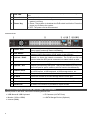
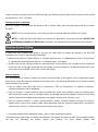
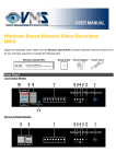
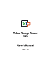
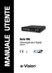
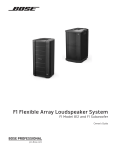
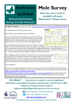
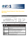
Windows Based Network Video Recorders NW-16/24 Package Content Inspect the packaging carton. Make sure the Windows Based NVR is properly delivered. Remove all items from the box and make sure the box contains the following items. Windows Based NVR Setup Guide SATA Cable Power Cord Front Panel 1 USB 3.0 Ports 2 USB 2.0 Ports 3 Camera LED 4 UpLink LED 5 WAN LED 6 HDD LED The USB 3.0 ports support all 3.0, 2.0 and 1.0 devices. Users can connect external USB devices, such as a USB mouse, a USB keyboard, a USB storage device, etc. The USB 2.0 ports allow users to connect external USB devices, such as a USB mouse, a USB keyboard, a USB storage device, etc. With different models of NVR, the number of Camera LED is also different. The following is description of the lightened LEDs. 1. Orange: The power is supplied by the camera itself. 2. Green: The power is supplied by the PoE switch at the rear panel. 1. Orange: Network speed is 10/100 Mbps. 2. Green: Network speed is 1000 Mbps. 1. Blink: The HDD/CF Card is running. 2. OFF: No storage device is found. 7 PoE LED 8 Reset Switch 9 Power Key 000AA241Z100Rear The PoE LED will start to blink when the output power is reaching to the limit. Insert a pin to force restart the system. 1. Blue: The system is on. The power key will not respond while the system is running. 2. Green: They system is shutdown but PoE switch is still alive. Press the power key to startup the system. 3. OFF: The power cord is disconnected. Panel 1 Power Jack 2 PoE Switch 3 UpLink – RJ-45 4 RS232 5 UpLink – SFP 6 USB 2.0 Ports 7 WAN – RJ-45 Connect the power supply cord shipped with the NVR. Use of other power supply cords may cause overloading. The PoE switch provides connection to IP cameras. With different models of NVR, the number of PoE switch is also different. This is for connection to a router or switch within the NVR’s private network, to share the network connection. The RJ-45 port will not function when the SFP port is connected, no matter before or after. This port provides connection to a RS232 device. Users can connect a SFP module that expands the NVR’s private network connection by fiber ports. This port has absolute priority over the RJ-45 port for uplink, and they will not function simultaneously. The USB 2.0 ports allow users to connect external USB devices, such as a USB mouse, a USB keyboard, a USB storage device, etc. This port is for network connection to the internet. 8 e-SATA Users can connect an e-SATA storage device via this port. 9 HDMI Monitor A HDMI connector is provided for connection to a HDMI monitor. 10 VGA Monitor The VGA output connector is offered for connection to a VGA monitor. 11 Audio Out An audio out connector is provided to output sounds. Connect Required Devices and Power On the NVR Before power on the NVR, connect the following devices first. USB Mouse & USB Keyboard IP Cameras (via PoE Ports) Monitor (VGA or HDMI) e-SATA Storage Device (Optional) Internet (WAN) 2 Lastly, connect the power cord to the NVR and login the Windows system. Note that the power source should be between AC 110V ~ AC 240V. Startup the NVR on Standby When the system is shutdown but the power is still on (Green LED), users can press the power key to restart the NVR. NOTE: Due to security concern, the Power key will not respond while the Windows is running. NOTE: If USB hub and KVM switch are required for application, insert these devices AFTER THE SYSTEM SUCCESSFULLY BOOTS UP. Otherwise, the unknown devices may cause boot-up failure. Windows System Setting Internet Information Server (IIS) If users have any software that needs to use port 80, users have to change the setting of IIS and VSS connection port. Refer to the following instructions. Switch ON the IIS via <Control Panel> <System and Security> <Administrative Tools> <Services> <World Wide Web Publishing Service> <Startup type> <Enable>. At VSS, click on the <Setting> button of VSS and select <Client Setting> tab. Change the port number at <Connect Port> at top-right. Note that the port number must be changed to a different number that is not often used, such as 20000. Click <OK> to save the setting. Restore System It is recommended to create a restore point when users first start up the system. Once unexpected system errors occur, users can restore the system to the restore point. The following describes how to create a restore point and restore the system. Click on <Start> menu and right click on <Computer>. Click on <Properties> <System Protection>. <System Properties> will be displayed. Click on <Create…> button below to setup a restore point. Users will be asked to name the restore point. After users input a name, click on <Create> button. A message window will indicate a restore point is being created. Users will be notified that the setting is completed, and can click <Close> to exit. Click on <System Restore…> under “System Restore” section. <System Restore> will pop out. Click on <Next> button, and a list of restore points will be displayed. Select a preferred restore point, and click on <Next> button. Click on <Finish> button to start restoring the system. A warning window will be displayed. Select <Yes> to start restoring the system. This process may take a while, so please wait patiently. The system will reboot by itself. An information window will pop out, indicating the system restore has finished. For more details, please visit 3 http://windows.microsoft.com/en-US/windows7/products/features/system-restore Turn Off Windows Updates To prevent the NVR from stopping recording due to automatic system restart after Windows updates, it is recommended to turn off Windows Updates. Follow the steps to disable this function. Go to <Control Panel> <System and Security> <Windows Update> <Change Settings>. Select <Never check for updates (not recommended) > under “Important updates” section. Uncheck the selections under “Recommended updates” section, and “Who can install updates” section. Then, click <OK> to save the settings and exit. After the above setting is done, click on <Start> menu, right click on <Computer>, and then select <Manage>. Select <Service> under <Services and Applications> on the left. Double click on <Windows Update>. Select <Disabled> next to “Startup type:”, and click <Stop> under “Service Status” section. Click < OK > to apply the setting and exit. Conditionally Turn On Windows Updates If users wish to update Windows system, follow the steps below to enable this function. Go to <Control Panel> <System and Security> <Windows Update> <Change Settings>. Select <Install updates automatically (recommended) > under “Important updates” section. Click <OK> to save the settings and exit. Automatic Windows Updates will begin. NOTE: After Windows is updated, users MUST turn off Windows Updates by following the same steps in “Turn Off Windows Updates” section. Local Display NVR vs. Non-Local Display NVR For NVR with CPU supporting local display, Video Storage Server (VSS) and Video Management Solution (VMS) are pre-installed. Startup the NVR system and VSS & VMS will automatically startup as well. For NVR requiring Live video display at a different PC, only Video Storage Server (VSS) will be pre-installed. Startup the NVR system and VSS will automatically startup as well. The following sections with VMS contents do not apply to the non-local display NVR. Users can install and operate VMS at a different PC according to the User’s Manual of VMS. NOTE: If users turn on the Windows Firewall, please add VSS and VMS to the exception list of the Windows Firewall to avoid them from being block by the firewall. 4 NOTE: If users already have any familiar backend software other than VSS, please refer to the software’s manual for installation and operation. Auto Connection of VSS and VMS Refer to the following for details of auto connection and auto setting of VSS and VMS. VSS and VMS will be automatically login with the username “admin” and the password “1234”. IP cameras connected via the PoE ports are plug-and-play. They will be automatically added to the start group of VSS. The <Schedule Record> setting will be unavailable. VSS is preset to record all sites at all times. VMS will automatically add VSS as the start group and videos from the connected IP cameras will be automatically retrieved and displayed. Auto HDD Management The Auto HDD Management function of VSS helps to automatically add all connected HDDs, except the C drive, as the storage folders of the recorded videos. If the system has detected any portable HDD at any time, it will be added to the folder list as well. Click on the <Setting> button and select the <File Path> tab to see the folder list. Check the box in front of <Hard Disk Auto Detection> to enable or disable this function. NOTE: For 16CH models, WD RED and WD Se series HDDs are recommended. As for 24CH models, it is recommended to install WD RED, Se or Re series HDDs. Add More IP Camera Sites If any PoE port is not connected to IP cameras, users can add IP camera connections via internet. Follow the steps below. Click on the <Setting> button. Right click on <New Group> in the site tree and select <Add a site> to add another connected IP camera. Input the IP address of the IP camera or find it via <Device Search>. Input the username and password to complete adding the IP camera site. Alternatively, users can also right click on <New Group> in the site tree and select <Add sites…> to add multiple IP camera sites at once. Press and hold the “Ctrl” key to select IP cameras. Then input username and password for each site Enable auto streaming configuration for the added IP cameras. Click on <OK> at the bottom to save the setting. Default IP Addresses for IP Cameras and VSS The connected IP cameras will each be automatically assigned a unique IP address, for connection from other devices in the same local area network. The default IP address for CH1 is 192.168.50.11; for CH2 is 192.168.50.12; and so on. Note that the network setting of the IP cameras need to be set to DHCP or the NVR will not be able to assign the default IP addresses to them. 5 In the mean time, VSS also has a default IP for LAN connection, which is 192.168.50.27 for 16CH models and 192.168.50.35 for 24CH models. This IP address can be found when users check <Control Panel> <Network and Sharing Center> <Local Area Connection> <Details>. NOTE: The IP address of the VSS for WAN connection can be found via <Control Panel> <Network and Sharing Center> <Local Area Network 3> <Details>. NVR Remote and Mobile Apps Support Users can also connect to VSS via NVR Remote, the remote monitoring software, and/or Apps such as NetGuard / NetGuardHD (iOS) or DroidGuard / DroidGuardHD (Android) on portable handy devices. After VSS is connected, users can view both Live / Playback videos and can search the video database. Refer to the User’s Manual of VSS and the App’s Help info for detailed description. NSW - Silverwater VIC ACT Unit 4, 52 Holker Street Unit 3 / 1 Rocklea Drive 22 Isa Street Silverwater NSW 2128 Port Melbourne VIC 3207 Fyshwick ACT 2609 E: [email protected] E: [email protected] E: [email protected] P: +61 2 9395 1400 P: +61 3 9646 4166 P: +61 2 6162 4600| F: +61 2 9647 0014 F: +61 3 9646 4155 F: +61 2 6162 4605 NSW - Sydney City QLD WA Unit 10, 10 Bradford Street Unit 2/ 40 Borthwick Ave 28a Teddington Rd Alexandria NSW 2015 Murarrie QLD 4172 Burswood WA 6100 E: [email protected] E:[email protected] E: [email protected] P: +61 2 9304 4555 P: +61 7 3399 5280 P: +61 8 9361 7000 F: +61 2 9700 8055 F: +61 7 3399 9805 F: +61 8 9361 7011 6