1
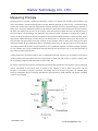
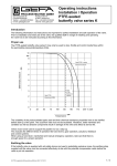
Darhor Technology CO., LTD.
Contents
1 Main features of D H 250 intelligent metal variable area flowmeter
2 Measuring principle of D H 250 intelligent metal variable area flowmeter
5 Technical parameter of D H 250 intelligent metal variable area flowmeter
6 Transducer type of D H 250 intelligent metal variable area flowmeter
8 Transducer material of D H 250 intelligent metal variable area flowmeter
8 Outline dimension of D H 250 intelligent metal variable area flowmeter
10 Indicator of D H 250 intelligent metal variable area flowmeter
11 Selection methods of D H 250 intelligent metal variable area flowmeter
16 Selection table of D H 250 intelligent metal variable area flowmeter
17 Electrical connection of D H 250 intelligent metal variable area flowmeter
23 Installation precaution of D H 250 intelligent metal variable area flowmeter
25 Customer maintenance of D H 250 intelligent metal variable area flowmeter
26 Operating instructions of D H 250 intelligent metal variable area flowmeter
32 Common fault and treatment of D H 250 intelligent metal variable area flowmeter
33 Appendix
www.darhor.com
E-mail:[email protected]
Darhor Technology CO., LTD.
Main Features
DH250 intelligent metal variable area flowmeter has local display type and intelligent remote type. Intelligent
remote type provides customers with very flexible options such as pointer display, LCD display for
instantaneous flowrate or total flow, standard two-wire 4~20mA current output, HART communication, etc.
Besides, the meter adopts advanced microprocessor and high quality industrial components to ensure superior
performance in various applications.
According to different installation pattern of measuring tube, when flow direction is from bottom to top, from
left to right or from right to left, different installation type can be selected as per the customer requirements.
Matching M6 indicator on the measuring tube will be the intelligent remote type. M6 indicator is the
multifunction digital magnetic measurement transmitter designed for DH250 intelligent metal variable area
flowmeter, which core is the MCU and adopts magnetic transducer to measure magnetic field change through
digital signal processing technology such as digital filtering, software amendment, etc. Two-line LCD display
provides a good interactive interface, and current signal output and Hart communication provide more
selections for customers.
z
z
z
z
z
z
z
z
z
Very suitable to small diameter and low velocity
Simple structure , reliable performance, low maintenance and long service life
Low requirements for straight pipe
Wide turndown ratio: 10:1
Local display type and intelligent remote type
Single-axis sensitive indicator
Non contact magnetic coupling system to ensure stable data transmission
Can be used in flammable and explosive dangerous situations
Protection grade: IP65
Main features of intelligent M6 indicator
z
z
z
z
z
z
z
z
Measure the angle displacement of magnetic field
LCD display for instantaneous flowrate or total flow alternately
Parameter setting can be realized
Data recovery function
HART Communication
Single-axis sensitive indicator
Backlight LCD display
Intrinsical safe type and flame proof type available
www.darhor.com
E-mail:[email protected]
1
Darhor Technology CO., LTD.
Measuring Principle
Detecting element of metal variable area flowmeter consists of a tapered tube extending from bottom to top
and a float inbuilt in tapered measuring tube vertically. Working principle is shown as Fig. 1: when fluid flows
upward into annular space between tapered tube and float, the float will move upward along the tube due to
lifting force formed by differential pressure of up and down end of float. When the flowrate of fluid increases,
the float will displace much more; on the contrary, when the flowrate of fluid decreases, the displacement of
float will reduce correspondingly, too. Therefore, the position of float is decided by the flowrate of fluid, as
well as the flowrate determines annular area between the maximum outside diameter of float and inner wall of
tapered tube. When fluid keeps a stable flowrate, the float locates in a dynamic balance state, the annular area
between float and tapered tube also keeps constant. At this moment, there are three forces acting on the float:
downward weight W, upward floating force F and fluid dynamic force P, and these forces locate in balance.
According to Bernoulli equation of hydrodynamics, force equilibrium equation and fluid continuity principle,
we can calculate the average instantaneous flowrate flowing into the annular area, so the float flowmeter is
also called variable area flowmeter.
A high-performance permanent magnet steel is embedded inside float. By this way, the magnetic field will be
produced around the float. When flowrate of fluid tends to stable and float locates in dynamic balance state,
the surrounding magnetic field distribution reaches stable, too.
By means of the flowrate indicator mechanically connected with tapered tube, the magnetic signal of the float
will be transmitted in non-contact form. In another word, indicator is able to detect and process with the
flowrate in the mode of magnetic transducer, and finally shows the flowrate by pointer on indicator scale
board, or intelligently process to display instantaneous and total flow in LCD indicator and outputs a standard
4-20mA current signal.
www.darhor.com
E-mail:[email protected]
2
Darhor Technology CO., LTD.
Measuring Principle
Basic formula of volumetric flowmeter Q is:
If the float is hollow body, Q is:
Thereinto: α-------flowrate factor, determined by float shape
ε-------gas expansion parameter; ε= 1 for liquid
△F----annular flowing area, m2
g-------local gravity acceleration, m/s2
Vf------float volume, m3
ρf-------density of float material, kg/m3
ρ--------density of measured fluid; for gas, density of gas upstream of float, kg/m3
Ff-----------cross-sectional area of float at maximum diameter, m2
Gf---------float weight, kg
The relationship between the annular area and lifting height of the float is shown as below, when structure
design is confirmed, d and β are constants. Formula contains quadratic term of h, usually, this nonlinear term
can not be neglected. Only when the tapered angle is little, it can be considered as linear approximately.
Thereinto: d-----------------Maximum diameter of the float, m
h-----------------Lifting height of float (starting from ID of tapered tube =Dmax of float), m
β-----------------Tapered angle of the tapered tube
a, b--------------Constant
www.darhor.com
E-mail:[email protected]
3
Darhor Technology CO., LTD.
Measuring Principle
According to process mode of measuring signal, metal variable area flowmeter can be divided into:
a. Local display: rotate follow-up magnet in the local indicator by the magnetic coupling with magnet inbuilt
in the float to drive the pointer to indicate the flowrate on scale directly (Fig. 2 as below).
b. Intelligent remote display: rotate follow-up magnet in the intelligent indicator by the magnetic coupling
with magnet inbuilt in the float to drive the sensing magnet and pointer, at the same time the change of the
magnetic field is converted to electrical signal by magnet transducer, and after process by A/D converter,
digital filter, microprocessor processing, D/A converter, to LCD display instantaneous and total flowrate (Fig.
3 as below).
www.darhor.com
E-mail:[email protected]
4
Darhor Technology CO., LTD.
Technical Parameter
z
Measuring range
Water (20℃) 10 ~ 300000 L/h
Air (20℃, 0.1013MPa) 0.7 ~ 3000 m3/h
Refer to flowrate table, special flowrate can be ordered.
z
Turndown ratio: 10:1 for standard
z
Accuracy: ±1.5% for local, ±1.0% for remote
z
Rated pressure: DN15 ~ DN50
4.0MPa (Max DN15: 32MPa, DN25: 25MPA, DN50: 20MPa)
DN80 ~ DN250 1.6MPa (Max DN80: 10MPa, DN100: 6.4MPa, DN125: 4.0MPa,
DN150: 4.0MPa, DN200: 2.5MPa, DN250: 2.5MPa)
z
Pressure loss: 1.5 ~ 60kPa
z
Viscosity:
DN15: <30mPa · s
DN25: <250mPa · s
DN50 ~ DN250: <300mPa · s
z
Fluid temperature: Local: -80 ~ +300℃
Remote: -40 ~ +150℃
z
High temperature: 350℃
Ambient temperature: Local: -40 ~ +80℃
Remote: -40 ~ +50℃
z
Storage temperature: -20 ~ +60℃
z
Relative humidity: ≤85%
z
Connection type: Standard: DIN2501
Special: specified by user
z
Protection grade: IP65
z
Remote type
Cable connector: M20*1.5
Power supply: 24VDC
Output signal: 4 ~ 20mA DC, HART
LCD display: Numerical range for instantaneous flowrate: 0 ~ 50000
Numerical range for total flow: 0 ~ 99999999
Explosion proof: Intrinsical safe: Exia IIC T6
Flameproof: Exd IIB T6
www.darhor.com
E-mail:[email protected]
5
Darhor Technology CO., LTD.
Transducer Type
Transducer is also named as measuring tube, consisting of tapered tube, float, guider, brake and mounting
flange.
Classified by pipe installing type:
Vertical installing type: FA (Fig. 4), FAP (Fig. 5), FAPV (Fig. 6)
Horizontal installing type: FD (Fig. 7), FDPV (Fig. 8)
Classified by corrosive characteristics of measured fluid:
Standard type: FA, FD
Corrosion resistant type: FAP, FAPV, FATi, FDPV
Classified by state of measured fluid:
Liquid: Common type
Gas: FAZ gas damping type (Fig. 9)
Classified by temperature of measured fluid:
High temperature: Cooling jacket FAT (Fig. 10), FDT (Fig. 11)
Low temperature: Heating jacket FAT, FDT
www.darhor.com
E-mail:[email protected]
6
Darhor Technology CO., LTD.
Transducer Type
www.darhor.com
E-mail:[email protected]
7
Darhor Technology CO., LTD.
Transducer Material
www.darhor.com
E-mail:[email protected]
8
Darhor Technology CO., LTD.
Outline Dimension
www.darhor.com
E-mail:[email protected]
9
Darhor Technology CO., LTD.
Indicator
There are two kinds of indicators: local indicator and remote one. Local indicator means displaying the
flowrate by means of mechanical pointer on site; for remote indicator, it can display on site and convert
flowrate signal into 4-20mA current signal, so as to control the flowing process of fluid by connecting with
control system.
Local display indicator
Common local indicator M8 (Fig. 13)
Punch forming of stainless steel and polishing the surface, mechanical pointer indicates flowrate on site.
Remote indicator
Remote indicator M6 with function of HART communication (Fig. 14)
Intrinsical safe & flameproof available, mechanical pointer indicates flowrate on site, LCD display mode is:
instantaneous flowrate, total flow with Hart communication function.
Note: Every kind of indicator can be freely combined with any transducer to be various flowmeters with
different specifications.
www.darhor.com
E-mail:[email protected]
10
Darhor Technology CO., LTD.
Selection Methods
1. Collection of process data
z
z
z
z
Ingredients, density and viscosity of measured fluid;
Maximum flowrate, minimum flowrate and normal flowrate;
Maximum operating pressure;
Maximum temperature and minimum temperature.
2. Maximum flowrate and minimum flowrate must conform to the flowrate range of Table 1 and
Table 2.
www.darhor.com
E-mail:[email protected]
11
Darhor Technology CO., LTD.
Selection Methods
www.darhor.com
E-mail:[email protected]
12
Darhor Technology CO., LTD.
3. DN calculation
DN calculation for liquid
Volumetric flowrate of measured liquid Qt (L/h)
Put density and maximum flowrate of measured liquid into Formula 1, and calculate the flowrate of
water—standard medium; then, find out the corresponding diameter and float number from flowrate table and
put the flowrate of water provided by standard float No. into Formula 1 again, accordingly, make out the
flowrate of measured liquid; finally, adjust the flowrate into an integer so that to get the scale range of
measured liquid.
Mass flowrate of measured liquid Qm (kg/h)
Calculation formula of scale range is as follows while calculation method is as above:
Thereinto:
Qt ------Max volumetric flowrate of measured liquid (L/h)
Qm -----Max mass flowrate of measured liquid (kg/h)
Qs ------Flowrate of standard medium water (L/h)
ρf-------Density of float (kg/m3)
ρt-------Density of measured liquid (kg/m3)
ρs-------Density of water (kg/m3)
Float density of various materials as follows:
Example
Some liquid to be measured, its operating density is 850 kg/m3 and max. flowrate is 2400 L/h, please calculate
its diameter, float No. and scale range.
Solution: density of float ρf = 7800 kg/m3, density of water ρs = 1000 kg/m3
Put ρf = 850 (kg/m3) and Qt = 2400 (L/h) into Formula 1 to get Qs = 2188.86 L/h
Then, look up the flowrate table and find out: DN25, float No. F26.3, Qs =2500
Put Qs into Formula 1 again to get Qt = 2741.23
Then adjust it into an integer, get the scale range of this fluid: 270 ~ 2700 L/h.
www.darhor.com
E-mail:[email protected]
13
Darhor Technology CO., LTD.
DN calculation for gas
Gas is easily affected by temperature and pressure and quite different from liquid. Therefore, at the time of
calculating flowrate, we do not only consider the density factor, but also take account of the influences from
temperature and pressure, so it is extremely important to provide correct temperature and pressure of gas to be
measured under operating condition.
Standard flowrate of measured gas QN (Nm3/h)
Operating flowrate of measured gas Qt (m3/h)
Mass flowrate of measured gas Qm(kg/h)
Thereinto:
QN-----Max. volumetric flowrate of gas under standard condition (Nm3/h)
Qt------Max. volumetric flowrate of gas under operating condition (m3/h)
Qm-----Max. mass flowrate of gas under operating condition (kg/h)
Qs -----Flowrate of standard medium air (m3/h)
ρs ------Density of air under standard condition (kg/m3)
ρst ------Density of gas under standard condition (kg/m3)
ρt -------Density of gas under operating condition (kg/m3)
Ps-------Absolute pressure of air under standard condition (0.1MPa)
Pt-------Absolute pressure of gas under operating condition (MPa)
Ts-------Absolute Temp. of air under standard condition (293.15K)
Tt--------Absolute Temp. of gas under operating condition (K)
www.darhor.com
E-mail:[email protected]
14
Darhor Technology CO., LTD.
Example
Some gas to be measured, oxygen, its average molecular weight: 32; process pressure: 0.4MPa (gauge
pressure), process temperature: 25℃, Max. flowrate: 35Nm3/h, please calculate its diameter, float No. and
scale range.
Solution: ρs = 1.204kg/m3, Ps = 0.1MPa, Ts = 293.15K
ρst = 1.331kg/m3, Pt = 0.5MPa, Tt = 298.15K, QN = 35Nm3/h
Put the acquired data into Formula 3 to get Qs = 16.60 m3/h
Look up flowrate table, find out: DN 15, Float No: F16.8, Qs = 18
Put Qs into Formula 3 again, make out QN = 37.96
Then adjust it into an integer and get scale range of measured fluid: 3.8 ~ 38 Nm3/h
www.darhor.com
E-mail:[email protected]
15
Darhor Technology CO., LTD.
Electrical Connection
1. Mainboard of flowmeter with Hart function (Fig. 15)
Brief introduction
Mainboard of flowmeter with Hart function is a new kind of digital flow transmitter with Hart communication
function. It can configure on site to display instantaneous or total flow on large screen of LCD.
Features
z
Configurate by hand-held communicator or configuration software of PC
z
4 ~ 20 mA output with HART protocol digital communication (two wires)
Communication meets HART protocol standard
z
z
HART communication does not affect 4 ~ 20mA analog output
z
Power supply of HART transmitter: 12 ~ 36 VDC
Damping: 0 ~ 32s adjustable
z
z
Ambient temperature: -20 ~ +70℃
Wiring
Open the front cover of indicator, a blue connecting terminal on top of the base (Fig. 16) can be seen, then
carry out wiring according to wiring marks on terminal.
Meter adjustment on site
Flowmeter mainboard has two kinds of function modes: data setting mode and current minitrimming mode.
Factory setting is data setting mode.
z
Data setting mode can set configuration data, flowmeter data and reset total flow into zero.
z
Current minitrimming mode can minitrim 4mA and 20mA current.
17
www.darhor.com
E-mail:[email protected]
Darhor Technology CO., LTD.
Electrical Connection
Connection between meter and safety barrier
2. K1, K2 limit alarm switch
Brief introduction
K1, K2 limit alarm switch is installed in the M6 indicator. K1 is lower limit, K2 is upper limit, alarm point can
be set at will. K1, K2 alarm switch consists of two parts. One part is in the indicator and simply named KG22
which is composed of SJ3.5N transducer and cutting disc on the rotation axis (Fig. 17) and can set alarm point
within the entire flow range at will and indicate on the dial by the positioning pointer. The other part is
external isolated switching amplifier WE77/ Ex (Fig. 18: transistor relay).
WE77/ Ex is divided into WE77/ Ex-1 and WE77/ Ex-2. WE77/ Ex-1 (or WE77/ Ex-1-G) is only applicable to
one KG22 and acts on K1 or K2; WE77/ Ex-2 (or WE77/ Ex-2-G) is applicable to two KG22 and acts on K1
and K2.
18
www.darhor.com
E-mail:[email protected]
Darhor Technology CO., LTD.
Electrical Connection
KG22 technical data
WE77 technical data
19
www.darhor.com
E-mail:[email protected]
Darhor Technology CO., LTD.
Electrical Connection
Adjustment of WE77/ Ex-1 & WE77/ Ex-2
Isolated switching amplifier includes power supply, transistor rectifier amplifier and output middle relay.
WE77/ Ex-1 with a safety control circuit. WE77/ Ex-2 with two safety control circuit and its output is
equipped with wiring terminal of open circuit. It is also easy to change wiring to become closed circuit
operation or closed circuit operation with open circuit monitoring.
According to the following table, replace cable jumper to get various working condition. Indicate “relay
closure” with one LED.
Circuit connection of KG22 with isolated switcher WE77/ Ex
20
www.darhor.com
E-mail:[email protected]
Darhor Technology CO., LTD.
Electrical Connection
Wiring diagram of KG22 with WE77/ Ex-1
21
www.darhor.com
E-mail:[email protected]
Darhor Technology CO., LTD.
Electrical Connection
Wiring diagram of KG22 with WE77/ Ex-2
Installation and outline dimensional drawing
22
www.darhor.com
E-mail:[email protected]
Darhor Technology CO., LTD.
Installation
Precaution
meter
Installation Precaution
To ensure meter operation performance and measuring accuracy, please pay attention to:
z
The size of upstream and downstream pipe should be the same as meter size. Connecting flange or screw
thread should also match with that of meter. The upstream straight pipe (h1) must be five times nominal
diameter of meter. The downstream straight pipe is not less than 250mm;
z
For vertical installation, fluids flow from bottom to top and verticality keeps less than 2º; for horizontal
installation, the level angle should be less than 2º;
When install flowmeter on process pipeline, bypass pipe should be installed to handle with malfunction
z
conveniently or not to affect production during flushing;
z
To ensure meter accuracy, more than 5D straight pipe should be at upstream and 250mm straight pipe at
downstream;
z
Require to equip magnetic filter if ferromagnetic material contained in fluids;
Require to equip filter between valve and straight pipe once solid impurity exists in measured medium;
z
For gas measurement, pipe pressure should be not less than 5 times pressure loss of meter to ensure float
z
working stably;
z
When the fluid temperature is high over 220℃ or so low as easy to crystallize, it needs to take measures
of thermal insulation protection; jacket type should be applied for heating or cooling;
z
It is necessary that all standards of the pipe flange, fastener, sealing gasket should conform to the standard
of meter flange to ensure meter operation normally;
z
Generally speaking, the metal variable area flowmeter do not require maintenance after normal operation.
Some meter defects always happened during commissioning due to some dirty material in the pipe to
cause float be blocked, and the pointer of indicator is stopped fixedly. At this time, first close the valves
on both sides of the flowmeter, then disassemble the upper flange of the flowmeter, move out the float to
clean and then reassemble. Please notice that the flange nuts should be tightened up evenly and hold the
gasket;
z
The flange on the process pipeline must be coaxial and parallel to the flange of the meter. To avoid the
pipe vibration, suggest supporting the pipe. Control valve should be installed at the downstream of the
flowmeter;
Because the meter transmits signal by magnetic coupling, in order to ensure the meter performance,
z
ferromagnetic matter should not exist around the meter 10m at least;
z
Gas meter is calibrated under specified pressure. If the gas at the meter outlet is discharged into
atmosphere directly, it would produce pressure loss at the float, and cause the data distortion. Therefore,
require to install an exhausting valve at the meter outlet under this condition;
For flowmeter with LCD display, ensure to avoid sun shining indicator directly during installation, or
z
would reduce life of LCD.
z
Pay attention to install meter with PTFE liner. PTFE will be distorted under uneven pressure, so flange
nuts should not be tightened unevenly to avoid damaging PTFE liner.
Table of Max. torque as below:
23
www.darhor.com
E-mail:[email protected]
Darhor Technology CO., LTD.
Installation Precaution
Meter Installation Drawing
24
www.darhor.com
E-mail:[email protected]
Darhor Technology CO., LTD.
Customer Maintenance
z
z
z
z
z
z
z
z
Because the meter belongs to precise instrument, should handle with care during meter transportation,
installation, storage and usage, and avoid overstress in installation; meanwhile, not change the relative
position of indicator and transducer to ensure the meter accuracy;
There will be ferromagnetic particles deposited on the float in operating; if impurity is too much, it will
block float deadly or affect measuring accuracy. Therefore, please clean pipe and float regularly. If
necessary, mount magnetic filter at the meter inlet and clean it regularly;
Due to inside of indicator is electronic components, during disassembly the cover of housing, must
tighten the screws of the cover and seal the housing to prevent harmful materials such as liquid
ferromagnetic or corrosive gas from entering the meter. At the same time, ensure housing grounded
reliably;
When use the meter first time, should notice the following two points:
Liquid measurement: open valve slowly to avoid water head attacking the meter;
Gas measurement: before running, do not exert pressure on pipe, or if valve is opened suddenly, float
would rush to brake to damage meter. Therefore, open valve slowly. Recommend a damping device to be
equipped to reduce float vibration at utmost.
For intelligent remote indicator, first, ensure correct wiring, check up and then power on meter. Otherwise,
easy to damage meter. Key operation must conform to the manual. If operate blindly, it will cause data
stored in EEPROM lost or damaged;
Meter should be stored in the place with temperature -20℃ ~ +60℃, relative humidity ≤85%, no
sunshine and corrosive gas;
When open housing of explosion proof flowmeter to maintain on site, should turn off the power;
When ambient temperature is lower than -30℃ or higher than 85℃, LCD may appears stasis or blind
screen, however, LCD won’t damage under this condition; when temperature reverts to normal range,
LCD display normally.
25
www.darhor.com
E-mail:[email protected]
Darhor Technology CO., LTD.
Operating Instructions
Keyboard Instruction
Normally, double-key is for flowmeter operating model, K2S key and K1Z key all located on PCB, and need
to open cover of LCD indicator to see.
K2S key (which is short for S key hereinafter)
In operating mode, press S key for 3s to enter looking through configuration parameter mode and press S
key to see about every parameter.
In password input mode, press S key to enter parameter setting menu tree; on submenu set parameter
z
revision state, it is setting parameter key, which also is data storage key on submenu set parameter
storage state.
K1Z key (which is short for Z key hereinafter)
In operating mode, press Z key for 3s to entering password setting mode;
z
In setting mode, it is cursor moving key;
z
z
In looking through configuration parameter mode, press Z key to return operating mode.
Data storage way
In data setting mode, after data setting, press S key when down arrow is twinkling to realize data storage
function.
Setting of span, decimal point
Span and decimal point are set once out of factory, also can use S, Z key to reset.
Setting procedure is as follow:
Press S key to enter data setting mode, meanwhile, sign bit become twinkling, it means that can amend
z
sign bit.
z
To press S key again can switch over positive & negative of data (plus is shown as up arrow)
z
Press Z key, the first digit can be amended when it becomes twinkling, at this moment, press S key for a
long time or for several times, setting data circulates from 0 ~ 9.
z
Press Z key again, can set second to fifth digit by turns; setting method is the same as the setting for first
digit.
After setting the fifth digit, press Z key to set decimal point. Decimal point can be set when the four
z
decimal points become twinkling at the same time, press S key now, decimal point will switch over
circularly.
z
After decimal point setting, press Z key, it can be stored once left down arrow becomes twinkling.
z
Press S key, store setting; press Z key, sign bit becomes twinkling, it means that can reset parameter.
z
26
www.darhor.com
E-mail:[email protected]
Darhor Technology CO., LTD.
Operating Instructions
meter
Operating Instructions
Operating State
When flowmeter is operating, it displays instantaneous flowrate, total flow by turns.
If total flow is more than 99998, it displays as × 1000, right of LCD displays as “× 1000”
Zero Clearing Operation of Total Flow
Operation content
In operating mode, enter password input mode, input password 00001 to enter total flow clearing mode, and
select total flow clearing, after this to return operating mode.
Operation method
In operating mode, press Z to enter password input mode, combining Z key (cursor moving) with S key (data
setting), input password 00001, press Z key to move cursor to down arrow of left screen, which down arrow is
twinkling. Press S key to enter total flow clearing mode, press S key to select data of right down screen as
YES (YES is for clearing, NO is for not clearing). Press Z key to carry out total flow clearing and return to
operating mode.
Operation interface process
27
www.darhor.com
E-mail:[email protected]
Darhor Technology CO., LTD.
Operating
Instructions
meter
Operating
Instructions
Process for Adjusting Zero of the Instantaneous Flowrate
Parameter Setting
Operation content
Submenus belonging to parameter setting tree are: instantaneous flowrate unit setting, lower limit of span
setting, high limit of span setting, damping time, lower limit alarm setting, high limit alarm setting, media state
selection, density setting, float density setting etc.
28
www.darhor.com
E-mail:[email protected]
Darhor Technology CO., LTD.
Operating
Instructions
meter
Operating
Instructions
Operation method
In operating mode, press Z to enter password input mode, combining Z key (cursor moving) with S key (data
setting), input password 00002, press Z key to move cursor to down arrow of left screen, which down arrow is
twinkling. Press S key to enter the first item in parameter setting mode (instantaneous flowrate unit selection
submenu), Press Z key to enter next submenu (lower limit of span setting), then, with the same method to enter
next submenu. Operation for every content is shown as following operation interface process.
Enter parameter setting operation interface process
29
www.darhor.com
E-mail:[email protected]
Darhor Technology CO., LTD.
Operating
Instructions
meter
Operating
Instructions
Example for parameter setting
Set L/H as instantaneous flowrate unit, operation process is shown as below:
30
www.darhor.com
E-mail:[email protected]
Darhor Technology CO., LTD.
Operating
Instructions
meter
Operating Instructions
Set 2.0000kg/m3 as liquid density, operation procedure is shown as below:
Looking Through Setting Parameter
In operating mode, press S key for 3s to look through setting parameter quickly, looking through sequence is
the same as parameter setting operation interface process.
Corresponding Relationship between Instantaneous Flowrate Unit and Total Flow Unit:
31
www.darhor.com
E-mail:[email protected]
Darhor Technology CO., LTD.
Operating Instructions
owmeter Common Fault & Treatment
32
www.darhor.com
E-mail:[email protected]
Darhor Technology CO., LTD.
Appendix 1 Relationship Between Velocity and Flowrate
Appendix 2 Manufacture Standard of Metal Variable Area Flowmeter
GB/T
JJG
GB/T
6844-93
257-94
15464-1995
Metal Variable Area Flowmeter
Verification Regulations of Rotameter
General Technical Specifications of Instruments Packing
33
www.darhor.com
E-mail:[email protected]