1
M910 / M910E
User’s manual
Electromagnetic flowmeter
MEATEST
1
Electromagnetic flowmeter M910 / M910E
Basic information ___________________________________________________7
1.1
1.2
1.3
2
Basic features __________________________________________________________ 7
Standards and approvals _________________________________________________ 7
Warranty ______________________________________________________________ 8
Preparing for start up ________________________________________________9
2.1
2.2
2.3
2.4
3
Inspecting contents of the package _________________________________________ 9
Fuse replacement _______________________________________________________ 9
Power supply__________________________________________________________ 10
Power supply voltage selection (M910E, 115/230V version only) ________________ 10
Installation _______________________________________________________11
3.1
3.2
Sensor location ________________________________________________________ 11
Electrical connection ___________________________________________________ 15
3.2.1
3.2.2
3.3
3.4
4
Power supply ____________________________________________________________ 15
Electric connection between converter and sensor – Remote version ______________ 16
Sensor grounding ______________________________________________________ 17
Turning the display panel _______________________________________________ 17
Electronic unit description ___________________________________________18
4.1
4.2
4.3
Front panel (display) ___________________________________________________ 18
Rear panel (inputs/outputs) ______________________________________________ 19
Signal terminals _______________________________________________________ 20
4.3.1
4.3.2
4.3.3
4.3.4
4.3.5
4.3.6
4.4
5
Current loop output_______________________________________________________ 20
Frequency output_________________________________________________________ 21
Impulse output ___________________________________________________________ 21
Status output (M910 only)__________________________________________________ 22
PLC digital input (M910 only) ______________________________________________ 22
Serial port RS485 (M910 only)______________________________________________ 23
Serial port RS232 ______________________________________________________ 24
Operation _________________________________________________________25
5.1
Main menu ___________________________________________________________ 25
5.1.1
5.1.2
5.1.3
5.1.4
5.1.5
5.1.6
5.1.7
5.1.8
5.1.9
5.2
Current Flowrate / Total Volume ___________________________________________ 25
Positive Volume __________________________________________________________ 25
Negative Volume _________________________________________________________ 25
Auxiliary Volume_________________________________________________________ 25
Maximum Flowrate / Maximum Flowrate Time (M910 only)_____________________ 25
Maximum Flowrate (M910E only)___________________________________________ 25
Minimum Flowrate / Minimum Flowrate Time (M910 only) _____________________ 26
Minimum Flowrate (M910E only) ___________________________________________ 26
Datalogger (M910 only) ___________________________________________________ 26
Setup menu ___________________________________________________________ 26
5.2.1
Input and outputs configuration (1 INPUT/OUTPUT) __________________________ 27
5.2.1.1 Current loop output (1.1 CURRENT) _______________________________________ 27
5.2.1.2 Frequency output (1.2 OUTPUT F) _________________________________________ 27
5.2.1.3 Impulse output (1.3 OUTPUT P) ___________________________________________ 28
5.2.1.4 Pulse width (1.4 PULSE WIDTH) __________________________________________ 30
5.2.1.5 Status output (1.5 OUTPUT S) (M910 only) __________________________________ 30
5.2.1.6 PLC digital input (1.6 INPUT) (M910 only) __________________________________ 31
5.2.1.7 Low flowrate limit (1.7 LIMIT PF1) ________________________________________ 31
5.2.1.8 High flowrate limit (1.8 LIMIT PF2)________________________________________ 32
5.2.1.9 Hysteresis of flowrate limits (1.9 HYSTERESIS) ______________________________ 32
5.2.1.10 RS485 baud rate (1.A RS485 B.R.) (M910 only) ______________________________ 32
Operation manual
3
Electromagnetic Flowmeter M910 / M910E
MEATEST
5.2.1.11 RS485 address (1.B RS485 ADDR.) (M910 only) _____________________________
5.2.2
Flowmeter configuration (2 FLOWMETER) _________________________________
5.2.2.1 Flowrate units (2.1 FLOW UNIT) _________________________________________
5.2.2.2 Flowrate resolution (2.2 FLOW RESOL.) ___________________________________
5.2.2.3 Volume units (2.3 VOLUME UNIT) _______________________________________
5.2.2.4 Volume resolution (2.4 VOL. RESOL.) _____________________________________
5.2.2.5 Flowrate direction (2.5 FLOW DIREC.) ____________________________________
5.2.2.6 Low-flow cutoff (2.6 L.F.CUTOFF) ________________________________________
5.2.2.7 Moving average time constant (2.7 TIMECONST) ____________________________
5.2.2.8 Time setting (2.8 TIME SET.) (M910 only) __________________________________
5.2.2.9 Date setting (2.9 DATE SET.) (M910 only) __________________________________
5.2.2.10 Datalogger setting (2.A DATALOGGER) (M910 only) _________________________
5.2.3
General settings (3 GENERAL) ____________________________________________
5.2.3.1 Diameter (3.1 DIAMETER) ______________________________________________
5.2.3.2 Nominal flowrate range QN (3.2 RANGE) ___________________________________
5.2.3.3 Serial number (3.3 SERIAL NR.)__________________________________________
5.2.3.4 Power supply (3.4 POWER SUP.) _________________________________________
5.2.3.5 Self-test (3.5 SELFTEST)________________________________________________
5.2.3.6 Current Loop Test (3.6 C.LOOP TEST)_____________________________________
5.2.3.7 Basic Menu Password (3.7 PASSWORD MN.) _______________________________
5.2.4
Calibration menu (4 CALIBRATION) ______________________________________
5.2.4.1 Number of Calibration Points (4.1 NR.OF CALP.) ____________________________
5.2.4.2 Calibration point 1 (4.2 CAL.POINT 1) _____________________________________
5.2.4.3 Calibration point 2 (4.3 CAL.POINT 2) _____________________________________
5.2.4.4 Calibration point 3 (4.4 CAL.POINT 3) _____________________________________
5.2.4.5 Calibration point 4 (4.5 CAL.POINT 4) _____________________________________
5.2.4.6 Calibration Password (4.6 PASSWORD CA.) ________________________________
6
32
32
33
33
33
34
34
34
35
35
35
35
35
36
36
36
36
36
36
36
37
37
37
38
38
38
38
System control ____________________________________________________ 40
6.1
6.2
6.3
6.4
7
8
RS485 bus properties (M910 only)_________________________________________40
RS232 bus properties ___________________________________________________40
Command syntax_______________________________________________________40
Command list _________________________________________________________41
Error messages ___________________________________________________ 54
Maintenance _____________________________________________________ 55
8.1
8.2
8.3
9
Advice for correct operation ______________________________________________55
Periodical maintenance _________________________________________________55
What to do in case of failure _____________________________________________55
Application information ____________________________________________ 57
9.1
Weight and dimensions__________________________________________________57
9.1.1
9.1.2
9.1.3
9.2
9.3
Electronic unit – compact version___________________________________________ 57
Electronic unit – remote version ____________________________________________ 57
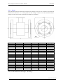
Sensor _________________________________________________________________ 58
Used materials_________________________________________________________59
Flowrate versus diameter ________________________________________________60
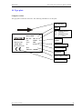
10 Type plate________________________________________________________ 61
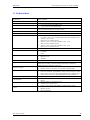
11 Technical data ____________________________________________________ 63
12 Ordering information - options ______________________________________ 64
12.1 Example of order_______________________________________________________64
13 Terminology______________________________________________________ 65
Appendix A Measuring principle _______________________________________ 66
4
Operation manual
MEATEST
Electromagnetic flowmeter M910 / M910E
Appendix B M910 Menu structure (M910 only) ____________________________67
Appendix C M910 Material selection _____________________________________71
Operation manual
5
Electromagnetic Flowmeter M910 / M910E
6
MEATEST
Operation manual
MEATEST
1
1.1
Electromagnetic flowmeter M910 / M910E
Basic information
Basic features
The inductive flow meter M-910 is designed to measure, indicate and record the instantaneous and total
flow of the conductive media flowing through the sensor. The flow meter M-910 records both forward and
reverse flows. As there are no moving parts in the flow profile the M-910 can be used to measure
extremely dirty liquids containing solids. The only limitation is that the flowmeter can be used solely with
conductive liquids.
Range of applications. The inductive flow meter M-910 is for use in the Chemical Industry, Paper
Industry, Water and Wastewater Treatment Industry and most other process industries.
Features. The inductive flowmeter M-910 is a highly accurate and stable device. The construction of the
M-910 flowmeter uses components with long-term, time and temperature stability. Configuration data is
backed up and can be recovered after a power failure. The back-up structure enables data recovery even if
a partial loss of data occurs as a result of (e.g. high level electrostatic discharge or a noisy power supply).
Internal CPU provides all functions usually built in electronic flow meters, incl. low flow rate correction,
frequency response setting, bandwidth of sensitivity setting at low flow rates, etc.
Outputs. Flowmeter M-910 is equipped with 6 standard isolated outputs: 4 to 20mA either active or
passive, frequency output, impulse output, status (relays) output, RS485 and RS232 output. User can
configure these outputs. Status and RS485 outputs are not available for M910E.
Power supply. Both versions of the standard 115V/230V power supply and 24V DC/AC power supply are
available.
1.2
Standards and approvals
Electromagnetic flowmeter is conformed to requirements for bearing CE mark.
Electromagnetic flowmeter electronic unit, both remote and compact version meet safety requirements
according to standard EN 61010-1 including amendment A2.
Electromagnetic flowmeter electronic unit, both remote and compact version meets EMC
requirements according to standard EN 61000-3, EN 61000-4, EN 61000-6
Pipe with sensor meets requirements of Pressure Equipment Directive 97/23/EC.
Both the pipe and electronic unit, meet the requirements of degree of protection provided by enclosure
level IP67, according to EN 60529 (IEC 529).
Operation manual
7
Electromagnetic Flowmeter M910 / M910E
1.3
MEATEST
Warranty
Within the manufacturers general supply conditions, all material and manufacturing faults are covered by
that. It is up to us whether the warranty obligation includes a repair free of charge or corresponding
replacement. Place of the warranty obligation is Czech Republic. Further claims on compensation,
especially for loss of production or resultant of damages, are strictly excluded.
Any defects caused by improper use are absolutely not included in the warranty. Excluded from warranty
are also expendable items (as i.e. accumulators, batteries, pushbuttons after attained life time, ribbons,
etc.)
In case of a warranty claim the user is asked to give detailed description of the defect and also of the
application for which you use the product. This information is important in order to avoid time and cost
extensive tests and for the eventual achievement of warranty claims from our suppliers and sub-suppliers.
For the item or instrument, returned after the expired warranty time, repair or replacement on warranty
can only be accepted, if manufacturer has been informed in time that a warranty case has occurred.
Warranty period for all types of electromagnetic flowmeter is 24 months.
The flowmeter should only be used according to the
instructions described in this operating manual.
8
Operation manual
MEATEST
2
Electromagnetic flowmeter M910 / M910E
Preparing for start up
2.1
Inspecting contents of the package
Basic package includes the following items:
Flanged sensor
Electronic Transmitter (can be integral or remote)
Spare fuse
Operating manual.
Calibration certificate
Special wrench for opening the housing covers
Magnet for control without opening the housing
Software Flow910
RS232 cable
The flowmeter is delivered ready for use after connecting to the power supply. Please check that it has
been correctly installed according to chapter “Installation”.
Only a power supply with the appropriate voltage and frequency should be used. The flowmeter can be
supplied with either 230/115V 50/60Hz, or 24V (12V, 48V) DC/AC power supply, see ordering
information in chapter “Power supply”.
2.2
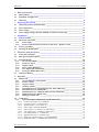
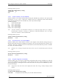
Fuse replacement
A mains fuse is located behind the back cover. The fuse must only be exchanged by a competent person.
Procedure is as follows:
Disconnect the power supply from the flowmeter.
Unscrew the back cover using the special wrench (standard part of delivery).
The fuse holder is located behind the back cover. Remove the fuse. Replace it with new fuse with the
same rating.
Screw on the back cover.
Fuse holder
Reconnect the power supply.
Note:
Operation manual
9
Electromagnetic Flowmeter M910 / M910E
T315mA fuse is used for 115/230 V version
1A fuse is used for 24 and 48 V DC/AC versions
2A fuse is used for 12 V DC
2.3
MEATEST
Power supply
From a power supply point of view the flowmeter is delivered in four basic versions:
115/230V ( +10%, -15%), 50/60Hz, automatic switching for M910 (manual switching for M910E)
12V DC (+20%, -10%)
24V DC (+20%, -10%), 24V 50/60Hz (+10%, -10%)
48V DC (+20%, -10%), 48V 50/60Hz (+10%, -10%)
2.4
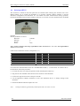
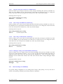
Power supply voltage selection (M910E, 115/230V version only)
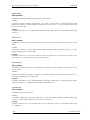
M910E is equipped with a power supply voltage selector, which enables the use of both 115VAC and
230VAC supply voltage. The selector is located on the PC board (see below). It is accessible after
removing the cover as follows:
Disconnect the power supply from the flowmeter.
Unscrew the back cover using the special wrench (standard part of delivery).
The power supply voltage selector is located behind the back cover. Move the jumper to the required
position.
Screw on the back cover.
Reconnect the power supply.
Power supply voltage selector
Note: M910 is equipped with automatic power supply selector.
10
Operation manual
MEATEST
3
3.1
Electromagnetic flowmeter M910 / M910E
Installation
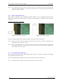
Sensor location
To avoid measuring errors due to gas/air entrainment or to a partly filled pipe, please observe the
following:
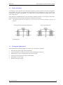
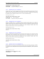
Horizontal (standard) mounting
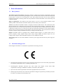
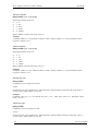
The sensor tube must always remain full. The best way to achieve this is to locate the sensor in a low
section of pipe, see the following picture. It is recommended to install the sensor in a section of straight
pipe with at least 5 times the pipe diameter before sensor and 3 times after sensor.
5 DN
3 DN
3 DN
5 DN
Pipe reducers
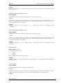
If the pipe diameter is not the same as the diameter of sensor, then pipe reducers can be used. So as not to
lose accuracy of the measurement, the slope of reducers should not exceed 8.
Operation manual
11
Electromagnetic Flowmeter M910 / M910E
MEATEST
8
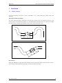
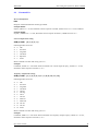
Vertical mounting
When the sensor is mounted on a vertical section of pipe, the flow direction must be upwards. In the case
of a downward flow direction, air bubbles can collect in the sensor and the measurement could be unstable
and inaccurate.
Pumps
Never install the sensor on the suction side of a pump or on a section of pipe where a vacuum is possible.
12
Operation manual
MEATEST
Electromagnetic flowmeter M910 / M910E
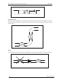
Valves
Suitable location of a shutoff valve is downstream of a sensor.
Removal during maintenance
If the application requires removal of the sensor for periodic maintenance, it is recommended to install a
bypass section as the following drawing.
Position of electrodes
The axis of measuring electrodes must be approximately horizontal (see picture).
YES
Operation manual
NO
13
Electromagnetic Flowmeter M910 / M910E
MEATEST
Vibration
To avoid mechanical damage protect both electronic unit and sensor against mechanical vibrations. When
strong vibrations are possible, both the input and output pipe must be mechanically fixed or the remote
version with a separate electronic unit should be used.
Overheating
To avoid overheating, the electronic unit should be protected against direct sunlight especially in areas
with a warm climate with ambient temperatures over 30 oC. If necessary a sunshade has to be mounted
over the electronic unit or a remote version with a separate electronic unit should be used.
14
Operation manual
MEATEST
3.2
Electromagnetic flowmeter M910 / M910E
Electrical connection
Only a competent person may connect the flowmeter to the mains power supply.
The flowmeter can be connected to the power supply with either a fixed power cable or with a flying lead
cable and plug. Cable entries on the electronic unit can be used for flexible electrical cables. Cables with a
diameter between 8 and 10 mm must be used to keep protection IP67. It is not recommended to use rigid
metal or plastic conduits.
If you use a cable and plug it is recommended that the cable has a cross-section of 3 x 1.5mm2 and with a
minimum length of 1 m.
In the case of a fixed connection an independent power switch or circuit breaker should be located close to
the flowmeter. Cable cross-section as above.
3.2.1
Power supply
To connect the compact version to the power supply the following procedure should be used.
Unscrew the back cover using the special wrench (standard part of delivery).
Connect the earth wire (yellow-green colour) to the central grounding point inside the case. The end
of earth wire must be hooked (app. 3 mm) and fixed to the earth screw.
Connect Live and Neutral power cables to the power line terminal clamps with labels 14 (L-wire,
brown terminal colour) and 13 (N-wire, blue terminal colour).
Screw on the back cover.
Switch on the power supply.
GND central grounding point
L line wire
N line wire
Note:
Be careful to avoid following problems during electrical installation:
Do not cross or loop cables inside electronic unit.
Use separate cable entries for power supply and signal wires.
Operation manual
15
Electromagnetic Flowmeter M910 / M910E
3.2.2
MEATEST
Electric connection between converter and sensor – Remote version
For remote version converter and flanged sensor are connected with two (2-wire unshielded and 3-wire
shielded) cables. Standard length of cables is 6 meter. It is recommended to mount the transmitter not too
far from the flanged sensor. Use cables as short as possible.
Five-terminal connector i s located in separated box. The
same box is used for the converter and also for the sensor.
Colours of wires are following:
3-wire shielded
wire):
Blue (Brown):
Green :
Red (White):
2-wire cable:
Brown :
White :
cable (shielding is connected to the green
Electrode 1 (EL1)
Ground
Electrode 2 (EL2)
Excitation 1 (EXCITATION)
Excitation 2 (EXCITATION)
Following procedure should be observed to connect sensor cable to the
transmitter or sensor:
Switch off power supply.
Dismount top cover of connection box. Four screws must be removed.
Connect 5 wires to the connector.
As the basic protection of connection box is IP65 it is important (in case
you need better protection) to fill the box (with connected wires) with
reenterable insulating and sealing compound. One piece of compound is
standard part of delivery. Using this technology will be protection of
transmitter IP67 and protection of sensor IP68.
Mount the cover back.
Switch on power supply.
16
Operation manual
MEATEST
3.3
Electromagnetic flowmeter M910 / M910E
Sensor grounding
To ensure the correct operation of the flowmeter an earthing connection between the sensor and pipeline
must be made. The sensor is equipped with screw connection for an earthing wire. This screw has to be
connected to the flange on the pipeline. Use Copper wire to connect between the flange and the earth
screw on the sensor.
If the pipeline is manufactured from a non-electrically conductive material, or if the pipe is lined with a
similar material, special grounding rings must be installed between flanges.
Note:
The flowmeter must not be switched on, if the sensor is not connected /earthed to the rest of
pipeline!
Sensor grounding without grounding rings
Sensor grounding with
grounding rings
3.4
Turning the display panel
The flowmeter M910 (M910E) display can rotated ± 90°. Procedure is as follows:
Disconnect the power supply from the flowmeter.
Unscrew the back cover using the special wrench (standard part of delivery).
Detach the two screws in the front plate and remove the plate.
Unscrew next two legs and carefully turn the display.
Reassemble in reverse order.
Reconnect the power supply.
Operation manual
17
Electromagnetic Flowmeter M910 / M910E
4
MEATEST
Electronic unit description
4.1
Front panel (display)
4
1
2
3
1
RS232 connector
RS232 port enables you to connect the flowmeter to a personal computer. Serial port is galvanically
isolated from other electronic circuits.
2
Display
Two-row alphanumerical display is used for displaying all information. The instantaneous flowrate is
displayed in upper row. Total volume is displayed in the lower row.
The decimal point position and type of units can be changed in the flowmeter “Setup Menu” (see chapter
“Flowmeter configuration”).
3
Keyboard (M910 only)
4 keys enable you to change flowmeter configuration and provide flowmeter calibration. These are “UP”,
“DOWN”, “ESC” and “ENTER” keys.
18
Operation manual
MEATEST
4
Electromagnetic flowmeter M910 / M910E
Magnetic sensor
All important displayed information can be read
without opening the flowmeter. The sensor
display can be activated by using a magnet.
Activating the sensor (less than 3 seconds)
using a magnet is equal to pushing the “UP”
key. Activating
the sensor (more than 3
seconds) is equal to pushing “RIGHT” key.
4.2
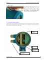
Rear panel (inputs/outputs)
Under the back cover of the electronic unit are the terminals for input/output signals and supply terminals.
The fuse holder is located near the power supply terminals. The top cable gland is for input/output signals
cable, bottom cable gland for power supply cable.
Signal
terminals
Fuse
Power supply
terminals
Cable glands
Operation manual
19
Electromagnetic Flowmeter M910 / M910E
4.3
MEATEST
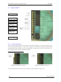
Signal terminals
Current loop
Frequency output
Impulse output
Status output
(M910 only)
PLC input
(M910 only)
RS485 interface
(M910 only)
Power supply
4.3.1
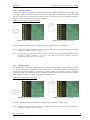
Current loop output
The 4 to 20 mA current loop can be set as a passive type between outputs 1, 2 (1 positive, 2 negative) or as
an active type between outputs 2, 3 (2 positive, 3 negative). In both cases the outputs are galvanically
isolated from all other electronic circuits of the flowmeter. Voltage drop on passive current loop is 4 V.
Active current loop can work to a maximum of 800 .
Example of current output connection:
Passive current output connection
Active current output connection
For more information about current output see chapter “Input and outputs configuration”.
20
Operation manual
MEATEST
4.3.2
Electromagnetic flowmeter M910 / M910E
Frequency output
The frequency output is a galvanically isolated transistor NPN switch. Voltage drop on the switch is 1 V
in the made status. Maximum switched voltage is 50 V. Maximum switched current should not exceed
100 mA. Positive output is on terminal 4, negative output is on terminals 5 and 7 (internally connected).
Frequency range of the output is from 10 Hz to 12 kHz.
Example of the frequency output connection:
Passive frequency output connection
Active frequency output connection
For more information about frequency output see chapter “Input and outputs configuration”.
Note 1: Frequency, impulse and status outputs are galvanically connected to each other and galvanically
isolated from other electronic circuits.
Note 2: Active frequency output uses the power supply of the current output. Total current take-off from
this power supply (terminal nr. 1) must be less than 40 mA. Active frequency output is
galvanically connected to current output.
4.3.3
Impulse output
The impulse output is formed by a galvanically isolated transistor NPN switch. Voltage drop on the switch
is 1 V in the made mode. Maximum switched voltage is 50 V. Maximum switched current should not
exceed 100 mA. Positive output is on terminal 6, negative output is on terminals 5 and 7 (internally
connected). Width of the impulse can be set. Maximum frequency of impulse output is limited by impulse
width. Maximum frequency is 50 Hz for the shortest impulse 10 ms
Example of impulse output connection:
Passive impulse output connection
Active impulse output connection
For more information about impulse output see chapter “Input and outputs configuration”.
Note 1: Frequency, impulse and status outputs are galvanically connected to each other and galvanically
isolated from other electronic circuits.
Operation manual
21
Electromagnetic Flowmeter M910 / M910E
MEATEST
Note 2: Active impulse output uses the power supply of the current output. Total current take-off from
this power supply (terminal nr. 1) must be less than 40 mA. Active impulse output is galvanically
connected to current output.
4.3.4
Status output (M910 only)
Status output is formed by relays. Maximum switched voltage is 100 V. Maximum switched current
should not exceed 500 mA. First output is on terminal 8, second output is on terminal 5 and 7 (internally
connected).
Example of status output connection:
Passive status output connection
Active status output connection
For more information about status output see chapter “Input and outputs configuration”.
Note 1: Frequency, impulse and status outputs are galvanically connected to each other and galvanically
isolated from other electronic circuits.
Note 2: Active status output uses the power supply of the current output. Total current take-off from this
power supply (terminal nr. 1) must be less than 40 mA. Active status output is galvanically
connected to the current output.
4.3.5
PLC digital input (M910 only)
The digital input is activated with a DC voltage between 5 and 30 V (positive or negative). The digital
input is between terminals 9 and 10.
For more information about digital input see chapter “Input and outputs configuration”.
Note:
22
PLC digital input is galvanically isolated from other electronic circuits.
Operation manual
MEATEST
4.3.6
Electromagnetic flowmeter M910 / M910E
Serial port RS485 (M910 only)
The serial port RS485 is assigned for online communication between flowmeter and computer. It is
suitable for real time flowmeter monitoring. In contrast to the RS232 serial port, which is suitable for oneshot configuration or calibration of the flowmeter. The RS485 can be connected to up to 16 flowmeters
together and the total connection length of all wires can be up to 800 meters. Positive output (A) is on
terminal 11, negative output (B) on terminal 12.
Example of three flowmeters and one computer interconnection:
All flowmeters and computer are connected parallel using twisted pair cable. At each end of the
communications line should be 470 terminations.
910 _ 1
910 _ 2
910 _ 3
PC
470
470
Interconnection of three flowmeters and computer using RS485 bus
Flowmeters are marked with numbers. These numbers are equal to the flowmeters RS485 address.
Program Flow910 is designed for flowmeter control using RS485 or RS232 serial bus.
Note:
Communication through the serial port RS485 is a half duplex type. The flowmeter is a listener
and sends data only after a query from a computer. Each flowmeter has it’s own RS485 address.
The range of addresses is 0 to 255. Factory setting of RS485 address is 0. Communication speed
is selectable between 4800 and 19200 Bd. For cables over 100m or if there is a noisy power
supply voltage (especially peaks generated, usually by motors, etc.), select communication speed
below 9600 Bd.
Note:
Serial port RS485 is galvanically isolated from other electronic circuits.
Operation manual
23
Electromagnetic Flowmeter M910 / M910E
4.4
MEATEST
Serial port RS232
The connector is located on the front panel and is accessible after removing the electronic unit cover.
RS232 enables you to connect the flowmeter to a personal computer. RS232 interface is used for
flowmeter configuration and calibration. It’s not suitable for online communication during operation,
because the flowmeter must be open and IP67 protection is not valid. For such communication use RS485
interface.
RS-232 parameters are fixed:
Baud rate
Data bits
Stop bit
Parity
1200 Bd
8
1
none
Note: Control computer must keep signal RTS in static level between –3 to –12 V and signal DTR in
static level +3 to +12V
Cable between Flowmeter and PC (configuration 1:1)
PC
Receiver
Transmitter
DTR (+3 … +12V) static level
Ground
RTS (-3 … -12V) static level
D-Sub 1
2
3
4
5
7
D-Sub 2
2
3
4
5
7
Flowmeter
Transmitter
Receiver
Power supply RS232 +
Ground
Power supply RS232 -
For connection of the flowmeter to the PC a standard RS232 cable (1 : 1) can be used. To connect a PC to
the flowmeter, follow this procedure:
Unscrew the front cover using the special wrench (standard part of delivery).
Plug the one end of the RS cable onto the serial connector in the flowmeter.
Connect the opposite end to the serial port in the PC.
Use the application software (Flow910) to enter new calibration data or to change settings of the
flowmeter.
Disconnect RS232 cable and replace the cover.
Note:
24
Serial port RS232 is galvanically isolated from other electronic circuits.
Operation manual
MEATEST
5
Electromagnetic flowmeter M910 / M910E
Operation
5.1
Main menu
The flowmeter is in Main menu after the switching power on or after repeatedly pushing the ESC key.
This entire menu can be operated with a magnetic without opening the housing. Short use of the magnet
(less than 3 seconds) is equal to pushing “UP” key. Longer use of the magnet (more than 3 seconds) is
equal to pushing “RIGHT” key.
The following information can be displayed in the Main Menu.
Note: M910E can be operated by a magnetic pointer only.
5.1.1
Current Flowrate / Total Volume
Basic display (after power on). Current flowrate is
displayed on the first line. Total volume is displayed on the
second line. Flow in the forward direction is added to this
volume, Flow in the reverse direction i s subtracted.
Measuring parameters (units, resolution, moving average etc.) are selectable in Setup menu. After
pushing “UP” key “Positive Volume” is displayed.
5.1.2
Positive Volume
Total volumetric flow in a forward direction. After pushing
“UP” key “Negative Volume” is displayed.
5.1.3
Negative Volume
Total volumetric flow in the reverse direction. After
pushing “UP” key “Auxiliary Volume” is displayed.
5.1.4
Auxiliary Volume
Second Total Volume counter. Can be cleared by pushing
“RIGHT” key. It is usually used for measuring volumetric
flow during a set period such as day, month etc.. After
pushing “UP” key “Maximum Flowrate” is displayed.
5.1.5
Maximum Flowrate / Maximum Flowrate Time (M910 only)
Maximum flowrate value indicated since last reset (pushing
“RIGHT” key). Date and time of maximum flowrate is
displayed in lower row. After pushing “UP” key “Minimum
Flowrate” is displayed.
5.1.6
Maximum Flowrate (M910E only)
Maximum flowrate value indicated since last reset (longer
use of the magnet).
Operation manual
25
Electromagnetic Flowmeter M910 / M910E
5.1.7
MEATEST
Minimum Flowrate / Minimum Flowrate Time (M910 only)
Minimum flowrate value indicated since last reset (pushing
“RIGHT” key). Date and time of minimum flowrate is
displayed in lower row. After pushing “UP” key
“Datalogger” is displayed.
5.1.8
Minimum Flowrate (M910E only)
Minimum flowrate value indicated since last reset (longer
use of the magnet).
5.1.9
Datalogger (M910 only)
Number of samples stored in datalogger and percentage
used. Individual samples value can be read after pushing
“RIGHT” key. In this submenu samples are read
s
e
q
u
e
ntially. Next sample (Flowrate with Date and Time) is displayed after pushing “UP” key.
“Sequential reading” submenu is left after pushing “RIGHT” key or after displaying all values.
After pushing “UP” key “Current Flowrate / Total Volume” is displayed. Datalogger capacity is
more than 10000 samples (typical 15000 samples).
These formats are changed pushing key “UP” or by short activating of the magnet.
5.2
Setup menu
Note: For version M910E is the “Setup menu” accessible only using the computer and software
Flow910.
In this menu the flowmeter parameters (measuring, output, communication etc.) can be changed. Access
to the Setup menu is enabled after pushing the “ENTER” key from the Main menu.
Note:
The keyboard is accessible after unscrewing the cover of the electronic unit using the special
wrench, which is standard part of delivery.
Correct password must be entered before entering Setup menu. Without correct password the access to the
Setup menu is refused. Default factory set password is “00000”. Return to the Main menu is possible after
pushing the “ESC” key.
26
Operation manual
MEATEST
Electromagnetic flowmeter M910 / M910E
Setup menu has the following structure (items are changed by pushing “UP” key and selected by pushing
“ENTER” key):
Setup Menu structure
5.2.1
Input and outputs configuration (1 INPUT/OUTPUT)
For the flowmeter outputs and input configuration. After pushing “UP” key next item (“2
FLOWMETER“) is selected. After pushing “ENTER” key following submenu is displayed:
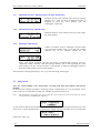
5.2.1.1
Current loop output (1.1 CURRENT)
Current loop 4 to 20 mA can be set as passive type between outputs 1, 2 (1 positive, 2 negative) or as
active type between outputs 2, 3 (2 positive, 3 negative). In both cases outputs are galvanically separated
from all other electronic circuits of the flowmeter. Voltage drop on the passive current loop is 4 V. Active
current loop can work to a maximum of 800 .
Current loop output can be programmed in one of the following modes:
a)
Off
b) Pos.Flow
c)
Neg.Flow
d) Abs.Flow
e)
Bip.Flow
f)
Fixed
current output is adjusted to 4mA (error message 01 - “Current output”
is switched off)
current 4+16*Flowrate / QI [mA] is generated for a positive flowrate
direction. For a negative flowrate direction 4mA is generated.
current 4-16*Flowrate / QI [mA] is generated for a positive flowrate
direction. For a positive flowrate direction 4 mA is generated.
current 4+16*abs(Flowrate) / QI [mA] is generated for both flowrate
directions.
current 12+8*Flowrate / QI [mA] is generated for both flowrate
directions.
current output is adjusted to fixed value (4.000 … 20.000 mA)
QI value represents a flowrate for a current of 20 mA and can be set independently to the nominal
diameter of the sensor. QI value can be changed in “Setup mode” after selecting modes “b”, “c”, “d” or
“e”. Fixed current value can be changed in “Setup mode” after selecting mode “f”. Following values are
pre-set:
Current loop standard factory setting:
Mode „Positive flowrate“.
QI
flowrate corresponds to maximum required nominal flowrate QN
5.2.1.2
Frequency output (1.2 OUTPUT F)
Frequency output is a galvanically isolated transistor NPN switch. Voltage drop on the switch is 1 V in the
made status. Maximum switched voltage is 50 V. Maximum switched current should not exceed 100 mA.
Positive output is on terminal 4, negative output is on terminals 5 and 7 (internally connected). Frequency
range of the output is from 10 Hz to 12 kHz.
The frequency output can be programmed in one of following modes:
a) Off
b) Pos.Flow
c)
Neg.Flow
d) Abs.Flow
Operation manual
output is not active (off state).
frequency 1000*Flowrate/QF [Hz] is generated for positive flowrate
direction.
frequency -1000*Flowrate/QF [Hz] is generated for negative flowrate
direction.
frequency 1000*abs(Flowrate)/QF [Hz] is generated for both flowrate
directions.
27
Electromagnetic Flowmeter M910 / M910E
e) On Pos.
f) On Neg.
g) On In
h) On Out
i)
j)
k)
l)
m)
Dose On
Dose Off
On<F2
On>F2
Fixed
MEATEST
output is off in case of negative flow and made in case of positive flow.
output is off in case of positive flow and made in case of negative flow.
output is on, when flowrate is higher than PF1 and lower than PF2,
otherwise it is off.
output is off, when flowrate is higher than PF1 and lower than PF2,
otherwise it is on.
output is on, when programmed dose is counting, otherwise it is off.
output is off, when programmed dose is counting, otherwise it is on.
output is on, when flowrate is lower than PF2, otherwise it is off.
output is on, when flowrate is higher than PF2, otherwise it is off.
frequency output is adjusted to fixed value (10 … 12000 Hz)
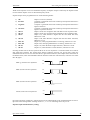
If setting the flow limit is chosen, hysteresis H can be set too. Hysteresis is a tolerance field on one
side of flow limits PF1 and PF2. The output status changes (indicates crossing over the pre-set limit),
when the immediate flowrate crosses over the value PF2 (or goes below limit PF1). The output status
comes back to the default status, when the immediate flowrate decreases under the value PF2-H (or
increases over limit PF1+H) again.
OFF
Mode g ) with non-zero hysteresis:
ON
Mode h) with non-zero hysteresis:
PF1 PF1+H
PF2-H PF2
PF1 PF1+H
PF2-H PF2
OFF
ON
OFF
Mode k) with non-zero hysteresis:
ON
PF2-H PF2
Mode l) with non-zero hysteresis:
OFF
ON
PF2-H PF2
QF value represents flowrate for frequency 1000 Hz and can be set independently to the nominal diameter
of the sensor. QF value can be changed after selecting modes “b”, “c” or “d”. Fixed frequency value can be
changed after selecting mode “m”. Following values are pre-set:
Frequency output standard factory setting:
Mode
QF
PF1
PF2
H
„Positive flowrate“.
flowrate corresponds to the required nominal flowrate QN
limit corresponds to the required nominal flowrate -QN
limit corresponds to the required nominal flowrate QN
hysteresis corresponds to the required nominal flowrate QN/10
Parameters PF1, PF2 and H are common for frequency, impulse and status mode.
5.2.1.3
Impulse output (1.3 OUTPUT P)
Impulse output is formed by a galvanically isolated transistor NPN switch. Voltage drop on the switch is 1
V in the made mode. Maximum switched voltage is 50 V. Maximum switched current should not exceed
100 mA. Positive output is on terminal 6, negative output is on terminal 5 and 7 (internally connected).
28
Operation manual
MEATEST
Electromagnetic flowmeter M910 / M910E
Width of the impulse can be set. Maximum frequency of impulse output is limited by the impulse width.
For the shortest impulse 10 ms is maximal frequency 50 Hz.
Impulse output can be programmed in one of the following modes:
a) Off
b) Pos.Flow
c)
Neg.Flow
d) Abs.Flow
e) On Pos
f) On Neg
g) On In
h) On Out
i)
j)
k)
l)
Dose On
Dose Off
On>F1
On<F1
output is not active (off state).
1 impulse is generated when total volume QP of liquid has flowed in a
positive direction.
1 impulse is generated when total volume QP of liquid has flowed in a
negative direction.
1 impulse is generated when total volume QP of liquid has flowed in a
negative or positive direction.
output is off in case of negative flow and made in case of positive flow.
output is off in case of positive flow and made in case of negative flow.
output is on, when flowrate is higher than PF1 and lower than PF2,
otherwise it is off.
output is off, when flowrate is higher than PF1 and lower than PF2,
otherwise it is on.
output is on, when programmed dose is counting, otherwise it is off.
output is off, when programmed dose is counting, otherwise it is on.
output is on, when flowrate is higher than PF1, otherwise it is off.
output is on, when flowrate is lower than PF1, otherwise it is off.
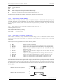
If setting of flow limit is chosen, hysteresis H can be set too. Hysteresis is a tolerance field on one side of
flow limits PF1 and PF2. The output status changes (indicates crossing over pre-set limit), when the
immediate flowrate crosses over the value PF2 (or goes below limit PF1). The output status comes back to
the default status, when the immediate flowrate decreases under the value PF2-H (or increases over limit
PF1+H) again.
OFF
Mode g ) with non-zero hysteresis:
ON
Mode h) with non-zero hysteresis:
PF1 PF1+H
PF2-H PF2
PF1 PF1+H
PF2-H PF2
OFF
ON
OFF
Mode k) with non-zero hysteresis:
ON
PF1 PF1+H
Mode l) with non-zero hysteresis:
OFF
ON
PF1 PF1+H
QP value represents volume for 1 impulse and can be set independently to the nominal diameter of sensor.
QP value can be changed after selecting modes “b”, “c” or “d”. Following values are pre-set:
Impulse output standard factory setting:
Operation manual
29
Electromagnetic Flowmeter M910 / M910E
Mode
QP
PF1
PF2
H
MEATEST
„Positive flowrate“.
1 m3
limit corresponds to the required nominal flowrate -QN
limit corresponds to the required nominal flowrate QN
hysteresis corresponds to the required nominal flowrate QN/10
Parameters PF1, PF2 and H are common for frequency, impulse and status mode.
5.2.1.4
Pulse width (1.4 PULSE WIDTH)
Function enables to change the pulse width of “Impulse Output” in milliseconds after pressing key
“ENTER”. With keys “UP” and “RIGHT” any value between 10 millisecond and 2500 milliseconds can be
set. To change the currently valid value to the new value press the key “ENTER”. Key “ESC” discards
changes.
Note:
Pulse width can be set with 10 ms resolution (values 10, 20, 30, …).
Following values are pre-set:
Pulse width standard factory setting:
Pulse width
100 milliseconds
5.2.1.5
Status output (1.5 OUTPUT S) (M910 only)
Status output is formed by relays. Maximum switched voltage is 100 V. Maximum switched current
should not exceed 500 mA. First output is on terminal 8, second output is on terminals 5 and 7 (internally
connected).
Status output can be programmed in one of the following modes:
a)
b)
c)
d)
Off
On Pos.
On Neg.
On In
e)
On Out
f)
g)
h)
i)
Dose On
Dose Off
On>F1
On<F1
output is not active (off state).
output is off in case of negative flow and made in case of positive flow.
output is off in case of positive flow and made in case of negative flow.
output is on, when flowrate is higher than PF1 and lower than PF2,
otherwise it is off.
output is off, when flowrate is higher than PF1 and lower than PF2,
otherwise it is on.
output is on, when programmed dose is counting, otherwise it is off.
output is off, when programmed dose is counting, otherwise it is on.
output is on, when flowrate is higher than PF1, otherwise it is off.
output is on, when flowrate is lower than PF1, otherwise it is off.
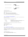
If setting of flow limit is chosen, hysteresis H can be set too. Hysteresis is a tolerance field on one side of
flow limits PF1 and PF2. The output status changes (indicates crossing over pre-set limit), when the
immediate flowrate crosses over the value PF2 (or goes below limit PF1). The output status comes back to
the default status, when the immediate flowrate decreases under the value PF2-H (or increases over limit
PF1+H) again.
OFF
Mode d) with non-zero hysteresis:
ON
Mode e) with non-zero hysteresis:
PF1 PF1+H
PF2-H PF2
PF1 PF1+H
PF2-H PF2
OFF
ON
30
Operation manual
MEATEST
Electromagnetic flowmeter M910 / M910E
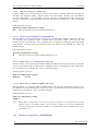
OFF
Mode h) with non-zero hysteresis:
ON
PF1 PF1+H
Mode i) with non-zero hysteresis:
OFF
ON
PF1 PF1+H
Following values are pre-set:
Status output standard factory setting:
Mode
PF1
PF2
H
„Off “.
limit corresponds to the required nominal flowrate -QN
limit corresponds to the required nominal flowrate QN
hysteresis corresponds to the required nominal flowrate QN/10
Parameters PF1, PF2 and H are common for frequency, impulse and status mode.
5.2.1.6
PLC digital input (1.6 INPUT) (M910 only)
Digital input is activated with DC voltage between 5 and 30 V (positive or negative). Digital input is
between terminals 9 and 10.
Digital input can be programmed in one of the following modes:
a) Off
b) Dose
c)
Clr.Vol
input is not active.
input activation starts dose QD measuring. Dosing indication can be
performed by one of outputs (frequency, impulse or status).
input activation clears the Auxiliary volume.
QD value represents volume for dosing. QD value can be changed after selecting mode “b”.
Following values are pre-set:
Digital input standard factory setting:
QD
volume 1 m3
Mode „Off“.
5.2.1.7
Low flowrate limit (1.7 LIMIT PF1)
Function enables you to set low flowrate limit for some functions of digital outputs after pressing
“ENTER” key. See “Frequency output”, “Impulse output” and “Status output”. With the “UP” and
“RIGHT” keys any value between +/- QMAX flowrate can be set. Limit PF1 is displayed in the same format
as the flowrate. To change the current valid value to the new value press the “ENTER” key. “ESC” key
discards changes.
Following values are pre-set:
Low flowrate limit standard factory setting:
PF1
limit corresponds to the required nominal flowrate -QN
Operation manual
31
Electromagnetic Flowmeter M910 / M910E
5.2.1.8
MEATEST
High flowrate limit (1.8 LIMIT PF2)
Function enables you to set high flowrate limit for some functions of digital outputs after pressing key
“ENTER”. See “Frequency output”, “Impulse output” and “Status output”. With the “UP” and “RIGHT”
keys any value between +/- QMAX flowrate can be set. Limit PF2 is displayed in the same format as the
flowrate. To change the current valid value to the new value press the “ENTER” key. “ESC” key discards
changes.
Following values are pre-set:
High flowrate limit standard factory setting:
PF2
limit corresponds to the required nominal flowrate QN
5.2.1.9
Hysteresis of flowrate limits (1.9 HYSTERESIS)
Function enables you to set hysteresis of limit values for some functions of digital outputs after pressing
key “ENTER”. See “Frequency output”, “Impulse output” and “Status output”. With the “UP” and
“RIGHT” keys any value between +/- QMAX flowrate can be set. Hysteresis is displayed in the same format
as the flowrate. To change the current valid value to the new value press the “ENTER” key. “ESC” key
discards changes.
Following values are pre-set:
Hysteresis standard factory setting:
H
limit corresponds to the required nominal flowrate QN/10
5.2.1.10
RS485 baud rate (1.A RS485 B.R.) (M910 only)
Function enables you to set parameter baud rate of RS485 interface after pressing “ENTER” key. With the
“UP” key any value from the row 4800, 9600 or 19200 Bd can be set. To change the current valid value to
the new value press the “ENTER” key. “ESC” key discards changes.
Following values are pre-set:
Baud rate standard factory setting:
Baud Rate
9600 Bd.
5.2.1.11
RS485 address (1.B RS485 ADDR.) (M910 only)
Function enables to set parameter address of RS485 interface after pressing “ENTER” key. With the “UP”
and “RIGHT” keys any value between 0 and 255 can be set. To change the current valid value to the new
value press the “ENTER” key. “ESC” key discards changes.
Following values are pre-set:
Baud rate standard factory setting:
ADDR 00.
Note:
RS485 address is important in case of connecting more flowmeters to common RS485 bus. Each
flowmeter has its own RS485 address. The connected computer can control communication
between these flowmeters using theirs addresses. Communication will be excluded in case of two
equal addresses.
5.2.2
Flowmeter configuration (2 FLOWMETER)
32
Operation manual
MEATEST
Electromagnetic flowmeter M910 / M910E
For flowmeter parameters configuration. After pushing “UP” key next item (“3 GENERAL“) is selected.
After pushing “ENTER” key following submenu is displayed:
5.2.2.1
Flowrate units (2.1 FLOW UNIT)
Function enables you to set flowrate units after pressing the “ENTER” key. With the “UP” key any item
from the list “l/s”, “m3/h”, “G/m” and “user” can be set. To change the current valid unit to the selected
unit press the “ENTER” key. “ESC” key discards changes.
Available units:
l/s
litres per second
m3/h cubic metres per hour
G/m
US gallons per minute
user
user-defined unit, factory-set is „l/h“ (litres per hour), user defined unit can be changed by
computer only
Following values are pre-set:
Flowrate units standard factory setting:
Flowrate units m3/h
User
l/h
5.2.2.2
Flowrate resolution (2.2 FLOW RESOL.)
Function enables you to set flowrate resolution after pressing the “ENTER” key. With the “UP” key any
item from the list “0”, “0.0”, “0.00”, “0.000” and “0.0000” can be set. To change the current valid
resolution to the selected resolution press the “ENTER” key. “ESC” key discards changes.
Available resolution:
0
without decimal digits
0.0
max. 1 decimal digit
0.00
max. 2 decimal digits
0.000 max. 3 decimal digits
0.0000 max. 4 decimal digits
Note:
selected resolution is the maximal resolution. It is reduced for high values. For example 4
decimal digits resolution is valid up to -99.9999 or 99.9999 displayed value. For higher values,
the resolution reduced (999.999).
Following values are pre-set:
Flowrate resolution standard factory setting:
Resolution
0.0000 for Q100% < 3.0000
0.000 for 3.000 Q100% < 30.000
0.00 for 30.00 Q100% < 300.00
0.0 for 300.0 Q100% < 3000.0
0 for Q100% 3000.0
5.2.2.3
Volume units (2.3 VOLUME UNIT)
Function enables to set volume units after pressing the “ENTER” key. With the “UP” key any item from
the list “m3”, “l”, “US.G” and “user” can be set. To change the current valid unit to the selected unit press
the “ENTER” key. “ESC” key discards changes.
Available units:
m3
cubic metres
l
litres
US.G US gallons
user
user-defined unit, factory-set is „l“ (litres), user defined unit can be changed by computer only
Operation manual
33
Electromagnetic Flowmeter M910 / M910E
MEATEST
Following values are pre-set:
Volume units standard factory setting:
Volume units
m3
User
l
5.2.2.4
Volume resolution (2.4 VOL. RESOL.)
Function enables to set volume resolution after pressing the “ENTER” key. With the “UP” key any item
from the list “0”, “0.0”, “0.00” , “0.000” and , “0.0000” can be set. To change the current valid resolution
to the selected resolution press the “ENTER” key. “ESC” key discards changes.
Available resolution:
0
without decimal digits
0.0
max. 1 decimal digit
0.00
max. 2 decimal digits
0.000 max. 3 decimal digits
0.0000 max. 4 decimal digits
Note:
selected resolution is the maximuml resolution. It is reduced for high values. For example 4
decimal digits resolution is valid up to -999.9999 or 9999.9999 displayed value. For higher
values the resolution is reduced (99999.999).
Following values are pre-set:
Volume resolution standard factory setting:
Resolution
0.000
5.2.2.5
Flowrate direction (2.5 FLOW DIREC.)
Function enables you to switch between “Positive” and “Negative” flow direction (change the sign in
flowrate value) after pressing the “ENTER” key. With the “UP” key any item from the list “Positive” and ,
“Negative” can be set. To change the current valid direction to the selected direction press the “ENTER”
key. “ESC” key discards changes.
Note:
flowmeters are working in both flow directions, however they are calibrated for positive direction
only.
Following values are pre-set:
Flowrate direction standard factory setting:
Flow direc.
Positive
5.2.2.6
Low-flow cutoff (2.6 L.F.CUTOFF)
Function enables you to set limit for suppressing low flowrates after pressing “ENTER” key. With the
“UP” key and “RIGHT” any value between +/- QMAX flowrate can be set. Limit is displayed in the same
format as the flowrate. To change the current valid value to the new value press the “ENTER” key. “ESC”
key discards changes.
Note:
All flowrates below this value will be displayed as 0.00. This setting is valid for display and all
outputs.
Following values are pre-set:
Low-flow cutoff standard factory setting:
L.F.Cutoff
corresponds to the flowrate Q1%/2 (see table 2 M910 Flowrates)
34
Operation manual
MEATEST
5.2.2.7
Electromagnetic flowmeter M910 / M910E
Moving average time constant (2.7 TIMECONST)
Function enables you to change the time for moving average calculating after pressing “ENTER” key.
With “UP” and “RIGHT” key any value between 1 second and 20 seconds can be set. To change the
current valid value to the new value press the “ENTER” key. “ESC” key discards changes.
Following values are pre-set:
Time constant standard factory setting:
Timeconst
10 seconds
5.2.2.8
Time setting (2.8 TIME SET.) (M910 only)
Function enables you to correct time of internal Real time clock after pressing “ENTER” key. With “UP”
and “RIGHT” key any time between 00:00:00 and 23:59:59 can be set. To change the current valid value
to the new value press the “ENTER” key. “ESC” key discards changes.
Following values are pre-set:
Time setting standard factory setting:
Time set.
Central European Time
5.2.2.9
Date setting (2.9 DATE SET.) (M910 only)
Function enables you to correct date of internal Real time clock after pressing key “ENTER” key. With
“UP” and “RIGHT” key any date between 01.01.2000 and 31.12.2099 can be set. To change the current
valid value to the new value press the “ENTER” key. “ESC” key discards changes.
Following values are pre-set:
Date setting standard factory setting:
Date set.
Actual date
5.2.2.10
Datalogger setting (2.A DATALOGGER) (M910 only)
Function enables you to set sample interval for internal datalogger after pressing “ENTER” key. With
“UP” key any value from the row OFF, 5, 10, 15, 30, 45, 60, 120, 180, 240 and CLR can be select. To
change the current valid value to the new value press the “ENTER” key. “ESC” key discards changes.
Datalogger will be cleared after selection item CLR. This selection doesn’t change datalogger sample
interval.
Following values are pre-set:
Datalogger standard factory setting:
Datalogger
OFF
5.2.3
General settings (3 GENERAL)
For general settings configuration or for reading actual settings. After pushing “UP” key next item is
selected. After pushing “ENTER” key following submenu is displayed:
Operation manual
35
Electromagnetic Flowmeter M910 / M910E
5.2.3.1
MEATEST
Diameter (3.1 DIAMETER)
Flowmeters nominal diameter is displayed. After pushing “UP” key “Range” is displayed.
5.2.3.2
Nominal flowrate range QN (3.2 RANGE)
Nominal flowrate range QN is displayed in flowrate units. After pushing “UP” key “Serial number” is
displayed.
5.2.3.3
Serial number (3.3 SERIAL NR.)
Flowmeters Serial number is displayed. After pushing “UP” key “Power supply” is displayed.
5.2.3.4
Power supply (3.4 POWER SUP.)
Information about power supply (voltage and frequency) is displayed. After pushing “UP” key “Self test”
is displayed.
5.2.3.5
Self-test (3.5 SELFTEST)
Function enables you to switch an internal self-test (flowrate simulator) “On” or “Off” after pressing
“ENTER” key. With “UP” key any item from the list “On” and, “Off” can be set. To change the current
valid self-test state press the “ENTER” key. “ESC” discards changes.
Note:
Self-test “Off” state is normal working state of flowmeter. After switching self-test to “On” state,
internal flowrate simulator is inserted instead of the pipe. Function can be used for signal
converter testing. Number in range (0.980, 1.020) is displayed, if signal converter is OK.
Number is displayed in state “On” only. After switching on you have to wait for converter
stabilization (up to 20 seconds).
Following values are pre-set:
Self-test standard factory setting:
Self-test
Off
5.2.3.6
Current Loop Test (3.6 C.LOOP TEST)
Function enables you to switch an internal test of the connected current loop “On” or “Off” after pressing
the “ENTER” key. With the “UP” key any item from the list “On” and, “Off” can be set. To change the
current valid Current Loop Test state press the “ENTER” key. “ESC” key discards changes.
Note:
If Current Loop Test is in “On” state and current output flows less than 3 mA, error message
“01 – Current Output” will be displayed.
Following values are pre-set:
Current Loop Test standard factory setting:
C.Loop Test
Off
5.2.3.7
Basic Menu Password (3.7 PASSWORD MN.)
Function enables you to enter a new password for basic menu access after pressing the “ENTER” key.
With the “UP” and “RIGHT” key any password in range between 00000 and 99999 can be set. To change
the current valid password to the new password press the “ENTER” key. “ESC” key discards changes.
36
Operation manual
MEATEST
Electromagnetic flowmeter M910 / M910E
Following values are pre-set:
Basic Menu Password standard factory setting:
PASSWORD MN.
00000
5.2.4
Calibration menu (4 CALIBRATION)
Setting any new value in calibration menu changes calibration data! Calibration
should be performed in an appropriate equipped laboratory.
We recommended using software Flow910 for easy Calibration. It contains
„calibration wizard“ and can prevent flowmeter from incorrect calibration.
Calibration menu is accessible as part 4 of the Setup menu, if the correct calibration password has been
entered. After entering the Basic menu password only parts 1 to 3 of Setup menu are accessible. Without
the correct password access to the Calibration menu is refused. Default factory set Calibration password
is “10000”.
Note:
5.2.4.1
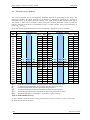
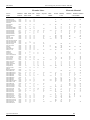
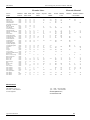
Flowmeter M910 enables calibration at 2, 3 or 4 points. Each calibration point contains 2
values. Nominal value of calibration point is selected by user in range between +/- QMAX (for
maximum flowrates see table 1: M910 flowrates). It is expressed in flowrate units. To this
nominal value is attached a calibration constant. Calibration constant doesn’t have a unit. In the
calibration process you change this calibration constant to reach similarity between standard
flowmeter and the calibrated flowmeter. Higher calibration constant means lower displayed
value.
Calibration constants must be different. In the case of two equal calibration constants, the
measured values could be wrong.
Number of Calibration Points (4.1 NR.OF CALP.)
Function enables you to enter a new number of calibration points after pressing the “ENTER” key. With
the “UP” and “RIGHT” keys any number in range between 2 and 4 can be set. To change the current valid
number to the new number press the “ENTER” key. “ESC” key discards changes.
Note:
Standard number of calibration points is 2. More calibration points are used for special
applications when higher accuracy is expected (negative flowrate, low flowrates etc.).
Following values are pre-set:
Number of Calibration Points standard factory setting:
NR.OF CALP. 2
5.2.4.2
Calibration point 1 (4.2 CAL.POINT 1)
Function enables you to change nominal and calibration value of Calibration point 1 after pressing the
“ENTER” key. With the “UP” and “RIGHT” keys any value in the range of real flowrates can be set. To
change the current valid nominal value to the new nominal value press the “ENTER” key. After entering
the nominal value a new calibration constant can be set. “ESC” key discards changes.
Following values are pre-set:
Operation manual
37
Electromagnetic Flowmeter M910 / M910E
MEATEST
Calibration point 1 standard factory setting:
Nominal point 5 … 10% of required QN
Cal. Constant is assigned according to the calibration
5.2.4.3
Calibration point 2 (4.3 CAL.POINT 2)
Function enables you to change the nominal and calibration value of Calibration point 2 after pressing the
“ENTER” key. With “UP” and “RIGHT” key any value in the range of real flowrates can be set. To
change the current valid nominal value to the new nominal value press the “ENTER” key. After entering
the nominal value new calibration constant can be set. “ESC” key discards changes.
Following values are pre-set:
Calibration point 2 standard factory setting:
Nominal point 40 … 70% of required QN
Cal. Constant is assigned according to the calibration
5.2.4.4
Calibration point 3 (4.4 CAL.POINT 3)
Function is available only if 3 or 4 calibration points are selected. Function enables you to change the
nominal and calibration value of Calibration point 3 after pressing the “ENTER” key. With the “UP” and
“RIGHT” key any value in the range of real flowrates can be set. To change the current valid nominal
value to the new nominal value press the “ENTER” key. After entering the nominal value a new
calibration constant can be set. “ESC” key discards changes.
Following values are pre-set:
Calibration point 3 standard factory setting:
Not used.
5.2.4.5
Calibration point 4 (4.5 CAL.POINT 4)
Function is available only if 4 calibration points are selected. Function enables you to change the nominal
and calibration value of Calibration point 4 after pressing the “ENTER” key. With the “UP” and
“RIGHT” keys any value in the range of real flowrates can be set. To change the current valid nominal
value to the new nominal value press the “ENTER” key. After entering the nominal value a new
calibration constant can be set. “ESC” key discards changes.
Following values are pre-set:
Calibration point 4 standard factory setting:
Not used.
5.2.4.6
Calibration Password (4.6 PASSWORD CA.)
Function enables you to enter a new password for calibration menu access after pressing the “ENTER”
key. With the “UP” and “RIGHT” keys any password in the range between 00000 and 99999 can be set.
To change the current valid password to the new password press the “ENTER” key. “ESC” key discards
changes.
Following values are pre-set:
Calibration Password standard factory setting:
PASSWORD CA.
10000
38
Operation manual
MEATEST
Operation manual
Electromagnetic flowmeter M910 / M910E
39
Electromagnetic Flowmeter M910 / M910E
6
MEATEST
System control
The flowmeter includes serial lines RS232 and RS485. RS232 connector is located behind the front panel.
RS485 terminals are behind the back panel. For the remote control to work properly, bus parameters must
be set in the setup menu. Address and baud rate are important for RS485 bus. Communication parameters
are fixed for RS232 bus.
6.1
RS485 bus properties (M910 only)
To transfer the data using RS485 bus, 8N1 data format is used, i.e. each data word includes 8 bits, no
parity and one stop bit. The communication speed can be set using the system menu. Available values:
4800, 9600 and 19200 Bd. Each flowmeter has it’s own RS485 address. Range of these addresses is from
0 to 255.
6.2
RS232 bus properties
To transfer the data using RS232 bus, 8N1 data format is used, i.e. each data word includes 8 bits, no
parity and one stop bit. Communication speed 1200 Bd is fixed.
6.3
Command syntax
Communication between flowmeter and computer consists of a flow of periodically alternating commands
type command-response or query-response. Command is always a text followed by parameter and ended
by control sign <cr>. Response is always ended with control sign <cr>.
Commands described in this chapter can be issued through both buses (RS485 and RS232). The only
difference is, that before all commands for RS485 bus is identification in form “#00”. Where ‘#’ is the
command prefix and “00” is flowmeters address 0 in hexadecimal form. For flowmeter with address 1 it’s
identification is “#01”. Flowmeter answers are prefix in form “>00” for flowmeter 0, “>01” for flowmeter
1 etc.
Syntax description
<DNPD> = Decimal Numeric Program Data, this format is used to express decimal number with or
without the exponent.
<CPD> =
Character Program Data. Usually, it represents a group of alternative character parameters.
e.g. {0 | 1 | 2 | 3}.
?=
A flag indicating a request for the value of the parameter specified by the command. No
other parameter than the question mark can be used.
(?) =
A flag indicating a request for the parameter specified by the command. This command
permits a value to be set as well as requested.
<cr> =
carriage return. ASCII code 13. This code executes the command or query.
40
Operation manual
MEATEST
6.4
Electromagnetic flowmeter M910 / M910E
Command list
Device identification
IDN?
Response contains flowmeters model type number.
Example RS232:
If query „IDN?<cr>” is sent, flowmeter returns response in format „M910-Vxxxx<cr>“ in case of M910.
Example RS485:
If query „#00IDN?<cr>” is sent, flowmeter returns response in format „>00M910-Vxxxx<cr>“.
Current output mode setting
SCM(?)<CPD> { 0 | 1 | 2 | 3 | 4 }
Following modes can be set:
0
1
2
3
4
5
Off
Pos.Flow
Neg.Flow
Abs.Flow
Bip.Flow
Fixed
M910 confirms execution with string „Ok<cr>”.
Example:
Command „SCM1<cr>” sets mode “Positive flowrate” for current output. If query „SCM?<cr>” is sent,
flowmeter returns response in format „1<cr>”.
Frequency output mode setting
SFM(?)<CPD> { 0 | 1 | 2 | 3 | 4 | 5 | 6 | 7 | 8 | 9 | 10 | 11 | 12 }
Following modes can be set:
0
1
2
3
4
5
6
7
8
9
10
11
12
Off
Pos.Flow
Neg.Flow
Abs.Flow
On Pos.
On Neg.
On In
On Out
Dose On
Dose Off
On<F2
On>F2
Fixed
M910 confirms execution with string „Ok<cr>”.
Example:
Command „SFM1<cr>” sets mode “Positive flowrate” for frequency output. If query „SFM?<cr>” is sent,
flowmeter returns response in format „1<cr>”.
Operation manual
41
Electromagnetic Flowmeter M910 / M910E
MEATEST
Impulse output mode setting
SPM(?)<CPD> { 0 | 1 | 2 | 3 | 4 | 5 | 6 | 7 | 8 | 9 | 10 | 11 }
Following modes can be set:
0
1
2
3
4
5
6
7
8
9
10
11
Off
Pos.Flow
Neg.Flow
Abs.Flow
On Pos.
On Neg.
On In
On Out
Dose On
Dose Off
On>F1
On<F1
M910 confirms execution with string „Ok<cr>”.
Example RS232:
Command „SPM1<cr>” sets mode “Positive flowrate” for impulse output. If query „SPM?<cr>” is sent,
flowmeter returns response in format „1<cr>”.
Status output mode setting
SSM(?)<CPD> { 0 | 1 | 2 | 3 | 4 | 5 | 6 | 7 | 8 }
Following modes can be set:
0
1
2
3
4
5
6
7
8
Off
On Pos.
On Neg.
On In
On Out
Dose On
Dose Off
On>F1
On<F1
M910 confirms execution with string „Ok<cr>”.
Example:
Command „SSM1<cr>” sets mode “On for positive flowrate” for status output. If query „SSM?<cr>” is
sent, flowmeter returns response in format „1<cr>”.
Digital input mode setting
SIM(?)<CPD> { 0 | 1 | 2 }
Following modes can be set:
0 Off
1 Dose
2 Clr.Vol
M910 confirms execution with string „Ok<cr>”.
42
Operation manual
MEATEST
Electromagnetic flowmeter M910 / M910E
Example:
Command „SIM1<cr>” sets mode “Dose” for digital input. If query „SIM?<cr>” is sent, flowmeter returns
response in format „1<cr>”.
Current output constant QI
SCO(?)<DNPD>
Command sets constant QI, which represents flowrate value for current 20 mA.
<DNPD>
It represents required flowrate in actual units. M910 confirms execution with string „Ok<cr>”. In case of
query M910 returns set value in actual units.
Example:
Command „SCO10.5<cr>” sets value QI to 10.5 in actual units. After query „SCO?<cr>” flowmeter
returns string „10.500000<cr>”.
Frequency output constant QF
SFO(?)<DNPD>
Command sets constant QF, which represents flowrate value for frequency 1000 Hz.
<DNPD>
It represents required flowrate in actual units. M910 confirms execution with string „Ok<cr>”. In case of
query M910 returns set value in actual units.
Example:
Command „SFO10.5<cr>” sets value QF to 10.5. After query „SFO?<cr>” flowmeter returns string
„10.500000<cr>”.
Impulse output constant QP
SPO(?)<DNPD>
Command sets constant QP, which represents volume for 1 impulse.
<DNPD>
It represents volume for 1 impulse in actual units. M910 confirms execution with string „Ok<cr>”. In case
of query M910 returns set value in actual units.
Example:
Command „SPO1.0<cr>” sets value QP to 1.0. After query „SPO?<cr>” flowmeter returns string
„1.000000<cr>”.
Dosing constant QD
SIO(?)<DNPD>
Command sets constant QD, which represents volume for dosing.
<DNPD>
It represents volume for dosing in actual units. M910 confirms execution with string „Ok<cr>”. In case of
query M910 returns set value in actual units.
Example:
Command „SIO1.0<cr>” sets value QD to 1.0. After query „SIO?<cr>” flowmeter returns string
„1.000000<cr>”.
Operation manual
43
Electromagnetic Flowmeter M910 / M910E
MEATEST
Impulse width
SPT(?)<DNPD>
Command sets impulse width in range between 10 and 2500 ms.
<DNPD>
It represents impulse width in milliseconds. Any value in range between 10 millisecond and 2500
milliseconds can be set. M910 confirms execution with string „Ok<cr>”. In case of query M910 returns
set value in actual units.
Example:
Command „SPT100<cr>” sets impulse width to 100 ms. After query „SPT?<cr>” flowmeter returns string
„100<cr>”.
Fixed current
SFC(?)<DNPD>
Command sets fixed current in range between 4 mA and 20 mA. Current output must be set to “Fixed”
mode.
<DNPD>
It represents current for “Current output” in mA. M910 confirms execution with string „Ok<cr>”. In case
of query M910 returns set value in mA.
Example:
Command „SFC10<cr>” sets current output to 10 mA (it must be set to “Fixed current” mode). After
query „SFC?<cr>” flowmeter returns string „10.000000<cr>”.
Fixed frequency
SFF(?)<DNPD>
Command sets fixed for frequency in range between 10 Hz and 12 kHz. Frequency output must be set to
“Fixed” mode.
<DNPD>
It represents frequency for “Frequency output” in Hz. M910 confirms execution with string „Ok<cr>”. In
case of query M910 returns set value in Hz.
Example:
Command „SFF1000<cr>” sets frequency output to 1000 Hz (it must be set to “Fixed frequency” mode).
After query „SFF?<cr>” flowmeter returns string „1000.000000<cr>”.
Low limit value
SF1(?)<DNPD>
Command sets low limit value PF1.
<DNPD>
It represents flowrate for low limit value PF1 in actual unit. M910 confirms execution with string
„Ok<cr>”. In case of query M910 returns set value in actual unit.
Example:
Command „SF1-10.5<cr>” sets low limit value to –10.5. After query „SF1?<cr>” flowmeter returns string
„-10.500000<cr>”.
44
Operation manual
MEATEST
Electromagnetic flowmeter M910 / M910E
High limit value
SF2(?)<DNPD>
Command sets low limit value PF2.
<DNPD>
It represents flowrate for high limit value PF2 in actual unit. M910 confirms execution with string
„Ok<cr>”. In case of query M910 returns set value in actual unit.
Example:
Command „SF210.5<cr>” sets low limit value to 10.5. After query „SF2?<cr>” flowmeter returns string
„10.500000<cr>”.
Hysteresis
SHY(?)<DNPD>
Command sets hysteresis H.
<DNPD>
It represents flowrate for hysteresis H in actual unit. M910 confirms execution with string „Ok<cr>”. In
case of query M910 returns set value in actual unit.
Example:
Command „SHY1.05<cr>” sets hysteresis to 1.05. After query „SHY?<cr>” flowmeter returns string
„1.050000<cr>”.
Flowrate unit
FFS(?)<CPD> { 0 | 1 | 2 | 3 }
Following units can be set:
0
1
2
3
l/s
m3/h
G/m
“user”
M910 confirms execution with string „Ok<cr>”.
Example:
Command „FFS0<cr>” sets flowrate unit “l/s”. If query „FFS?<cr>” is sent, flowmeter returns response in
format „0<cr>”.
Volume unit
FVS(?)<CPD> { 0 | 1 | 2 | 3 }
Following units can be set:
0
1
2
3
m3
l
US.G
“user”
M910 confirms execution with string „Ok<cr>”.
Example:
Command „FVS0<cr>” sets volume unit “m3”. If query „FVS?<cr>” is sent, flowmeter returns response
in format „0<cr>”.
Operation manual
45
Electromagnetic Flowmeter M910 / M910E
MEATEST
Flowrate resolution
FFR(?)<CPD> { 0 | 1 | 2 | 3 | 4 }
Following resolution can be set:
0
1
2
3
4
0
0.0
0.00
0.000
0.0000
M910 confirms execution with string „Ok<cr>”.
Example:
Command „FFR3<cr>” sets flowrate resolution “0.000”. If query „FFR?<cr>” is sent, flowmeter returns
response in format „3<cr>”.
Volume resolution
FVR(?)<CPD> { 0 | 1 | 2 | 3 | 4 }
Following resolution can be set:
0
1
2
3
4
0
0.0
0.00
0.000
0.0000
M910 confirms execution with string „Ok<cr>”.
Example:
Command „FVR3<cr>” sets volume resolution “0.000”. If query „FVR?<cr>” is sent, flowmeter returns
response in format „3<cr>”.
Flowrate user unit
FFU(?)<CPD>
Command sets text for flowrate user unit.
<CPD>
It represents user units expressed as 5 ASCII characters. M910 confirms execution with string „Ok<cr>”.
In case of query M910 returns set user unit.
Example:
Command „FFU l/m <cr>” sets flowrate user unit “ l/m “. After query „FFU?<cr>” flowmeter returns
string „ l/m <cr>”.
Volume user unit
FVU(?)<CPD>
Command sets text for volume user unit.
<CPD>
It represents user units expressed as 5 ASCII characters. M910 confirms execution with string „Ok<cr>”.
In case of query M910 returns set user unit.
46
Operation manual
MEATEST
Electromagnetic flowmeter M910 / M910E
Example:
Command „FVU dm3 <cr>” sets volume user unit “ dm3 “. After query „FVU?<cr>” flowmeter returns
string „ dm3 <cr>”.
Conversion constant for flowrate user unit
FFC(?)<DNPD>
Command sets conversion constant for flowrate user unit with respect to [l/s].
<DNPD>
It represents a constant, which is calculated as a ratio between flowrate in user unit and flowrate in basic
unit ( [l/s] ). For example constant for [m3/h] is 3.6. M910 confirms execution with string „Ok<cr>”. In
case of query M910 returns set constant.
Example:
Command „FFC3.6<cr>” sets constant “3.6 “. After query „FFC?<cr>” flowmeter returns
„3.600000<cr>”.
Conversion constant for volume user unit
FVC(?)<DNPD>
Command sets conversion constant for volume user unit with respect to [l].
<DNPD>
It represents a constant, which is calculated as a ratio between volume in user unit and volume in basic
unit ( [l] ). For example constant for [m3] is 0.001. M910 confirms execution with string „Ok<cr>”. In
case of query M910 returns set constant.
Example:
Command „FVC0.001<cr>” sets constant “0.001 “. After query „FVC?<cr>” flowmeter returns
„0.001000>”.
Flowrate direction
FFD(?)<CPD> { 0 | 1 }
Following directions can be set:
0 Positive
1 Negative
M910 confirms direction with string „Ok<cr>”.
Example:
Command „FFD0<cr>” sets “Positive direction”. If query „FFD?<cr>” is sent, flowmeter returns response
in format „0<cr>”.
Low flow cutoff
FLF(?)<DNPD>
Command sets flowrate limit for suppression low flowrates.
<DNPD>
It represents flowrate expressed in actual unit. All flowrates below this limit are displayed as 0. M910
confirms execution with string „Ok<cr>”. In case of query M910 returns set low flow cut-off.
Example:
Operation manual
47
Electromagnetic Flowmeter M910 / M910E
MEATEST
Command „FLF0.2<cr>” sets low flow cut-off “0.2“. After query „FLF?<cr>” flowmeter returns
„0.200000<cr>”.
Time constant
FTC(?)<DNPD>
Command sets time for moving average calculation.
<DNPD>
It represents time expressed in seconds. Any value in range between 1 second and 20 seconds can be set.
M910 confirms execution with string „Ok<cr>”. In case of query M910 returns time constant.
Example:
Command „FTC6<cr>” sets time constant “6“ seconds. After query „FLF?<cr>” flowmeter returns
„6<cr>”.
Internal self-test (flowrate simulator)
FIS(?)<CPD> { 0 | 1 }
Internal self-test can be switched:
0 Off
1 On
M910 confirms self-test state with string „Ok<cr>”.
Example:
Command „FIS0<cr>” switches self-test “Off”. If query „FIS?<cr>” is sent, flowmeter returns response in
format „0<cr>”.
Current loop test
FCE(?)<CPD> { 0 | 1 }
Internal current loop test can be switched:
0 Off
1 On
M910 confirms current loop test state with string „Ok<cr>”.
Example:
Command „FCE0<cr>” switches current loop test “Off”. If query „FCE?<cr>” is sent, flowmeter returns
response in format „0<cr>”.
Time
FTM(?)<CPD> HH:MM:SS
Command sets new time for internal Real Time Clock.
<CPD>
It represents new time in format HH:MM:SS. Any value in range between 00:00:00 and 23:59:59 can be
set. M910 confirms execution with string „Ok<cr>”. In case of query M910 returns real time.
Example:
Command „FTM14:25:00<cr>” sets new time (2:25:00 pm). After query „FTM?<cr>” flowmeter returns
„14:25:00<cr>”.
48
Operation manual
MEATEST
Electromagnetic flowmeter M910 / M910E
Date
FDT(?)<CPD> DD.MM.YYYY
Command sets new date for internal Real Time Clock.
<CPD>
It represents new date in format DD.MM.YYYY. Any value in range between 01.01.2000 and 31.12.2099
can be set. M910 confirms execution with string „Ok<cr>”. In case of query M910 returns real date.
Example:
Command „FDT05.03.2002<cr>” sets new date (March 5, 2002). After query „FDT?<cr>” flowmeter
returns „05.03.2002<cr>”.
Auxiliary volume counter Reset
CLRAV
Command resets “Auxiliary volume counter”.
M910 confirms execution with string „Ok<cr>”.
Example:
Command „CLRAV<cr>” resets the Auxiliary volume counter.
Min. / Max. flowrates Reset
CLRMM
Command resets “Min. Flowrate” and “Min. Flowrate” values.
M910 confirms execution with string „Ok<cr>”.
Example:
Command „CLRMM<cr>” resets both min/max values.
Flowrate reading
RFL?
Response contains actual “Flowrate” value in selected units.
Example:
If query „RFL?<cr>” is sent, flowmeter returns response in format „100.000<cr>“. Resolution is designed
by Setup menu.
Volume reading
RVO?
Response contains actual “Volume” counter value in selected units.
Example:
If query „RVO?<cr>” is sent, flowmeter returns response in format „100.000<cr>“. Resolution is designed
by Setup menu.
Positive volume reading
RVP?
Response contains actual Positive volume counter value.
Operation manual
49
Electromagnetic Flowmeter M910 / M910E
MEATEST
Example:
If query „RVP?<cr>” is sent, flowmeter returns response in format „100.000<cr>“. Resolution is designed
by Setup menu.
Negative volume reading
RVN?
Response contains actual Negative volume counter value.
Example:
If query „RVN?<cr>” is sent, flowmeter returns response in format „-100.000<cr>“. Resolution is
designed by Setup menu.
Auxiliary volume reading
RVA?
Response contains actual Auxiliary volume counter value.
Example:
If query „RVA?<cr>” is sent, flowmeter returns response in format „100.000<cr>“. Resolution is designed
by Setup menu.
Maximum flowrate value reading
RMX?
Response contains maximum Flowrate value and time & date of this flowrate.
Example:
If query „RMX?<cr>” is sent, flowmeter returns response in format „100.000, 08:06 11.04.2002<cr>“
(maximum flowrate value indicated since last reset – command CLRMM).
Minimum flowrate value reading
RMN?
Response contains minimum Flowrate value and time & date of this flowrate.
Example:
If query „RMN?<cr>” is sent, flowmeter returns response in format „0.000, 10:06 11.04.2002<cr>“
(minimum flowrate value indicated since last reset – command CLRMM).
Nominal diameter reading
RDN?
Response contains actual flowmeters Nominal diameter (DN).
Example:
If query „RDN?<cr>” is sent, flowmeter returns response in format „50<cr>“ for nominal diameter 50mm.
Nominal flowrate reading
RQN?
Response contains actual flowmeters Nominal flowrate (QN).
Example:
50
Operation manual
MEATEST
Electromagnetic flowmeter M910 / M910E
If query „RQN?<cr>” is sent, flowmeter returns response in format „80.000<cr>“ for nominal flowrate 80
(m3/h…).
Current loop state reading
RCE?
Response contains state of current loop.
Response is:
0 - current loop is closed
1 - current loop is disconnected
Example:
If query „RCE?<cr>” is sent, flowmeter returns response in format „0<cr>“ for closed current loop.
Datalogger step
DST(?)<CPD> { 0 | 1 | 2 | 3 | 4 | 5 | 6 | 7 | 8 | 9 }
Datalogger can be set:
0
1
2
3
4
5
6
7
8
9
Datalogger is Off
Datalogger sampling rate is 5 minutes.
Datalogger sampling rate is 10 minutes.
Datalogger sampling rate is 15 minutes.
Datalogger sampling rate is 30 minutes.
Datalogger sampling rate is 45 minutes.
Datalogger sampling rate is 60 minutes.
Datalogger sampling rate is 120 minutes.
Datalogger sampling rate is 180 minutes.
Datalogger sampling rate is 240 minutes.
M910 confirms datalogger step with string „Ok<cr>”.
Example RS232:
Command „DST0<cr>” switches datalogger “Off”. If query „DST?<cr>” is sent, flowmeter returns
response in format „0<cr>”.
Datalogger number of samples
DNR?
Response contains number of flowrate samples stored in datalogger.
Example:
If query „DNR?<cr>” is sent, flowmeter returns response in format „252<cr>“ for 252 samples in
datalogger.
Datalogger filling
DPC?
Response contains datalogger filling in percent.
Example:
If query „DPC?<cr>” is sent, flowmeter returns response in format „14<cr>“ for 14% datalogger full.
Operation manual
51
Electromagnetic Flowmeter M910 / M910E
MEATEST
Datalogger reading
DRT?
Response contains all values stored in internal datalogger.
Example:
If query „DRT?<cr>” is sent, flowmeter returns response in format:
14:28 13.10.2003
14:33 13.10.2003
14:38 13.10.2003
14:43 13.10.2003
14:48 13.10.2003
No Record
5.820
4.765
4.712
4.792
4.760
l/s
l/s
l/s
l/s
l/s
Datalogger clear
DCLR
Command clears all data stored in internal datalogger.
M910 confirms execution with string „Ok<cr>”.
Example:
Command „DCLR<cr>” clears all data in datalogger.
Internal temperature
IT?
Response contains internal temperature in flowmeters case. Accuracy of temperature value i s not
guarantied. It’s informative value only.
Example:
If query „IT?<cr>” is sent, flowmeter returns response in format „35.2<cr>“ for internal temperature 35.2
C.
Service information
ISR?
Response contains service information (serial number, power supply voltage and power supply frequency).
Example:
If query „ISR?<cr>” is sent, flowmeter returns response in format „371561, 0, 50, 2546<cr>“.
Where:
371561 is the serial number of instrument
0 is power supply voltage (0 is 230V, 1 is 24V, 2 is 115V)
50 is power supply frequency (0 is DC, 50 is 50Hz, 60 is 60Hz)
2546 is information for service only
Write to EEPROM
WEP
Command writes all new data in internal EEPROM. If you change some settings (for example Flowrate
resolution) is changed, but only in internal RAM memory and after switching the flowmeter off and on,
all settings will be lost. You have to use WEP command to save these settings.
Example:
Command „WEP<cr>” record all settings in internal EEPROM.
52
Operation manual
MEATEST
Operation manual
Electromagnetic flowmeter M910 / M910E
53
Electromagnetic Flowmeter M910 / M910E
7
MEATEST
Error messages
When any error occurs, the flowmeter will display an error message. Errors can arise because of:
Incorrect control, i.e. faulty connection to the flowmeter, grounding, etc.,
Flowmeter failure
In case of any error, the error message is displayed on the display for approx. 1 second.
After switching on, an internal test of the hardware is performed. If there were any error during the test,
the flowmeter would display the appropriate error message.
Types of errors and methods of troubleshooting (if available) are in following table.
Nr
Error
Meaning
Troubleshooting
01 Current output
Current loop is
disconnected.
Connect the current output or switch the current output
OFF (if it is not used). This message can be disabled in
“Setup menu”.
20 Wrong password
(M910 only)
Wrong password for
setup / calibration /
service menu was used.
Use correct password.
21 Not a number
(M910 only)
Non numerical value
Write the appropriate number.
22 Value too low
(M910 only)
Entry value is to low
Write the appropriate number.
23 Value too high
Entry value is to high
Write the appropriate number.
(M910 only)
24 Wrong format
Bad date or time format Write regular date or time format.
(M910 only)
25 Datalogger empty
(M910 only)
No records in
datalogger
Datalogger is switched OFF or records have been cleared.
26 Wrong Cal. Point
(M910 only)
There are 2 or more
calibration constants
with the same nominal
value.
Correct calibration constant values or reduce number of
calibration points.
31 RS232 Frame Err.
Valid stop bit missing
Communication format RS232 is wrong. Check the Baud
rate (1200 Bd).
45 Excitation Err.
Excitation coils error
Excitation is not working properly. Contact service
department.
46 Empty pipe
No liquid in pipe
Fill the pipe with liquid.
54
Operation manual
MEATEST
8
Electromagnetic flowmeter M910 / M910E
Maintenance
The inductive flowmeter is an electronic device with circuits protected with built-in electronic fuses.
These protect the instrument against damage caused by the user.
8.1
Advice for correct operation
The following principles should be consider during installation:
If there is a noisy power supply voltage (especially peaks generated, usually by motors, etc.), use an
external power supply filter between the flowmeter and power supply.
Protect the flowmeter and the internal lining of the sensor pipe from mechanical damage,
especially during installation or cleaning.
Protect the flowmeter from direct sunlight. Fit a sunshade if necessary.
Do not expose the flowmeter to intense vibration.
8.2
Periodical maintenance
The flowmeter does not require any special maintenance. Dependent on the media being measured it is
recommended that approx. once a year, remove the sensor from the pipe and clean the liner. Method of
cleaning consists of removing mechanical dirt and any non-conductive coating (like oil film) from the
liner. A very dirty liner could cause inaccuracy of the measurement. Check mechanical state of the liner.
8.3
What to do in case of failure
If an obvious failure occurs during the operation (e.g. the display is not lit), the flowmeter must be
switched off immediately. First, check the fuse located under the electronic board cover.
Turn off the power to the flowmeter.
Remove the cover from the transmitter
The fuse holder is located behind the power supply terminals. Remove the fuse. Replace it with a
new fuse of the same rating if necessary
Replace the cover.
Connect power supply again.
If an obvious fault is evident, e.g. a measurement range or an operating mode is not functional, the user
cannot correct the fault.
Hidden faults can cause different symptoms. Usually, they cause instability of some parameters. Hidden
defects can be caused by unacceptable distortion, degraded insulation etc. In this case contact Distributor.
The flowmeter can have “hidden defects”, when correct operation rules are not applied. In this case, the
fault can be caused by wrong installation. Most frequent cases of false “hidden defects”:
mains voltage out of tolerance limits or unstable
poor grounding of the measuring circuit (bad connection of the ground terminal )
Operation manual
55
Electromagnetic Flowmeter M910 / M910E
MEATEST
large electrostatic or electromagnetic field.
56
Operation manual
MEATEST
9
Electromagnetic flowmeter M910 / M910E
Application information
9.1
Weight and dimensions
Flowmeter weight and dimensions depend mostly on the version (remote or compact) and diameter of the
pipe.
9.1.1
Electronic unit – compact version
The pictures below show dimensions of the electronic unit for the compact version. Dimensions are in
millimetres.
Weight: 3.8 kg
9.1.2
Electronic unit – remote version
The picture shows dimensions of
the electronic unit for the
compact version. Dimensions are
in millimetres.
Weight: 5.1 kg
Operation manual
57
Electromagnetic Flowmeter M910 / M910E
9.1.3
MEATEST
Sensor
In the table below are the dimensions of the sensor for compact version. In case of remote version add 120
millimetres to dimension “A” for cable gland and cable. Flanges in DIN version meet standard EN1092.
Flanges in ANSI version meet requirements of ANSI B 16.5 standard.
DN (mm)
10
15
20
25
32
40
50
65
80
100
125
150
200
250
300
350
400
500
600
700
800
PN (bar)
16
16
16
16
16
16
16
16
16
16
16
16
16
10
10
10
10
10
10
10
10
D (mm)
90
95
105
115
140
150
165
185
200
220
250
285
340
395
445
505
565
670
780
895
1015
A (mm)
140
145
150
155
165
175
185
200
215
235
265
295
355
435
485
535
580
695
800
900
1010
L (mm)
150
200
200
200
200
200
200
200
200
250
250
300
350
450
500
550
600
600
600
700
800
Weight (kg)
2,5
3
3,5
4
5
5
7
8,5
10
13
17
22
31
44
57
72
95
120
160
230
330
Table 1: M910 dimensions and weights – DIN flanges
58
Operation manual
MEATEST
9.2
Electromagnetic flowmeter M910 / M910E
Used materials
Electromagnetic flowmeter is made from materials, which meet international standards and conventions.
Liner:
Hard rubber
Teflon - PTFE
as standard
Electrodes
CrNi (stainless) steel 1.4571
Hastelloy C276
Tantalum
as standard
Sensor tube
Stainless steel 1.4201,
dimensions according to DIN 17457
Flange
Steel 1.0402 or higher,
dimensions according to EN1092, DIN2501(=BS 4504),
ANSI B16.5, Sanitary DIN11851,
flangeless wafer style
Operation manual
59
Electromagnetic Flowmeter M910 / M910E
9.3
MEATEST
Flowrate versus diameter
The choice of flowrate for an electromagnetic flowmeter depends on the diameter of the sensor. The
higher pipe diameter, the higher flowrate can be measured. A determining parameter for flowrates is
maximum velocity of the liquid. Maximum velocity is the speed, where the flow of liquid inside pipe is
still laminar. In MAG-910 it is limited to 10m/s (with 125% overload). Speed over 10 m/s is usually too
high for industrial applications. Such diameter of pipe is usually selected, where expected flowrate is
between Q5% and Q50%.
In the table bellow applicable flowrates for various diameters is displayed in units l/s and m3/hr.
Flowrates [ l/s ]
Q5%
0,04
0,09
0,16
0,25
0,40
0,6
1,0
1,7
2,5
3,9
6
9
16
25
35
48
63
98
141
192
251
318
393
QN
0,20
0,50
0,90
1,40
2,20
4,0
6,0
9,0
14,0
20,0
30,0
50,0
100
150
200
300
400
600
800
1000
1200
1500
2000
Q50%
0,39
0,88
1,57
2,45
4,02
6,3
9,8
16,6
25,1
39,3
61
88
157
245
353
481
628
982
1414
1924
2513
3181
3927
Flowrates [ m3/h ]
DN
10
15
20
25
32
40
50
65
80
100
125
150
200
250
300
350
400
500
600
700
800
900
1000
Q1%
0,01
0,02
0,03
0,05
0,08
0,1
0,2
0,3
0,5
0,8
1
2
3
5
7
10
13
20
28
38
50
64
79
Q100% QMAX
0,79 0,98
1,77 2,21
3,14 3,93
4,91 6,14
8,04 10,05
12,6 15,7
19,6 24,5
33,2 41,5
50,3 62,8
78,5 98,2
123
153
177
221
314
393
491
614
707
884
962 1203
1257 1571
1963 2454
2827 3534
3848 4811
5027 6283
6362 7952
7854 9817
Q1%
0,03
0,06
0,11
0,18
0,3
0,5
0,7
1,2
1,8
3
4
6
11
18
25
35
45
71
102
139
181
229
283
Q5%
0,14
0,32
0,57
0,88
1,5
2,3
3,5
6,0
9,0
14
22
32
57
88
127
173
226
353
509
693
905
1145
1414
QN
Q50% Q100%
0,80 1,41 2,83
2,00 3,18 6,36
3,20 5,65 11,31
5,00 8,84 17,67
8,00 14,5 29,0
13,0 22,6 45,2
20,0 35,3 70,7
35,0 59,7 119,5
50,0 90,5 181,0
80
141
283
150
221
442
200
318
636
300
565 1131
500
884 1767
800 1272 2545
1000 1732 3464
1300 2262 4524
2000 3534 7069
3000 5089 10179
4000 6927 13854
5000 9048 18096
6000 11451 22902
8000 14137 28274
Q 1%
Q 5%
QN
Q 50%
Q 100%
Q MAX
- minimum applicable flowrate (minimum flowrate with guaranteed accuracy)
- recommended minimum flowrate (minimum flowrate with best accuracy)
- recommended nominal flowrate (expected working flowrate)
- recommended maximum flowrate (maximum flowrate for industrial use)
- maximum applicable flowrate (maximum flowrate with guaranteed accuracy)
- maximum applicable overload (Q 125%) (flowmeter is still measuring)
QMAX
3,53
7,95
14,14
22,09
36,2
56,6
88,4
149,3
226,2
353
552
795
1414
2209
3181
4330
5655
8836
12723
17318
22620
28630
35340
Table 2: M910 (M910E) flowrates
A sensor diameter should be chosen to keep real flowrate between Q5% and Q50%, because in this range
the flowmeter has the best accuracy.
60
Operation manual
MEATEST
Electromagnetic flowmeter M910 / M910E
10 Type plate
Compact version
The type plate is located on the sensor. The following information is on the plate:
Flow direction
Type
M910-V0000
Ksirova 118a
619 00 Brno
www.meatest.com
DN / PN:
S.n.:
Year:
Q:
100 / 16
310541
2003
0..80 m3/h
IP 67
230/115V – 50/60Hz
DN – nominal diameter
(10 … 800 mm)
PN – nominal pressure
(6 … 25 x100kPa)
Serial
number
Production Year
Flowrate range
Protection
Power supply version
Manufacturer
Operation manual
61
Electromagnetic Flowmeter M910 / M910E
MEATEST
Remote version
Type plate on the flanged sensor:
Flow direction
Type
M910-V0001
Ksirova 118a
619 00 Brno
www.meatest.com
DN / PN:
S.n.:
Year:
Q:
100 / 16
310541
2003
0..80 m3/h
IP 68
DN – nominal diameter
(10 … 800 mm)
PN – nominal pressure
(6 … 25 x100kPa)
Serial
number
Production Year
Flowrate range
Protection
Manufacturer
Type plate on the converter:
Type
M910-V0001
Ksirova 118a
619 00 Brno
www.meatest.com
S.n.:
Year:
310541
2003
IP 65
230/115V – 50/60Hz
Serial
number
Production Year
Protection
Power supply version
Manufacturer
62
Operation manual
MEATEST
Electromagnetic flowmeter M910 / M910E
11 Technical data
Nominal size
DN10 to DN800
Nominal pressure
PN10 to PN40 (depending on nominal size)
Flow range
0.1 to 10 m/s (0.01 to 5000 l/s) / (0.03 to 18000 m3/h)
0.5 % (0.5 to 10 m/s) of reading value
1 % (0.1 to 0.5 m/s) of reading value
70oC (158oF) for rubber liner
130oC (266oF) for PTFE liner in remote version
5 S / cm
Accuracy
Maximum media temperature
Minimum electrical conductivity
Ambient temperature
Power supply
Power consumption
Liner
Electrodes
Measuring tube
Flange
Protection category
Outputs
Input
Communication
Displayed values
Control
Operation manual
-20 to 60 C (-4 to 140F)
115/230V (+10%,-15%), 50/60Hz, auto selectable (M910-Vxx0x)
115/230V (+10%,-15%), 50/60Hz, manual selectable (M910E-Vxx0x)
12V DC (+20%, -10%)
(M910-Vxx1x), (M910E-Vxx1x)
24V DC (+20%, -10%), 24V 50/60Hz (+10%, -10%)
(M910-Vxx2x), (M910E-Vxx2x)
48V DC (+20%, -10%), 48V 50/60Hz (+10%, -10%)
(M910-Vxx3x), (M910E-Vxx3x)
10 VA (M910), 9 VA (M910E)
hard rubber
soft rubber
PTFE
CrNi (stainless) steel 1.4571
Hastelloy C276
Tantalum
Stainless steel 1.4201, dimensions according to DIN 17457
Steel 1.0402 or higher
Dimensions according to EN1092, DIN2501 (BS 4504), ANSI B16.5,
Sanitary DIN11851, flangeless wafer style
Compact version: IP67
Remote version: sensor IP68, converter IP65- optionally IP67
Frequency 0 to 12 kHz with programmable flowrate and function
Pulse 0 to 50 Hz with programmable volume, function and pulse width
Relay contacts 100V/0.5A with programmable function (Mag910 only)
Current loop 4 to 20 mA with programmable flowrate and function
PLC digital input with programmable function (M910 only)
RS485 (M910 only)
RS232
Flowrate (m3/h, l/s, US.Gal/min, user)
Volume (m3, l, US.Gal, user)
Positive, total, negative and auxiliary (clearable, daily) volume
Keyboard (M910 only)
Magnetic pointer
RS232 and RS485
63
Electromagnetic Flowmeter M910 / M910E
MEATEST
12 Ordering information - options
Liner
M910-V0xxx
M910-V1xxx
M910-V2xxx
hard rubber
soft rubber
teflon PTFE
Electrodes
M910-Vx0xx
M910-Vx1xx
M910-Vx2xx
CrNi steel
hastelloy C276
tantalum
Power supply voltage/frequency
M910-Vxx0x
power supplying 115V/230V, 50/60 Hz
M910-Vxx1x
power supplying 12V DC
M910-Vxx2x
power supplying 24V DC/AC, 50/60 Hz
M910-Vxx3x
power supplying 48V DC/AC, 50/60 Hz
Construction
M910-Vxxx0
M910-Vxxx1
compact version
remote version
12.1 Example of order
M910-V0000 DN50 PN16
Liner: hard rubber
Electrodes: CrNi steel
Power supply: 115/230 V
Construction: compact version
Nominal diameter: 50 mm
Nominal pressure: 16 bar
M910E-V2120 DN15 PN25
Liner: PTFE
Electrodes: hastelloy C276
Power supply: 24 V DC/AC
Construction: compact version
Nominal diameter: 15 mm
Nominal pressure: 25 bar
64
Operation manual
MEATEST
Electromagnetic flowmeter M910 / M910E
13 Terminology
Special symbols and terms.
Flowrates:
Q 1%
- minimum applicable flowrate (the least flowrate which has guaranteed measuring accuracy –
depends on diameter – see table 2 M910 flowrates).
Q 5%
- recommended minimum flowrate (least flowrate which has the best measuring accuracy –
depends on diameter – see table 2 M910 flowrates).
QN
- recommended nominal flowrate (nominal flowrate in which is flowmeter usually calibrated –
depends on diameter – see table 2 M910 flowrates). You can predetermine this nominal flowrate
in your order.
Q 50%
- recommended maximum flowrate (maximum flowrate which is usually used in industrial
applications – depends on diameter – see table 2 M910 flowrates).
Q 100%
- maximum applicable flowrate (flowrate limit which has guaranteed measuring accuracy –
depends on diameter – see table 2 M910 flowrates).
Q MAX
- maximum applicable overload (Q 125%) (maximum flowrate which can be still measured –
depends on diameter – see table 2 M910 flowrates).
Abbreviations:
QI
- current output constant. It represents flowrate for current 20 mA.
QF
- frequency output constant. It represents flowrate for frequency 1000 Hz.
QP
- impulse output constant. It represents volume for 1 impulse.
QD
- constant for dosing. It represents volume for 1 dose.
PF1
- flowrate limit constant. It represents low limit flowrate. Crossing this limit activates the
appropriate digital output.
PF2
- flowrate limit constant. It represents high limit flowrate. Crossing this limit activates the
appropriate digital output.
H
- flowrate limit constant. It represents hysteresis by evaluating limits PF1 and PF2.
Auxiliary volume counter – second Total Volume counter. Can be cleared by pushing “RIGHT” key. It is
usually used for measuring volume during day, month etc.
RS232 – serial bus. It enables remote control of instruments by a computer. Only one instrument can be
connected to one RS232 bus. Cable length between PC and instrument is limited to app. 10 metres.
RS485 – serial bus. It enables remote control of instruments by a computer. To the RS485 can be
connected more instruments (max. 16). Total cable length is limited to app. 800 metres.
Auxiliary volume counter – second Total Volume counter. Can be cleared by pushing “RIGHT” key. It is
usually used for measuring passed through volume during day, month etc.
RS232 – serial bus. It enables remote control of instruments by computer. Only one instrument can be
connected to one RS232 bus. Cable length between PC and instrument is limited to app. 10 metres.
RS485 – serial bus. It enables remote control of instruments by computer. To the RS485 can be connected
more instruments (max. 16). Total cable length is limited to app. 800 metres.
Operation manual
65
Electromagnetic Flowmeter M910 / M910E
MEATEST
Appendix A Measuring principle
The flowmeter is designed for electrically conductive fluids. Measurement is based on Faraday’s law of
induction, according to which a voltage is induced in an electrically conductive body, which passes
through a magnetic field. The following expression is applicable to the voltage:
U=KxBxvxD
where:
U = induced voltage
K = an instrument constant
B = magnetic field strength
v = mean velocity
D = pipe diameter
Thus the induced voltage is proportional to the mean flow velocity, when the field strength is constant.
Inside the electromagnetic flowmeter, the fluid passes through a magnetic field applied perpendicular to
the direction of flow. An electric voltage is induced by the movement of the fluid (which must have a
minimum
electrical conductivity). This is proportional to the mean flow velocity and thus to the volume of flow. The
induced voltage signal is picked up by two electrodes, which are in conductive contact with the fluid and
transmitted to a signal converter for a standardized output signal. This method of measurement offers the
following advantages:
No pressure loss through pipe constriction or protruding parts.
Since the magnetic field passes through the entire flow area, the signal represents a mean value over
the pipe cross-section; therefore, only relatively short straight inlet pipes x DN from the electrode axis
are required upstream of the primary head.
Only the tube liner and the electrodes are in contact with the fluid.
Already the original signal produced is an electrical voltage, which is an exact linear function of the
mean flow velocity.
Measurement is independent of the flow profile and other properties of the fluid.
The magnetic field of the primary head is generated by a square wave current fed from the signal
converter to the field coils. This field current alternates between positive and negative values. Alternate
positive and negative flowrate-proportional signal voltages are generated at the same frequency by the
effect of the magnetic field, which is proportional to the current. The positive and negative voltages at the
primary head electrodes are subtracted from one another in the signal converter. Subtraction always takes
place when the field current has reached its stationary value, so that constant interference voltages or
external or fault voltages changing slowly in relation to the measuring cycle are suppressed. Power line
interference voltages coupled in the primary head or in the connecting cables are similarly suppressed.
66
Operation manual
MEATEST
Electromagnetic flowmeter M910 / M910E
Appendix B M910 Menu structure (M910 only)
There are three types of menu for parameters setting:
Setup menu
Calibration menu
Service menu
Access to these menus is enabled after pushing the key “ENTER” from the Main menu. Each menu has its
own password and you can enter this menu using an appropriate password only. Setup password you can
change in setup menu, calibration password you can change in calibration menu. Service password is
fixed and can be used for service purpose only (it is not described in this manual).
Setup menu has following submenus:
1 INPUT/OUTPUT
2 FLOWMETER
3 GENERAL
Calibration menu has following submenus:
1 INPUT/OUTPUT
2 FLOWMETER
3 GENERAL
4 CALIBRATION
Service menu has following submenus:
1 INPUT/OUTPUT
2 FLOWMETER
3 GENERAL
4 CALIBRATION
5 SERVICE (not described in this manual)
Menu structure – password required
MAIN
MENU
SERVICE
MENU
ESC
-> ENTER - SETUP PASSWORD – ENTER
-> ENTER - CALIBRATION PASSWORD – ENTER
-> ENTER – SERVICE PASSWORD - ENTER
CALIBRATION
MENU
Operation manual
SETUP
MENU
1
2
3
4
5
SETUP MENU
CALIBRATION MENU
SERVICE MENU
INPUT/OUTPUT
FLOWMETER
GENERAL
CALIBRATION
SERVICE
67
Electromagnetic Flowmeter M910 / M910E
MEATEST
INPUT/OUTPUT submenu structure
1.B
RS485 Addr.
1.A
RS485 B.R.
1.9
Hysteresis
1.8
Limit F2
1.7
Limit F1
1.6
Digital input
(PLC)
RS485 address
(0 … 255)
Baud rate
(4800, 9600, 19200)
Flowrate for hyst.
Flowrate for F2
Flowrate for F1
Dosing volume
Key UP
1 INPUT/OUTPUT
Clear Volume
Dose
Off
On < F1
On > F1
Dose Off
Dose On
1.5
Status output
On Out
(relays)
On In
On Negative
On Positive
Off
1.4
Pulse width in ms.
Pulse width
Resolution 10 ms.
On < F1
On > F1
Dose Off
Dose On
On Out
On In
1.3
On Negative
Pulse output
On Positive
Absolute Flowrate
Negative Flowrate
Positive Flowrate
Off
Fixed Frequency
On > F2
On < F2
Dose Off
Dose On
On Out
1.2
On In
Frequency output
On Negative
On Positive
Absolute Flowrate
Negative Flowrate
Positive Flowrate
Off
Fixed Current
Bipolar Flowrate
Absolute Flowrate
1.1
Current output
Negative Flowrate
Positive Flowrate
Off (current 4mA)
Key ENTER
Volume for 1 puls
Volume for 1 puls
Volume for 1 puls
Frequency 0.01 … 12 kHz
Flowrate for 1 kHz
Flowrate for 1 kHz
Flowrate for 1 kHz
Current 4 … 20 mA
Flowrate for 20 mA
Flowrate for 20 mA
Flowrate for 20 mA
Flowrate for 20 mA
Key ESC
68
Operation manual
MEATEST
Electromagnetic flowmeter M910 / M910E
FLOWMETER submenu structure
2 FLOWMETER
2.A
Datalogger
2.9
Date setting
2.8
Time setting
2.7
Time constant
2.6
Low-flow cutoff
2.5
Flowrate
direction
2.4
Volume
resolution
2.3
Volume units
Key UP
2.2
Flowrate
resolution
2.1
Flowrate units
Sampling rate in
minutes,
datalogger clear
Real time clock
date setting
Real time clock
time setting
Time for flowrate
moving average
Flowrate for Lowflow cutoff
Positive
Negative
(OFF, 5, 10, 15, 30, 45,
60, 120, 180, 240, CLR)
1...20 sec
0
0.0
0.00
0.000
0.0000
m3 (cubic meter)
l (liter)
US.G (US gallon)
user (user defined units)
0
0.0
0.00
0.000
0.0000
l/s (liters per second)
m3/h (cubic meters per hour)
G/m (US gallons per minute)
User (user defined units)
Key ENTER
Key ESC
3.7
Password menu
3.6
Current loop test
3.5
Self test
3.4
Power supply
3.3
Serial number
3.2
Nominal range
3.1
Diameter
Key ENTER
3 GENERAL
Key UP
GENERAL submenu structure
Password changing
On
Off
On
Off
Information only (Power supply voltage and
frequency).
Flowmeter serial number.
Flowrate for QN.
Diameter in mm.
Key ESC
Operation manual
69
Electromagnetic Flowmeter M910 / M910E
MEATEST
CALIBRATION submenu structure
Key UP
4 CALIBRATION
4.6
Calibration
Password
4.5
Cal. Point 4
4.4
Cal. Point 3
4.3
Cal. Point 2
4.2
Cal. Point 1
4.1
Number of Cal.
Points
Key ENTER
Calibration password
changing.
Nominal value of
calibration point 4
(flowrate).
Nominal value of
calibration point 3
(flowrate).
Nominal value of
calibration point 2
(flowrate).
Nominal value of
calibration point 1
(flowrate).
Number of Calibration
points.
Calibration constant
for calibration point
4.
Calibration constant
for calibration point
3.
Calibration constant
for calibration point
2.
Calibration constant
for calibration point
1.
2 … 4
Key ESC
70
Operation manual
MEATEST
Electromagnetic flowmeter M910 / M910E
Appendix C M910 Material selection
HOW TO USE THIS GUIDE
Chemical names are listed in alphabetical order. Each chemical may have one or more temperature and concentration
combination. In instances where the temperature limit is not given or the compatibility information is left blank, this
indicates there is no information available.
Flowtube Liner
Each liner material has two considerations— compatibility to the chemical and temperature limit. The following codes define
the compatibility with each chemical listed:
Compatibility
Code
Resistant
Not Resistant
No Information
Temperature Limit
248 °F (120 °C)
212 °F (100 °C)
176 °F (80 °C)
140 °F (60 °C)
68 °F (20 °C)
A
N
(Blank)
Code
1
2
3
4
5
NOTE:
Temperature limit values are generally conservative and were chosen to best represent data available. Note that if an
A1 code is specified the actual temperature limit of the material may be in excess of 248 °F.
Electrode Material
Each electrode material has two considerations—corrosion rate per year and temperature limit. The following codes define
the compatibility with each chemical listed:
Corrosion Rate Per Year Code
Less than 0.002 in.
Less than 0.020 in.
Less than 0.050 in.
Greater than 0.050 in.
No Information
A
B
C
N
(Blank)
Temperature Limit
248 °F (120 °C)
212 °F (100 °C)
176 °F (80 °C)
140 °F (60 °C)
68 °F (20 °C)
1
2
3
4
5
Code
NOTE:
Temperature limit values are generally conservative and were chosen to best represent data available. Note that if an
A1 code is specified the actual temperature limit of the material may be in excess of
Example
This example illustrates how to use the Material Selection Guide to choose compatible flowtube materials for a given process.
The example process fluid is 98% sulfuric acid at 100 °F (38 °C).
Operation manual
71
Electromagnetic Flowmeter M910 / M910E
MEATEST
Flowtube Liner
Process
Liquid
Maximum
Concentr.
Sulfuric Acid
Sulfuric Acid
Sulfuric Acid
Sulfuric Acid
Sulfuric Acid
Sulfuric Acid
70%
80%
90%
95%
98%
100%
A1
A1
A1
A1
A1
A1
PTFE ETFE PFA
Teflon Tefzel
A1
A1
A1
A1
A1
A1
Polyure
ethane
N
N
N
N
N
N
Electrode Material
Neoprene
A3
N
N
N
N
N
N
N
N
N
N
N
Hard
Rubber
316 SST
N
B5
B5
B3
B3
B3
B3
A5
A4
A5
A5
Hastelloy
C-276
Tantalum
B1
B1
B1
B1
B1
B1
Platinum Titanium
- 10 % Iridium
A1
A1
A1
A1
A1
A1
Legend:
Liners:
A
N
Blank
Miscellaneous Sat
Conc
= Resistant
= Not Resistant
= No Information
= Saturated
= Concentrated
Electrodes: (Corrosion Rate per Year)
A
= Less than 0.002 inches
B
= Less than 0.020 inches
C
= Less than 0.050 inches
N
= Greater than 0.050 inches
Blank
= No information
Temperatures:
1
2
3
= 248°F (120 °C)
= 212°F (100 °C)
= 176°F (80 °C)
Liner Compatibility (from table)
• Teflon
• Polyurethane
• Tefzel
• Neoprene
• Natural Rubber
• Ryton
- resistant up to 248 °F (120 °C)
- not resistant
- resistant up to 248 °F (120 °C)
- not resistant
- not resistant
- not resistant
Electrode Compatibility (from table)
• 316 SST
• Hastelloy C-276
• Tantalum
• Platinum-10% Iridium
• Titanium
- corrosion rate of less than 0.020 in. per year, up to 176 °F (80 °C)
- corrosion rate of less than 0.0020 in. per year, up to 68 °F (20 °C)
- corrosion rate of less than 0.020 in. per year, up to 248 °F (120 °C)
- corrosion rate of less than 0.0020 in. per year, up to 248 °F (120 °C)
- corrosion rate of greater than 0.050 in. per year (not recommended)
The proper material selection would be a Teflon or Tefzel liner with platinum-10% Iridium electrodes.
72
Operation manual
N
N
N
N
MEATEST
Electromagnetic flowmeter M910 / M910E
Flowtube Liner
Process
Liquid
Maximum
Concentr.
PTFE ETFE PFA
Teflon Tefzel
Polyure
ethane
Neoprene
Electrode Material
Hard
Rubber
316 SST
Hastelloy
C-276
Tantalum
Platinum Titanium
- 10 % Iridium
Acetaldehtde
Acetamide
Acetic Acid
Acetic Acid
Acetic Acid, Glacial
Acetic Anhydride
100%
100%
50%
75%
100%
100%
A1
A1
A1
A1
A1
A1
A2
A1
A1
A2
A2
A1
A1
A1
A1
A1
A1
A1
N
N
N
N
N
N
A2
A3
A4
A4
N
A5
N
N
N
N
N
N
B4
B1
B3
N
A1
B1
A4
B5
A5
A1
A3
A1
A
A1
A1
A1
A1
A5
A
A
A
A2
A1
A1
A
A1
Acetone
Acetone
Acetophenone
Acetonitrile
50%
100%
100%
100%
A1
A1
A1
A1
A4
A4
A1
A4
A1
A1
A1
A1
N
N
N
N
N
N
N
N
B1
A1
B1
B4
A3
A4
B3
A3
A1
B5
B5
A
A3
A3
B3
Acetyl Chloride (dry)
Acetylene
Acetylene
Tebrabromide
Acetylene
Tetrachloride
Acid Mine Water
100%
100%
A1
A1
A4
A1
A1
A1
N
N
A3
N
A5
B1
A1
B5
B5
A2
Acrylontrile
Adipic Acid
Alcohol & Glycerin
Alcohol,
2-Aminoethanol
Alcohol, Allyl
Alcohol, Amyl
Alcohol, Butyl
100%
100%
100%
Allyl Chloride
Alum
Alum
Alumina
100%
A
100%
100%
A
A4
A1
A1
A3
100%
10%
100%
100%
A1
A
A1
A
A3
Aluminium Flouride
Aluminium
Hydroxide
Aluminum
Ammonium Sulfate
100%
A
A
100%
A
A
Aluminium Sulfate
Aluminum Chloride
Aluminum Chloride
Aqueous
Aluminum
Chlorohydrate
100%
20%
A
A
A
A
A
N
A
100%
A1
A1
A1
A5
A3
100%
A
Aluminum Fluoride
Aluminum
Hydroxide
Aluminum
Oxychloride
Aluminum Nitrate
Aluminum
Potassium Sulfate
Aluminum Sulfate
Amidosulfonic Acid
Amino Acids
Ammonia
(Anhydrous)
Ammonium
Bicarbonate
Ammonium
Bicarbonate
Ammonium
Bifluoride
Ammonium
Bifluoride
Sat
A1
A1
A1
100%
A1
A1
A1
A3
100%
Sat
A1
A1
A1
A1
A1
A1
A3
100%
Sat
100%
100%
A1
A1
A
A1
A1
A1
A
N
N
100%
A1
A1
50%
A
A
100%
A1
A1
50%
A
A
N
N
N
100%
A1
A1
N
N
N
Operation manual
100%
A1
B5
A2
A1
A1
A
100%
100%
100%
100%
B3
A1
A1
A
A4
A4
N
A5
A5
B3
B3
A
B3
A3
A
B3
B3
A
A2
A
B3
A1
A
A1
A5
A5
A1
B1
B1
A2
B3
A1
A
A1
A
N
N
A3
N
N
A5
B
B3
N
B
B4
A
A
B5
A
A2
A
A
A
A
A3
A
A
N
N
N
A
A
B
N
A
A
B
N
B
A
A
A
A
A5
B
B
N
A3
B1
A5
N
N
B
A
A
N
A5
N
N
A4
A1
A4
A
N
A3
A4
B5
A5
A1
B5
A5
B4
A4
B3
B
B5
A
A3
A3
A3
A4
A4
N
B3
N
B3
N
B3
A1
A
A3
A2
A
A3
A3
A5
A3
N
A1
B1
A1
N
N
B
N
A
A
A
B4
B5
B3
A2
A3
N
B
N
A
N
A
A1
A1
B1
A1
A5
73
Electromagnetic Flowmeter M910 / M910E
MEATEST
Flowtube Liner
Process
Liquid
Ammonium
Bisulfate
Ammonium
Bromide
Ammonium
Carbamate
Ammonium
Carbonate
Ammonium
Carbonate
Ammonium
Chloride
Ammonium
Chloride
Ammonium
Dichromate
Ammonium
Flouride
Ammonium
Fluoride
Ammonium
Fluoride
Ammonium
Hydroxide
Ammonium Nitrate
Ammonium Nitrate
Ammounium
Perchlorate
Ammonium
Persulfate
Ammonium
Phosphate
Ammonium Sulfate
Ammonium Sulfide
Ammonium
Thiocyanate
Amyl Acetate
Amyl Alcohol
Amyl Chloride
Aniline
Aniline
Hydrochloride
Anthraquinone
Anthraquinone-Sul
fonic Acid
Antimony Pentoxide
Antimony Trichloride
Aqua Regia
Arsenic Acid
Arsenous Acid
Asphalt Emulsions
Barium Acetate
Barium Carbonate
Barium Chloride
Barium Hydroxide
Barium Hydroxide
Barium Sulfate
Barium Sulfide
Battery Acid
Bauxite Slurry
Beer
Benzaldehyde
Benzene
Benzene Sulfonic Acid
Benzoic Acid
Benzonitrile
Benzoyl Chloride
Benzyl Alcohol
Benzyl Chloride
Bismuth Carbonate
Black Liquor
74
Maximum
Concentr.
PTFE ETFE PFA
Teflon Tefzel
100%
A
5%
A1
50%
A
50%
A
Sat
Polyure
ethane
A
A1
Neoprene
Electrode Material
Hard
Rubber
316 SST
Hastelloy
C-276
A
A1
B1
A5
Tantalum
Platinum Titanium
- 10 % Iridium
A
A
B3
A2
A
A
N
N
N
B
A
A
N
N
B
B
A
A2
A1
A1
A1
A3
A4
B1
B1
A3
A5
A3
50%
A1
A1
A1
A3
A4
N
A3
A3
A2
A3
Sat
A1
A1
A1
A3
A4
N
B1
A1
A2
A3
100%
A
10%
A1
A1
A1
A5
A4
B5
A3
N
A
B5
25%
A1
A1
A1
A3
A5
N
A3
N
A
A5
100%
A
A
A
N
B
N
A
25%
5%
100%
A1
A
A1
A1
N
A5
A1
A1
B1
B
A1
A
A3
A2
A1
A1
A1
A1
100%
A2
A1
A
A1
A
A5
A
N
A3
N
A3
A4
A
A
A5
A
100%
A1
A1
A1
N
A3
A5
N
N
A5
A2
B5
100%
40%
100%
A1
A1
A1
A1
A1
A1
A1
A1
A1
N
N
A3
A3
A4
A4
A4
N
B1
B1
N
B3
A
A1
B5
A
A1
A
A3
100%
100%
100%
100%
100%
A1
A1
A1
A1
A1
A1
A1
A1
A1
A2
A1
A1
A1
A1
A1
100%
100%
A1
A1
A2
A1
A1
A1
100%
100%
100%
100%
100%
100%
100%
100%
Sat
Sat
50%
Sat
100%
100%
100%
100%
100%
100%
100%
100%
100%
100%
100%
100%
100%
100%
100%
A1
A
A1
A1
A1
A
A1
A
A1
A1
A
A1
A1
A1
A1
A1
A
A1
A1
A1
A
A1
A
A1
A1
A
A1
A1
A1
B
A1
A1
B1
A1
A1
A1
A1
A1
A1
A1
A1
A3
A3
A1
A1
A1
A1
A1
A1
A
A1
A3
A3
A3
A1
A3
A4
A1
A1
A1
A1
B
A1
A1
B1
A1
A1
A1
A1
A1
A1
A1
A1
N
N
N
N
A3
N
A4
N
N
N
A4
N
N
B5
A1
B1
B4
A1
B3
A1
B3
A5
B1
B5
B1
B1
B1
B3
A2
A2
A2
A1
A3
B4
N
N
N
N
B3
B3
B3
A2
A2
A3
B5
N
B3
N
B3
N
B3
A
B3
A1
N
B1
A3
B
B1
N
N
A
B5
A
A5
B3
B3
B3
A
A5
B3
A2
A4
N
A3
N
A4
N
A
A
A4
A3
A
A3
A4
A4
A3
A5
A4
A3
A4
N
N
N
B1
N
A5
N
B5
B3
A
B1
B3
B3
A
N
B
A5
A5
N
A3
N
A4
N
A1
B1
B1
B3
B1
N
N
N
N
N
A5
A1
B3
B3
A3
A5
B5
C1
N
A
A
B1
B3
B5
A3
A1
A1
B3
B2
B5
N
A
A2
N
A2
A
A
A
A2
A2
A2
A
A4
A3
B5
A5
A5
A3
A3
B5
A
A
A2
A2
A2
A2
A2
A2
A2
A1
A
B5
B5
A2
B3
A1
A1
A
B
Operation manual
B3
MEATEST
Electromagnetic flowmeter M910 / M910E
Flowtube Liner
Process
Liquid
Maximum
Concentr.
Bleach, Active
Chlorine 12.5%
100%
Borax
100%
Boric Acid
100%
Boron Fluoride
100%
Brine Acid
100%
Bromic Acid
100%
Bromine Liquid
100%
Bromobenzene
100%
Bromoform
100%
m-Bromotoluene
100%
Butadiene (Butylene)
100%
Butane
100%
Butanediol
100%
Butyl Acetate
100%
Butyl Acrylate
100%
Butyl Alchol
100%
Butyl Alcohol Secondary100%
Butyl Alcohol Tertiary
100%
n – Butylamine
100%
sec – Butylamine
100%
tert – Butylamine
100%
di-n-Butyl Amine
100%
tri-n-Butyl Amine
100%
Butyl Amine
100%
Butyl Bromide
100%
Butyl Chloride
100%
Butyl Ether
100%
Butyl Phenol
100%
Butyl Phthalate
100%
Butylene (Butadiene)
100%
Butyraldehyde
100%
Butyric Acid
100%
n-Butyl Mercaptan
100%
Cadmium Chloride
100%
Calcium Bisulfate
100%
Calcium Bisulfite
100%
Calcium Carbonate
100%
Calcium Chlorate
30%
Calcium Chlorate
100%
Calcium Chloride
50%
Calcium Chloride
Sat
Calcium Hydroxide
25%
Calcium Hydroxide
Sat
Calcium Hypochlorite
Sat
Calcium Nitrate
10%
Calcium Nitrate
100%
Calcium Oxide
100%
Calcium Sulfate
10%
Calcium Sulfate
100%
Calcium Sulfide
100%
Cane Sugar Juice
100%
Caprylic Acid
100%
Carbon Dioxide (Dry)
100%
Carbon Dioxide (Wet)
100%
Carbon Disulfide
(Bisulfide)
100%
Carbon Slurry
100%
Carbon Tetrachloride
100%
Carbonic Acid
100%
Castor Oil
100%
Caustic Soda
50%
Cellosolve
100%
Cheese
100%
Chloral Hydrate
100%
Chlorinated Brine
100%
Chlorinated Phenol
100%
Chlorine (Liquid)
100%
Chlorine Dioxide
15%
Operation manual
PTFE ETFE PFA
Teflon Tefzel
A1
A1
A1
A
A1
A1
A1
A1
A1
A1
A1
A1
A1
A1
A1
A1
A1
A1
A1
A1
A1
A
A1
A1
A
A1
A1
A1
A
A1
A
A1
A1
A1
A1
A
A1
A1
A
A1
A
A1
A1
A1
A1
N
A1
A1
A1
A
A1
A
A1
A1
A1
A3
A1
A1
A1
A1
A1
A3
A
A
A2
A1
A
A2
A
A1
A1
A1
A5
A
A
A
A
A1
A1
A3
A2
A4
A1
A1
A1
A1
A1
A1
A
A1
A1
A1
A1
A1
A1
A
A1
A
A3
A1
A1
A4
A1
A1
A1
A
A1
A3
A
A
A
A1
Polyure
ethane
A1
A1
A1
A
A1
A1
A1
A1
N
A
A1
A1
N
A5
Neoprene
Electrode Material
Hard
Rubber
316 SST
A5
A3
A3
A5
A4
A4
A4
A5
A3
N
A1
B1
N
N
Hastelloy
C-276
A4
A5
A1
N
A4
N
N
Tantalum
N
A1
N
A
B5
A1
A1
A
A
A
A
A2
B3
A3
N
A
A2
A3
A2
A2
A2
A5
A1
A3
A5
N
N
N
B1
B1
B3
B2
A1
N
N
B1
B1
A1
A1
A1
A1
A3
A4
A1
B5
B5
B1
B3
B5
B5
B3
B5
B5
B5
B5
B3
A2
B3
B3
B2
B3
B5
A2
B1
A2
A3
A2
A1
A5
A2
B3
B3
A1
A1
A1
B1
A
B5
A2
A
A5
A2
A2
A2
A2
A2
A5
A2
A2
A2
A2
A3
A2
B4
B4
A
A3
A2
A2
A3
A
B3
A3
B5
A5
A1
B3
B1
A2
B1
B3
N
B3
B1
B3
B4
B3
N
B3
B3
B3
B5
B
B1
B5
A
B3
B1
A
B3
A2
A
A
A3
A
B1
B1
B3
A
B1
A1
B3
A
B1
B1
A1
A
A
B3
A5
A5
B1
A
A1
B1
B4
B
B1
A
B3
A
A5
A5
A5
A5
A
A1
B1
N
B3
A
A
B3
A
N
N
A5
A4
B1
A1
N
A1
A1
A1
A1
A1
A1
A
A1
A1
A
A1
A1
A1
A
A1
A
A1
A1
A1
A1
A
A1
A1
A
A1
A
A1
A1
A1
A1
N
A1
A1
A1
A
A1
A
A1
A1
A1
N
N
N
A
N
A
A5
A5
A5
A4
N
N
N
A5
A
A3
A
A3
A2
A2
A5
A5
A3
A4
A4
A3
A3
A5
N
N
A3
A5
N
A4
N
A
A5
A5
A3
A3
A4
A4
N
N
N
A5
A4
N
N
N
N
N
N
N
N
A
N
N
N
A4
N
A3
A4
N
A2
A1
B1
N
N
B5
B3
B3
B3
A
A1
A4
B
B3
B5
B5
A5
A1
B5
Platinum Titanium
- 10 % Iridium
B3
B3
B3
B3
B5
B3
A1
A1
A
A1
A
A3
A
A3
A3
B
B3
A
A3
75
Electromagnetic Flowmeter M910 / M910E
MEATEST
Flowtube Liner
Process
Liquid
Maximum
Concentr.
Chlorine Dioxide
100%
Chlorine Water
Sat
Chloroacetic Acid
100%
Chloroacetic Acid
(50% H2O)
50%
Chlorobenzene
(Phenylchloride)
100%
Chlorobenzyl Chloride
100%
Chloroform
100%
ChlorohydrateAluminum100%
Chlorohydrin
100%
Chlorohydroxide (wet)
100%
Chlorophenol, 5%
Aqueous
100%
Chlorosulfonic Acid
100%
Chlorosulfuric Acid
100%
Chromic Acid
30%
Chromic Acid
50%
Chromic Acid
100%
Chromic Chloride
100%
Chromium Fluoride
100%
Chromium Sulfate
50%
Chromium Sulfate
100%
Chromyl Chloride
100%
Clorox Bleach
Solution(5.5% Chlorine) 100%
Citric Acid
50%
Clay Slurry
100%
Coal & Water Slurry
100%
Coffee Extract
100%
Cola Syrup
100%
Copper Chloride
5%
Copper Chloride
100%
Copper Cyanide
100%
Copper Fluoride
100%
Copper Nitrate
50%
Copper Nitrate
100%
Copper Oxychloride
100%
Copper Sulfate
40%
Copper Sulfate
70%
Copper Sulfate
100%
Copper Sulfide
100%
Corn Oil
100%
Cottonseed Oil
100%
Cresol
100%
Cresylic Acid
100%
Cresyldiphenyl
Phosphate
100%
Croton Aldehyde
100%
Crude Oil
100%
Cupric Chloride
50%
Cupric Chloride
100%
Cyclohexane
100%
Cyclohexanol
100%
Cyclohexanone
100%
DDT
100%
Dairy Products
100%
Decalin
100%
Decane
100%
Detergents
100%
Dextrin
100%
Diacetone Alcohol
100%
1.2 Dibromo Propane
100%
Dibutyl Phthalate
100%
Dichloroacetic Acid
100%
Dichlorobenzene
100%
Dichloroethylene
100%
Dichloropropionic Acid 100%
Diesel Fuel
100%
Diethylamine
100%
76
PTFE ETFE PFA
Teflon Tefzel
A
A1
A1
A
A5
A1
A2
A1
A3
A
A2
A1
A
A
A1
A1
Polyure
ethane
Neoprene
Electrode Material
Hard
Rubber
316 SST
Hastelloy
C-276
Tantalum
N
N
N
A4
N
N
N
N
N
A3
A4
A
B1
A1
N
A
A2
A
A3
A3
A1
N
N
N
B3
A3
A2
A3
A1
N
N
B1
A1
B1
N
N
A5
N
B3
N
A3
A
N
N
N
N
N
A5
A5
N
B1
N
N
B1
B4
N
A5
A2
B
B3
B3
N
B3
A
B1
A1
A
A2
A1
A
A2
A2
A2
N
N
B
N
B3
B
B
B3
A
A
B3
A2
A
A2
A3
A
A
A
A
B
B3
A4
N
N
B5
N
A
A
A3
B
A1
A
A
A
A
A
A1
B1
N
A
B1
N
A
A
A1
A
A2
A
A
A
A
N
N
A
A
A
A
A
A2
A
B3
A1
B2
A1
A
N
N
A
A1
A1
A
A1
A1
A
A
A
A
A1
A5
A4
A4
A
A
A3
A1
A1
A
N
A
A
A
A1
A1
A1
A
A1
A
A
A
A1
A
A1
A1
A1
A1
A3
A3
A1
A1
A1
A
A1
A1
A1
A3
A1
A
A
A
A1
A1
A1
A1
A1
A1
A1
A1
A1
A1
A1
A1
A
A1
A1
A1
A1
A1
A1
A1
A
A1
A1
A3
A
A4
A4
A4
A4
A
A1
A2
Platinum Titanium
- 10 % Iridium
A1
A1
A
A1
A1
A
A
A
A
A1
A1
A1
A
N
A
A
A
A1
A1
A1
A
A1
A
A
A
A1
A
A1
A1
A1
A1
A1
A1
A1
A
A1
A1
A1
N
A
A
A
A
A
A5
N
A
A
A
A
A
A
A3
A4
A4
N
A4
A3
A3
A4
A4
A
A
A
N
N
A5
A
A
A3
A4
A3
A4
N
N
N
N
N
N
A5
N
A4
N
N
N
N
N
N
B5
B1
A
N
A
A
N
N
B3
N
B
A1
N
B
B
B1
B
B1
B4
B5
B1
A3
N
N
B1
B5
B3
B3
A5
B3
N
B3
B5
B3
B3
A5
A5
A
B5
B5
B5
A2
A
B3
A2
A
A1
A3
A3
A3
A3
B
B5
A3
A
A
A
A
A
A3
A5
A
A5
A
B
A3
A
B3
B5
N
A
A2
A2
A2
A
A5
B3
B
A1
B5
B5
A2
A
A
N
N
A
A
A1
A1
A1
A5
A3
A3
N
B1
A4
B1
A5
B5
A3
A2
A2
A2
B3
A1
A1
B3
A1
A1
A1
A1
A1
N
N
N
N
N
B1
B3
N
B5
B3
A1
B3
A1
A1
A5
A5
N
A5
A5
B1
B3
B3
A4
A2
A2
B3
B3
A2
Operation manual
MEATEST
Electromagnetic flowmeter M910 / M910E
Flowtube Liner
Process
Liquid
Maximum
Concentr.
Diethyl Benzene
Diethyl Cellosolve
Diethyl Ether
Diethylene Triamine
Diglycolic Acid
Diisobutyl Ketone
Diisobutylene
Dimethylamine
Dimethyl Aniline
Dimethyl Formamide
Dimethyl Phthalate
Dimethyl Sulfate
Dimethyl Sulfoxide
Dioctyl Phthalate
Diphenyl Ether
Disulfide
p-Dioxane
Divinyl Benzene
Dowtherm (Diphenyl)
Dyes
Pichlorhydrin
Ethylamine
Ethers
Ethyl Alcohol
Ethyl Acetate
Ethyl Acrylate
Ethyl Chloroacetate
Ethyl Chloride
Ethyl Cyanoacetate
Ethyl Acetoacetate
Ethylene Bromide
Ethylene Chloride
Ethylene Chlorohydrin
Ethylene Diamine
Ethylene Dichloride
Ethylene Glycol
Ethylene Oxide
Esters
Fatty Acids
FerricChloride50% H2O
Ferric Hydroxide
Ferric Nitrate
Ferric Nitrate
Ferric Sulfate
Ferric Sulfate
Ferrous Chloride
Ferrous Chloride
Ferrous Hydroxide
Ferrous Nitrate
Ferrous Sulfate
Ferrous Sulfate
Ferrous Sulfate
Fluoroboric Acid
Fluosilicic Acid
Fluosilicic Acid
Formalhehyde
Formic Acid
Formic Acid
Formic Acid
Freon F-11
Freon F-12
Freon F-22
Fruit Juices, Pulp
Fuel Oil
Fumaric Acid
Furane
Furfural
Gallic Acid
Gas Oil
Gas Oil
Operation manual
100%
100%
100%
100%
100%
100%
100%
100%
100%
100%
100%
100%
100%
100%
100%
100%
100%
100%
100%
100%
100%
100%
100%
100%
100%
100%
100%
100%
100%
100%
100%
100%
100%
100%
100%
100%
100%
100%
100%
50%
100%
10%
100%
10%
100%
10%
Sat
100%
100%
10%
50%
100%
100%
40%
100%
35%
50%
80%
100%
100%
100%
100%
100%
100%
100%
100%
100%
100%
35%
100%
PTFE ETFE PFA
Teflon Tefzel
A1
A1
A1
A1
A1
A1
A1
A1
A1
A1
A1
A
A1
A1
A1
A1
A1
A1
A1
A1
A1
A1
A1
A1
A1
A1
A1
A1
A1
A
A1
A
A1
A1
A
A1
A1
A1
A
A1
A1
A1
A1
A1
A1
A1
A1
A1
A1
A1
A1
A
A
A
A1
A3
A3
A3
A
A
A5
A1
A1
A3
A
A3
A4
A
A
A
A4
A
A4
A
A3
A1
A4
A3
A
A1
A
A
A1
A1
A4
A5
A1
A2
A
A1
A1
A1
A1
A1
A1
A1
A
A1
A1
A1
A1
A2
A1
A1
A1
A3
A2
A2
A1
A
A
A3
A3
Polyure
ethane
Neoprene
Electrode Material
Hard
Rubber
316 SST
Hastelloy
C-276
A5
N
A1
A1
A1
A1
N
N
A4
N
N
N
N
B1
A5
A1
A1
N
N
B5
A1
N
A1
A3
N
N
N
A
N
B3
A
B1
B3
A
A5
B3
A
B5
A1
A1
A1
A1
N
N
N
N
N
N
A3
B1
B1
B3
B3
A2
B1
A3
B3
A3
B3
B5
A1
A2
A1
N
N
A1
B3
A3
A1
A3
A1
A1
A1
A1
A1
A1
A1
N
N
N
N
N
A4
N
N
N
N
A5
N
A4
N
A3
B2
B3
B1
B1
B1
B1
A3
B3
N
B2
A1
A5
B5
B3
B3
B5
A3
A5
A5
A2
A2
A2
A2
B3
A3
B3
A5
B3
A3
A5
A1
A1
A1
A1
A4
A4
A5
A3
N
A4
A1
N
A5
B1
A1
B3
A5
A5
A1
A3
A3
B3
A
A1
A
A1
A3
N
A5
A4
A3
N
N
N
A4
B
N
B1
A2
A3
A
A3
A3
N
N
A3
A4
N
A4
A4
A4
A4
A5
A3
A3
A5
A3
A4
A4
B5
N
N
B3
N
N
B3
A3
B1
B1
B3
B1
B1
B1
B1
B4
B
N
N
B2
A3
N
B5
B3
A2
A3
A2
A
A
A
B1
N
N
N
A1
A1
A1
A1
A5
B1
A3
B3
B5
B5
A5
B3
A3
A5
N
A4
B1
B1
N
N
B5
B3
B
N
A1
B5
N
N
A1
A
A1
A1
A1
A
A1
A1
A1
A1
A1
A1
A1
A1
A1
A1
A1
A1
A
A
A3
N
A5
N
N
N
N
N
N
N
N
A5
A5
N
N
N
N
B5
B1
B3
Platinum Titanium
- 10 % Iridium
A1
A1
A1
A1
N
B3
B2
Tantalum
B5
B5
B3
B5
A4
A4
A4
A4
A5
N
N
N
N
N
N
N
A2
B5
A5
B3
A2
A2
A2
B3
A
A2
B5
A3
A3
A1
A
A5
A2
A2
A2
A
A2
A2
A3
A3
B3
A5
A
A
A
A
A
A
A
A5
N
N
N
A3
B5
B5
B5
A
A2
A2
A2
A2
A
A2
A
A
A3
B5
B5
A5
A5
A3
A
A
77
Electromagnetic Flowmeter M910 / M910E
MEATEST
Flowtube Liner
Process
Liquid
Gas –Manufactured
Gasoline – Leaded
Gasoline – Unleaded
Gasoline – Sour
Glacial Acetic Acid
Glucose (Corn Syrup)
Glycerin (Glycerol)
Glycol
Glycolic Acid
Green Liquor
Heptane
Hexane
Hormaldehyde
Hydrazine
Hydrazine
Dihydroanioride
Hydriodic Acid
Hydrobromic Acid
Hydrochloric Acid
Hydrochloric Acid
Hydrochloric Acid
Hydrocyanic Acid
Hydrofluoric Acid
Hydrofluoric Acid
Hydrofluoric Acid
Hydrofluorosilicic Acid
Hydrofluorosilicic Acid
Hydrogen Cyanide
Hydrogen Fluoride
Hydrogen Peroxide
Hydrogen Peroxide
Hydrogen Peroxide
Hydrogen Sulfide
Hydrogen Phosphide
Hydroquinone
Hydroxy Acetic Acid
Hydroxy Acetic Acid
Hypochlorous Acid
Hypochlorous Acid
Iodine
Idoform
Iron Chloride
Iron Nitrate
Iron Sulfate
Isobutyl Alcohol
Isopropylamine
Jet Fuels - JP4
Jet Fuels - JP5
Kerosene
Ketones
Kraft Liquor
Lactic Acid
Lard Oil
Latex
Lauric Acid
Lauryl Chloride
Lauryl Sulfate
Lead Acetate
Lead Nitrate
Lime Slurry
Linoleic Acid
Linseed Oil
Lithium Bromide
Lithium Chloride
Lithium Chloride
Lithium Hydroxide
Lubricating Oil
M-Cresol (crude)
Magnesium Bisulfate
Magnesium Carbonate
78
Maximum
Concentr.
100%
100%
100%
100%
100%
100%
100%
100%
100%
100%
100%
100%
100%
100%
100%
100%
50%
5%
20%
40%
10%
20%
35%
70%
35%
100%
100%
100%
30%
50%
90%
100%
100%
100%
35%
70%
20%
100%
100%
100%
100%
100%
100%
100%
100%
100%
100%
100%
100%
100%
100%
100%
100%
100%
100%
100%
100%
100%
100%
100%
100%
100%
30%
100%
10%
100%
100%
100%
10%
PTFE ETFE PFA
Teflon Tefzel
A1
A1
A1
A1
A
A1
A1
A1
A1
A1
A1
A1
A
A1
A1
A3
A1
A1
A1
A1
A1
A1
A1
A1
A1
A1
A
A1
A1
A1
A1
A1
A1
A1
A
Polyure
ethane
A5
A5
A5
Neoprene
Electrode Material
Hard
Rubber
A5
A5
A5
N
N
N
A5
A4
A5
A5
A5
A3
A4
A3
A4
A3
A5
N
N
A5
A5
A5
A5
N
A3
A3
A3
A4
A5
N
316 SST
B5
B5
B5
B5
N
B1
A3
B5
B1
B
B1
A1
N
Hastelloy
C-276
Tantalum
Platinum Titanium
- 10 % Iridium
A5
A1
B1
A
A
A1
A5
A5
B5
A
A
B5
A
A
A
B3
B
A3
A1
B
B3
A
B3
B5
A
A
A2
A2
A
A4
A3
A5
A5
A5
N
A5
N
N
N
N
B3
N
N
N
B5
B5
N
A5
A5
B
B3
B3
B3
B5
A1
A
A1
A1
A
N
N
N
N
A2
A2
A2
A2
A2
A2
A2
A2
A
N
N
N
N
N
A3
A5
N
N
N
N
N
A5
A5
B1
B1
A5
B1
A5
B1
A5
B5
A3
A5
B5
N
B1
B1
B1
A1
A
B
A2
A2
A2
A3
A5
N
N
A4
N
B1
B
B
N
N
N
A1
N
N
N
B3
B
B
B
B5
A1
N
B
B
B
B3
A
A
N
B1
B1
B3
N
A
A
A1
A
A
A
A2
A1
A2
A
A
A
B1
B1
B1
B1
A5
B1
B5
A
B5
A5
A5
B2
A5
A5
B2
A5
A
B5
B3
B5
A
B1
B5
B1
N
N
B3
B4
B
B
B
B
A4
N
N
A5
B5
A
A3
A3
A
B3
A4
A
A1
A
A1
A1
A1
A1
A1
A1
A1
A1
A1
A1
A1
A1
A1
A1
A1
A1
A1
A
A1
A1
A1
A
A
A
A1
A1
A1
A1
A1
A1
A1
A
A1
A1
A1
A1
A
A1
A1
A1
A1
A
A1
A1
A
A
A
A
A1
A1
A1
A1
A1
A1
A1
A1
A
A1
A1
A4
A4
A1
A4
A1
A1
A2
A2
A
A
A2
A2
A1
A1
A1
A1
A1
A1
A
A1
A5
A1
A1
A1
A5
A1
A1
A1
A
A1
A1
A1
A1
A1
A1
A1
A1
A1
A1
A1
A1
A1
A1
A1
A1
A1
A
A1
A1
A1
A
A
A
A1
A1
A1
A1
A1
A1
A1
A
A1
A1
A1
A1
A
A1
A1
A1
A1
A
A1
A1
A
A
N
N
N
N
N
N
N
N
N
N
N
N
A
N
N
A3
N
A5
A5
N
N
N
N
N
A3
A3
A
N
A3
A3
A5
A3
A3
A5
N
N
N
N
A3
N
N
B
N
N
N
N
A5
A3
A3
B3
A5
B3
B
B5
A5
B2
A
A5
A5
A5
A5
B5
A1
A5
A
A2
A1
A
A2
A
B3
B3
A
B1
B5
B3
A
A
B1
B3
A2
A2
A
A3
A3
A
B3
A3
A
B3
A
A
A3
A
A
B3
A5
A5
A
Operation manual
MEATEST
Electromagnetic flowmeter M910 / M910E
Flowtube Liner
Process
Liquid
Maximum
Concentr.
Magnesium Carbonate
Magnesium Chloride
Magnesium Chloride
Magnesium Hydroxide
Magnesium Nitrate
Magnesium Sulfate
Magnesium Sulfate
Magnesium Sulfate
Maleic Acid
Maleic Anhydride
Malic Acid
Mercuric Chloride
Mercuric Chloride
Mercuric Cyanide
Mercuric Nitrate
Mercury
Methacrylic Acid
Methane
Methane Sulfonic Acid
Methyl Alcohol
Methyl Benzoate
Methyl Bromide
Methyl Cellosolve
Methyl Chloride
Methyl Chloroform
Methyl Chloromethyl
Ether
Methyl Cyanoacetate
Methyl Ethyl Ketone
Methyl Methacrylate
Methyl Salicylate
Methyl Sulfuric Acid
Methyl Isobutyl
Ketone
Methyl Trichlorosilane
Methylene Bromide
Methylene Chloride
Methylene Iodide
Milk
Mineral Oil
Molasses
Monochlorobenzene
Monoethanolamine
Morpholine
Motor Oil
Mud Drilling
Naphtha
Naphthalene
Nickel Chloride
Nickel Chloride
Nickel Chloride
Nickel Nitrate
Nickel Nitrate
Nickel Sulfate
Nickel Sulfate
Nicotine
Nicotonic Acid
Nitric Acid (Anhydrous)
Nitric Acid
Nitric Acid
Nitric Acid
Nitric Acid
Nitric Acid
Nitric Acid-Sulfuric Acid
Nitrobenzene
Nitrogen
Nitrogen Dioxide
Nitromethane
Nitrous Acid
Operation manual
100%
42%
100%
100%
100%
25%
40%
100%
100%
100%
100%
60%
100%
100%
100%
100%
100%
100%
50%
100%
100%
100%
100%
100%
100%
100%
100%
100%
100%
100%
100%
100%
100%
100%
100%
100%
100%
100%
100%
100%
100%
100%
100%
100%
100%
100%
10%
20%
100%
10%
100%
10%
100%
100%
100%
100%
10%
20%
40%
50%
70%
50%/50%
100%
100%
100%
100%
Conc
PTFE ETFE PFA
Teflon Tefzel
A1
A1
A1
A1
A1
A
A
A1
A1
A1
A
A1
A1
A1
A1
A1
A1
A1
A1
A1
A1
A1
A
A1
A1
A1
A1
A1
A1
A1
A1
A1
A
A1
A2
A1
A
A1
A1
A1
A4
A1
A1
A1
A1
A
A
A2
A4
A3
A3
A1
A1
A1
A1
A1
A1
A1
A1
A1
A1
A1
A1
N
A1
A1
A
A
A1
A
A1
A
A1
A1
A1
A1
A1
A1
A1
A1
A1
A1
A1
A1
A1
A1
A1
A1
A
A
A3
A
A1
A2
A4
A4
A1
A1
A1
A1
A1
A3
A1
N
A4
A4
A4
A4
A5
A3
A1
A1
A3
A3
A3
A1
A1
A1
A1
A1
A
A
A1
A1
A1
A
A1
A1
A1
A1
A1
A1
A1
Polyure
ethane
A5
A5
A5
A5
N
A5
A5
A1
A1
A1
A1
A1
A1
A1
A1
N
Neoprene
Electrode Material
Hard
Rubber
316 SST
A3
A2
A3
A3
A3
A3
A4
A4
A3
A4
B3
B2
A3
N
A4
A5
A5
A
N
N
A5
A3
A5
A2
B1
B
A
B1
B1
Hastelloy
C-276
A1
A1
A2
A5
N
B3
A
B3
Platinum Titanium
- 10 % Iridium
B3
A1
A
A
5
A1
A5
B3
A
A4
A4
B3
A
A
A
A
A
A5
A5
B
A
B3
A3
B3
N
A4
A4
A5
A4
A1
N
B1
B5
N
A1
A1
B3
A
A1
B1
B1
B1
A3
N
A1
A3
B1
A3
A3
A4
B1
A1
B1
B3
N
A3
N
N
N
B1
B1
A1
B5
B5
B3
N
N
N
N
N
N
B1
B5
B5
A
A2
A2
N
B3
B3
B5
B5
A1
B3
N
N
B1
B3
B3
B3
A3
N
N
N
B1
A3
N
A1
A1
A1
A1
A1
A1
A1
N
A1
A1
A
A
A1
A
A1
A
A1
A1
A1
A1
A1
A1
A1
A1
A1
A1
A1
A1
A1
A1
A1
A5
A5
N
A3
A3
A3
N
A5
N
A5
N
A4
N
A5
A1
B1
A1
B5
A3
B1
B1
A
B3
A1
N
N
B5
A5
A1
A1
A5
B4
A3
A
A
B3
B3
A
N
N
B
B1
B
B3
A
B5
B3
B
A
B3
B
B3
A3
N
B5
A
A2
A1
A
A
A2
A
A2
B5
A3
A4
A5
A5
A5
A1
A1
A1
A1
A1
A1
B5
B3
A1
A1
B5
B1
A2
A
A2
A
N
N
N
N
N
N
N
A1
A3
A1
A
A5
A3
A
B3
A5
B3
B5
A1
Tantalum
N
N
N
N
N
A3
A4
A3
A4
A3
N
A3
N
N
N
N
N
N
A4
N
A3
N
A3
A1
B
B3
B3
B1
A5
A3
A5
A5
A5
A5
A4
B1
A1
N
N
A5
N
B5
B5
N
N
N
N
N
N
A5
B5
B3
N
A1
N
A
A2
B2
A2
A5
A5
A
B4
B3
A
B5
A3
B
N
A3
A5
B3
N
A
B3
A1
A1
A1
A1
A1
A2
A3
A2
79
Electromagnetic Flowmeter M910 / M910E
MEATEST
Flowtube Liner
Process
Liquid
Maximum
Concentr.
Octane
Octene
Oleic Acid
Oleum
Oxalic Acid
p-Dioxane
Palmitic Acid
Paper Stock
Perchloric Acid
Perchloric Acid
Perchloric Acid
Perchlorethylene
Petrolatum
Petroleum Oils, Refined
Petroleum Ether
Phenol
Pheno (Carbolic Acid)
Phenolsulfonic Acid
Phenylhydrazine
Phenylhydrazine
Hydrochloride
o-Phenylphenol
Phosgene Liquid
Phosphate Slurry
Phosphoric Acid
Phosphoric Acid
Phosphoric Anhydride
Phosphorus
Phosphorus Pentoxide
PhosphorusOxychloride
Phosphorus
Pentachloride
Phosphorus Trichloride
Photographic Solutions
Phthalic Acid
Phthalic Anhydride
Picric Acid
Polyvinyl Acetate
Potassium
Aluminum Chloride
Potassium
Aluminum Sulfate
Potassium
Aluminum Sulfate
Potassium Bicarbonate
Potassium Bicarbonate
Potassium Borate
Potassium Bromate
Potassium Bromide
Potassium Carbonate
Potassium
Chlorate, Aqueous
Potassium Chloride
Potassium Chloride
Potassium Chloride
Potassium Chromate
Potassium Cyanide
Potassium Dichromate
Potassium Dichromate
Potassium Ferricyanide
PotassiumFerrocyanide
Potassium Fluoride
Potassium Hydroxide
(Caustic Potash)
Potassium Hydroxide
(Caustic Potash)
Potassium Hypochlorite
Potassium Hypochlorite
80
PTFE ETFE PFA
Teflon Tefzel
100%
100%
100%
100%
Sat
100%
Conc
100%
10%
70%
100%
100%
100%
100%
100%
10%
100%
100%
100%
A1
100%
100%
100%
100%
30%
85%
100%
100%
100%
100%
A1
100%
100%
100%
100%
100%
100%
100%
A1
A1
A1
A1
A1
A1
A1
A
A1
A1
A1
A1
A1
A1
A1
A1
A
A1
A1
A1
A1
A1
A1
A1
A1
A1
A1
A1
A1
A1
A
A1
A4
A2
A1
A1
A1
A2
A4
A1
A1
A1
A1
A
A1
A1
A1
A1
A1
A1
A1
A1
A1
A3
A2
A3
A
A3
A3
A
A3
A1
A1
A2
A3
A
A1
A3
A3
A5
A1
100%
A
50%
A
100%
30%
100%
100%
100%
30%
50%
A1
A1
A
A1
A1
A1
A1
30%
30%
60%
100%
30%
30%
30%
60%
30%
30%
100%
A1
A1
A
A
A1
A1
A1
A
A1
A1
A1
10%
B
50%
40%
100%
A1
A
A1
A1
A
A1
A1
A1
A1
A1
A1
A
A1
A1
A1
A1
A1
A3
A1
A1
A1
A1
Polyure
ethane
Neoprene
Electrode Material
Hard
Rubber
A2
A5
N
N
N
N
N
N
A4
N
N
A5
N
A4
N
N
A3
A5
N
N
N
A5
N
A5
A5
A1
Hastelloy
C-276
Tantalum
N
A1
B5
N
B3
B1
A
N
N
N
A5
B1
B5
A5
B3
A1
B5
A
B3
B2
N
B3
A5
B1
A1
B3
N
A3
A1
A
A
A5
N
B5
A
A1
A1
A
B3
A5
A1
A5
B1
B1
A
A
N
N
A1
A1
A1
A1
A1
A1
A1
A1
A
A1
A1
A1
A1
A1
A1
A
A
A1
A1
A1
A
A1
A1
A1
A
A
A3
A
A1
A5
B5
A5
A2
A1
A1
A
A1
A1
A1
A1
A1
A1
Platinum Titanium
- 10 % Iridium
B5
N
N
N
316 SST
A2
A5
N
N
A3
N
A5
N
A3
A3
A3
A3
N
N
N
N
N
N
A4
A5
A4
A4
N
A4
N
A4
A4
A4
A3
A4
A4
A5
A4
A4
A
A5
A3
N
A
A2
A3
A4
N
A
N
A
N
N
A1
A
A1
N
A3
N
A5
B2
N
B3
B1
B3
A5
B5
N
A
A4
A3
A4
N
B3
B1
A
A1
A1
A5
B1
B5
B1
A
A2
A2
A2
N
N
A5
A1
A1
A1
B1
A3
B5
B5
A3
B
A5
B3
B
A3
B5
A
B1
A3
B5
B3
A5
B1
A1
A1
B
N
B1
B3
A1
B3
B5
A1
A
A
B5
A5
A1
A
A5
B3
B5
A2
A
A
A
N
N
B3
B1
A1
B1
N
A
B3
B3
B3
B
N
N
A1
A5
B1
B1
B3
B5
A1
A
A1
A
C5
C5
A5
A5
B5
A5
A5
A
A3
A3
A
A2
A2
A
A2
N
N
A3
A3
A3
A3
B
A
A3
N
A3
A
A5
A5
N
B
N
N
A1
A
B1
N
B5
B1
B
B3
N
B
B3
A1
A3
A
Operation manual
MEATEST
Electromagnetic flowmeter M910 / M910E
Flowtube Liner
Process
Liquid
Maximum
Concentr.
Potassium Nitrate
Potassium Nitrite
Potassium Perborate
Potassium Perchlorate
Potassium
Permanganate
Potassium
Permanganate
Potassium Persulfate
Potassium Persulfate
Potassium Sulfate
Potassium Sulfate
Potassium Sulfate
Potassium Sulfide
Potassium Sulfide
Propane
Propionic Acid
Propyl Alcohol
Propylene Chlorohydrin
Propylene Dibromide
Propylene Dichloride
Propylene Glycol
Propylene Oxide
Pyridine
Pyrogallol
Salicyalldehyde
Salicylic Acid
Salt Brine
Sea Water
Sewage, Raw
Silicon Tetrachloride
Silver Chloride
Silver Cyanide
Silver Nitrate
Silver Nitrate
Sludge, Activated
Sludge, Primary
Sludge, Thickened
Sludge, Waste
Soap Solutions
Sodium Acetate
Sodium
Benzene-Sulfonate
Sodium Benzoate
Sodium Bicarbonate
Sodium Bicarbonate
Sodium Bisulfate
Sodium Bisulfate
Sodium Bisulfide
Sodium Bisulfite
Sodium Bisulfite
Sodium Borate (Borax)
Sodium Boric Acid
Sodium Bromide
Sodium Carbonate
Sodium Carbonate
Sodium Carbonate
Sodium Chloride
Sodium Chlorate
Sodium Chlorate
Sodium Chloride
Sodium Chlorite
Sodium Chlorite
Sodium Chromate
Sodium Cyanide
Sodium Dichromate
Sodium Ferricyanide
Sodium Ferrocyanide
Sodium Fluoride
Sodium Glutamate
Operation manual
PTFE ETFE PFA
Teflon Tefzel
80%
100%
100%
100%
A1
A1
A1
A1
A1
A1
A3
A1
A1
A1
A1
10%
A1
A1
A1
100%
10%
100%
10%
20%
100%
10%
100%
100%
100%
100%
100%
100%
100%
100%
100%
100%
100%
100%
100%
100%
100%
100%
100%
100%
100%
50%
100%
100%
100%
100%
100%
100%
100%
N
A
A1
A1
A
A
A
A1
A1
A1
A1
A
N
A
A1
A1
A
A
A
A1
A1
A1
A1
100%
100%
20%
100%
40%
100%
100%
40%
100%
100%
100%
100%
10%
20%
100%
Sat
40%
100%
30%
10%
100%
80%
100%
100%
100%
100%
100%
100%
A1
A1
A1
A1
A1
A1
A1
A
A
A1
A1
A
A1
A
A
A
A
A1
A1
A1
A1
A
A
A1
A
A
A1
A1
A
A1
A
A
A1
A1
A
A1
A
A
A1
A1
A1
A1
A1
A1
A1
A4
A1
A
A1
A1
A3
A3
A
A3
A4
A4
A4
A3
A1
A
A
A
A1
A1
A1
A1
A
A1
A1
A
A
A1
A1
A3
A3
A1
A1
A1
A1
A1
A3
A1
A1
A1
A
A1
A1
A1
A1
A1
A1
A1
A
A
A1
A1
A
A1
A
A
A
A
A1
A1
A1
A1
A
A
A1
A
A
A1
A1
A
A1
A
A
A1
A1
A
A1
A
A
A1
A1
A1
A1
A1
A1
A1
Polyure
ethane
N
Neoprene
A3
Electrode Material
Hard
Rubber
316 SST
A4
B1
N
Hastelloy
C-276
Tantalum
Platinum Titanium
- 10 % Iridium
B3
N
B1
A
A
A
A3
B3
B1
A5
B3
A2
B5
N
A
B1
A1
A
A
B
B3
B1
B3
A1
N
N
N
A3
A
A
A
A
A
A5
A
A
B
A5
B5
A2
A
A
A1
A1
A
A
A
B3
B1
A5
A5
N
N
A4
A3
A
A
A5
A5
N
A3
N
A4
N
A4
N
A5
N
N
N
N
N
A5
A5
N
N
A
N
A3
A5
N
N
A
A
A5
N
A3
A
A
A
A
A3
A3
A4
A3
A
A
A3
A4
A3
A3
A4
A4
A4
B5
B5
A1
A5
N
A5
N
A4
A5
A
A3
A3
A
A5
A
A3
A5
A4
A3
A5
A3
N
N
A4
A3
A4
A1
B5
A5
A5
A5
B1
B2
B5
B5
A4
B2
B1
A2
B2
B1
A1
B3
A2
A5
N
A
A
A
A
A
A
A
A
A
A
A
A
A
A
A
A1
A5
A5
A5
A
A
A
A
A
A5
A2
N
A5
A5
N
A
A
A
A
B5
B1
A5
A5
A
A
A
A
A5
B5
N
A5
A
A
A
A5
B5
A1
B
N
N
N
B2
B1
B3
N
A
A
B1
N
B
N
B1
N
N
A3
A1
B5
B1
B5
N
B
N
N
B
B2
B3
B3
N
A
A
B3
A
B
B2
B
N
A3
B5
A5
A3
B
B3
A5
A5
A1
A
A
A
A
A
A5
A5
A5
A4
A
A
A
A
B5
A5
A
B1
A2
A2
A1
A
N
A
A
A1
A
B2
A5
A5
A5
N
A
A
A2
A
A
A2
A5
A
A
A
A2
A2
A2
A2
A
A
B
B
A
N
A5
A3
A
A
B2
A5
B5
A
A
A3
A3
A
A3
A
A
A5
A5
81
Electromagnetic Flowmeter M910 / M910E
MEATEST
Flowtube Liner
Process
Liquid
Maximum
Concentr.
Sodium Hydrosulfite
Sodium Hydroxide
Sodium Hydroxide
Sodium Hydroxide
Sodium Hydroxide
Sodium Hydroxide
Sodium Hydroxide
Sodium Hypochlorite
Sodium Hypochlorite
Sodium Hypochlorite
Sodium Hypochlorite
Sodium Hyposulfite
Sodium Iodide
Sodium Lignosulfonate
Sodium Metasilicate
Sodium Methane
Sodium Nitrate
Sodium Nitrate
Sodium Nitrate
Sodium Nitrite
Sodium Nitrite
Sodium Perborate
Sodium Perchlorate
Sodium Peroxide
Sodium Persulfate
Sodium Phosphate
(Mono-Basic)
Sodium Phosphate
(Tri-Basic)
Sodium Silicate
Sodium Silicofluoride
Sodium Sulfate
Sodium Sulfate
Sodium Sulfate
Sodium Sulfide
Sodium Sulfide
Sodium Sulfide
Sodium Sulfite
Sodium Sulfite
Sodium Sulfite
Sodium Tetraboric Acid
Sodium Thiosulfate
(Hypo)
Sorbic Acid
Sour Crude Oil
Stannic Chloride
Stannous Chloride
Stannous Fluoride
Stearic Acid
Stoddard’s Solvent
Styrene Monomer
Succinic Acid
Sulfamic Acid
Sugar Juice
Sulfinol
Sulfolane
Sulfur Dioxide (Wet)
Sulfur Trioxide
Sulfuric Acid
Sulfuric Acid
Sulfuric Acid
Sulfuric Acid
Sulfuric Acid
Sulfuric Acid
Sulfuric Acid
Sulfuric Acid
Sulfuric Acid
Sulfuric Acid
Sulfuric Acid (Fuming)
Sulfurous Acid
82
PTFE ETFE PFA
Teflon Tefzel
Neoprene
100%
5%
10%
25%
30%
40%
50%
Conc
15%
20%
25%
5%
100%
100%
100%
100%
40%
50%
100%
40%
100%
10%
100%
10%
100%
A1
A1
A1
A
A1
A
A1
A1
A
A1
A1
A1
A1
100%
A
A
A
N
A
100%
100%
100%
20%
30%
100%
10%
50%
100%
10%
30%
100%
100%
A1
A1
A1
A1
A
A1
A1
A
A4
A3
N
A5
A
A3
A3
A3
N
A3
100%
100%
100%
100%
100%
100%
100%
100%
100%
100%
100%
100%
100%
100%
100%
100%
10%
30%
50%
60%
70%
80%
90%
95%
98%
100%
100%
100%
A1
A
A
A
A1
A
A1
A1
A1
A
A
A1
A1
A1
A
A1
A
A
A
A1
A1
A1
A1
A1
A1
A1
A
A1
A1
A1
A1
A1
A1
A1
A1
A1
A1
A1
A1
A1
A1
A3
A2
A2
A1
A1
A1
A1
A
A
A1
A1
A3
A
A1
A
A1
A1
A1
A
A1
A
A1
A
A1
A1
A1
A
A1
A1
A
A1
A3
A2
A5
A1
A1
A1
A1
A1
A1
A1
A1
A1
A1
A5
A2
A1
A1
A1
A
A1
A
A1
A1
A
A1
A1
A1
A1
Polyure
ethane
A
A
A
A1
A
A1
A1
N
A3
N
A3
A5
N
A3
N
A4
A5
N
N
A5
N
A5
A4
A
Hastelloy
C-276
B
A
A1
N
A4
B
A4
A5
N
N
N
N
B
N
B
A5
A3
A4
A3
A3
A
N
B2
A
B3
A
A3
A1
A1
A1
A5
A1
A1
A5
N
N
N
N
N
N
N
N
N
N
N
N
Tantalum
Platinum Titanium
- 10 % Iridium
A5
N
N
N
N
N
N
B1
B
B1
B
A5
B5
A
A
A
A
B1
A
B3
A
A
A
A
A
A3
A
A3
A
A5
A2
A2
A2
B
B3
B
A2
A2
A2
A
A
A
A
A5
A
A3
A4
B2
N
B1
B
N
B2
N
B3
A4
B1
B3
B
A
A5
A2
A2
B3
B1
B3
B3
B2
B1
A2
A2
B3
A3
B
A1
B2
B3
N
A3
B
B
B
B
B
B3
B2
B3
N
N
N
N
B
A1
A
A2
A2
A2
B
B2
A2
A2
A
A2
A2
A
A
B2
B5
A4
A4
A3
A4
A4
A4
A4
N
A5
A1
A1
A1
A1
A1
A1
A1
A1
A1
A1
A1
A1
A1
A1
A4
316 SST
A4
A1
A1
A1
A
Hard
Rubber
N
A5
N
A5
A1
A
A
A1
A1
A1
A
A1
A
A
A
Electrode Material
A3
A4
B1
A3
A4
A4
A4
N
A3
N
N
N
A1
B5
A4
N
A4
N
N
A3
A3
A3
A3
A3
N
N
N
N
N
N
N
N
A4
A4
A4
A5
N
N
N
N
N
N
N
A2
A2
A
A
A
A
A
A2
A4
N
B1
B3
A
A2
A5
A1
A5
B1
A1
A1
B3
B3
A
A
B1
B1
A
A
A1
A3
A
B4
B1
N
N
N
N
N
B5
B5
B3
B3
B3
A5
A5
A4
B1
A3
A5
A5
A1
B3
A5
A4
A4
A5
A5
B5
B1
B1
N
B1
B1
B1
B1
B1
B1
B1
B1
B1
B1
N
A1
B3
A1
A1
A1
A1
A1
A1
A1
A1
A1
A1
A1
A2
Operation manual
N
N
N
N
N
N
N
N
N
N
N
A4
MEATEST
Electromagnetic flowmeter M910 / M910E
Flowtube Liner
Process
Liquid
Maximum
Concentr.
Tall Oil
Tannic Acid
Tartaric Acid
Tetraethyl Lead
Tetrahydrofuran
Tetramethyl Ammonium
Hydroxide
Thionyl Chloride
Tin Chloride
Tin Tetrachloride
Titanium Dioxide
Titamium Tetrachloride
Toluene
Tomato Juice
Tributyl Phosphate
Trichloroacetic Acid
Trichlorethylene
Trichloromethane
Triethanolamine
Triethylamine
Triethyl Phosphate
Triphenyl Phosphite
Trisodium Phosphate
Turpentine
Urea
Varsol
Vinegar
Vinyl Acetate
VinylChloride(Monomer)
Water (Pure)
Water, Clean or Dirty
Water, Deionized
Water, Fresh
Water, Salt
Water, Sea
Water Sewage
Wax
White Liquor
Xylene
Zinc Acetate
Zinc Chloride
Zinc Chloride
Zinc Chloride
Zinc Hydrosulfite
Zinc Sulfate
Zinc Sulfide
Zinc Sulfate
PTFE ETFE PFA
Teflon Tefzel
100%
100%
100%
100%
100%
A1
A1
A1
A1
A1
A1
A1
A1
A1
A3
A1
A1
A1
A1
A1
50%
100%
100%
100%
100%
100%
100%
100%
100%
100%
100%
100%
100%
100%
100%
100%
100%
100%
50%
100%
100%
100%
100%
100%
100%
100%
100%
100%
100%
100%
100%
100%
100%
100%
20%
50%
100%
10%
Sat
100%
50%
A1
A1
A1
A3
A3
A1
A1
A1
A
A1
A1
A1
A1
A1
A1
A1
A1
A1
A1
A1
A1
A1
A
A
A
A2
A1
A3
A4
A3
A1
A
A4
A2
A1
A1
A1
A
A3
A1
Polyure
ethane
Neoprene
Electrode Material
Hard
Rubber
316 SST
N
A3
A3
N
A5
A4
N
N
B1
B3
A1
B1
B1
N
A3
N
A4
N
B4
B1
A
B5
A1
B1
B5
N
B1
A
B5
A3
B5
B5
B3
A3
A
A5
A1
A5
B5
B5
B3
B3
A3
A1
A3
B3
B5
B5
B5
A
A1
B3
A4
B5
A1
A
A1
A1
A1
A1
A1
A1
A
A5
N
A
N
N
A3
N
N
N
A1
A1
N
A4
A5
A1
A1
A1
A5
N
N
A3
N
A4
A4
N
A4
A1
A1
N
A3
A5
A4
N
N
N
N
N
N
Hastelloy
C-276
A1
N
B3
Tantalum
B1
B3
Platinum Titanium
- 10 % Iridium
A2
A2
A5
B3
B1
A5
A
A2
B1
B3
N
A3
A5
Operation manual
B5
A3
A5
A1
A
A
A
A1
A1
A1
A
A1
A1
A
A
A1
A1
A
A1
A1
A1
A1
A
A
A1
A
A1
A
A1
A
A
A
A
A
A
A
A
A
A1
A1
A1
A
N
A5
A
A3
A3
A4
A
B1
B1
B5
A
A1
A1
A
A5
A5
A5
A
A
A5
A3
A5
A1
A1
N
N
A4
N
N
N
B5
B3
B5
A1
N
A3
A
A1
A
A3
A
A
A1
N
A
A4
B1
N
B1
A2
A
A3
A2
A2
A
A3
A3
A4
B3
N
N
A1
N
A4
A4
A2
A2
A5
A2
A5
A
N
A4
A4
B3
B3
A5
A4
A5
Manufacturer
MEATEST, spol.s r.o.
Zelezna 3, 619 00 Brno
Czech Republic
A
A1
A3
tel: +420 – 543 250 886
fax: +420 – 543 250 890
[email protected]
www.meatest.com
83