1
Communication Interface for SMA Inverters
SMA WEBCONNECT DATA MODULE
Installation Manual
A
B
1
x
.BG
xxxx xx -10
FA:SER:PWDM
S
WebconnectDM-IA-US_en-10 | 98-4111010 | Version 1.0
CA
US
SMA America, LLC
Legal Restrictions
Copyright © 2013 SMA America, LLC. All rights reserved.
No part of this document may be reproduced, stored in a retrieval system, or transmitted, in any form
or by any means, electronic, mechanical, photographic, magnetic or otherwise, without the prior
written permission of SMA America, LLC.
Neither SMA America, LLC nor SMA Solar Technology Canada Inc. makes representations, express
or implied, with respect to this documentation or any of the equipment and/or software it may
describe, including (with no limitation) any implied warranties of utility, merchantability, or fitness for
any particular purpose. All such warranties are expressly disclaimed. Neither SMA America, LLC nor
its distributors or dealers nor SMA Solar Technology Canada Inc. nor its distributors or dealers shall
be liable for any indirect, incidental, or consequential damages under any circumstances.
(The exclusion of implied warranties may not apply in all cases under some statutes, and thus the
above exclusion may not apply.)
Specifications are subject to change without notice. Every attempt has been made to make this
document complete, accurate and up-to-date. Readers are cautioned, however, that
SMA America, LLC and SMA Solar Technology Canada Inc. reserve the right to make changes
without notice and shall not be responsible for any damages, including indirect, incidental or
consequential damages, caused by reliance on the material presented, including, but not limited to,
omissions, typographical errors, arithmetical errors or listing errors in the content material.
All trademarks are recognized even if these are not marked separately. Missing designations do not
mean that a product or brand is not a registered trademark.
The Bluetooth® word mark and logos are registered trademarks owned by Bluetooth SIG, Inc. and
any use of such marks by SMA America, LLC and SMA Solar Technology Canada Inc. is under
license.
SMA America, LLC
3801 N. Havana Street
Denver, CO 80239 U.S.A.
SMA Solar Technology Canada Inc.
2425 Matheson Blvd. E
8th Floor
Mississauga, ON L4W 5K5
Canada
Installation Manual
WebconnectDM-IA-US_en-10
3
Important Safety Instructions
SMA America, LLC
IMPORTANT SAFETY INSTRUCTIONS
SAVE THESE INSTRUCTIONS
This manual contains important instructions for the following product:
• SMA Webconnect Data Module
This manual must be followed during installation and maintenance.
The product is designed and tested according to international safety requirements, but as with all
electrical and electronic equipment, certain precautions must be observed when installing and/or
operating the product. To reduce the risk of personal injury and to ensure the safe installation and
operation of the product, you must carefully read and follow all instructions, cautions and warnings
in this manual.
Warnings in this document
A warning describes a hazard to equipment or personnel. It calls attention to a procedure or practice,
which, if not correctly performed or adhered to, could result in damage to or destruction of part or all
of the SMA equipment and/or other equipment connected to the SMA equipment or personal injury.
Symbol
Description
DANGER indicates a hazardous situation which, if not avoided, will result in
death or serious injury.
WARNING indicates a hazardous situation which, if not avoided, could result
in death or serious injury.
CAUTION indicates a hazardous situation which, if not avoided, could result
in minor or moderate injury.
NOTICE is used to address practices not related to personal injury.
4
WebconnectDM-IA-US_en-10
Installation Manual
SMA America, LLC
Important Safety Instructions
General Warnings
General Warnings
All electrical installations must be made in accordance with the local and National Electrical Code®
ANSI/NFPA 70 or the Canadian Electrical Code® CSA C22.1. This document does not and is not
intended to replace any local, state, provincial, federal or national laws, regulations or codes
applicable to the installation and use of the product, including without limitation applicable
electrical safety codes. All installations must conform with the laws, regulations, codes and
standards applicable in the jurisdiction of installation. SMA assumes no responsibility for the
compliance or noncompliance with such laws or codes in connection with the installation of the
product.
The product contains no user-serviceable parts.
For all repair and maintenance, always return the unit to an authorized SMA Service Center.
Before installing or using the product, read all of the instructions, cautions, and warnings in this
manual.
Wiring of the product must be made by qualified personnel only.
Installation Manual
WebconnectDM-IA-US_en-10
5
General Warnings
6
WebconnectDM-IA-US_en-10
SMA America, LLC
Installation Manual
SMA America, LLC
Table of Contents
Table of Contents
1 Information on this Document. . . . . . . . . . . . . . . . . . . . . . . . . . . 9
2 Safety . . . . . . . . . . . . . . . . . . . . . . . . . . . . . . . . . . . . . . . . . . . . . 11
2.1 Intended Use . . . . . . . . . . . . . . . . . . . . . . . . . . . . . . . . . . . . . . . . . . . 11
2.2 Skills of Qualified Persons . . . . . . . . . . . . . . . . . . . . . . . . . . . . . . . . . 13
2.3 Safety Precautions . . . . . . . . . . . . . . . . . . . . . . . . . . . . . . . . . . . . . . . 13
3 Scope of Delivery . . . . . . . . . . . . . . . . . . . . . . . . . . . . . . . . . . . . 14
3.1 Order Option: Webconnect Data Module Pre-installed in the
Inverter. . . . . . . . . . . . . . . . . . . . . . . . . . . . . . . . . . . . . . . . . . . . . . . . 14
3.2 Order Option: Webconnect Data Module as Retrofit Kit . . . . . . . . . 14
4 Product Description . . . . . . . . . . . . . . . . . . . . . . . . . . . . . . . . . . 15
4.1 Webconnect Data Module . . . . . . . . . . . . . . . . . . . . . . . . . . . . . . . . 15
4.2 Type Label . . . . . . . . . . . . . . . . . . . . . . . . . . . . . . . . . . . . . . . . . . . . . 16
4.3 Cable Gland . . . . . . . . . . . . . . . . . . . . . . . . . . . . . . . . . . . . . . . . . . . 16
5 Connection . . . . . . . . . . . . . . . . . . . . . . . . . . . . . . . . . . . . . . . . . 17
5.1
5.2
5.3
5.4
Device Overview . . . . . . . . . . . . . . . . . . . . . . . . . . . . . . . . . . . . . . . .
Cabling of the Local Speedwire Network . . . . . . . . . . . . . . . . . . . . .
Installing the Webconnect Data Module in the Inverter . . . . . . . . . .
Connecting the Webconnect Data Module. . . . . . . . . . . . . . . . . . . .
17
18
18
20
6 Commissioning . . . . . . . . . . . . . . . . . . . . . . . . . . . . . . . . . . . . . . 23
6.1 Commissioning the Plant . . . . . . . . . . . . . . . . . . . . . . . . . . . . . . . . . . 23
6.2 Plant Management with Sunny Explorer . . . . . . . . . . . . . . . . . . . . . . 23
6.2.1 Functions and Parameter Settings in Sunny Explorer . . . . . . . . . . . . 23
6.2.2 Connection to Sunny Explorer . . . . . . . . . . . . . . . . . . . . . . . . . . . . . 24
6.3 Monitoring the Plant in Sunny Portal . . . . . . . . . . . . . . . . . . . . . . . . . 24
6.3.1 Registering a Plant in Sunny Portal. . . . . . . . . . . . . . . . . . . . . . . . . . 25
Installation Manual
WebconnectDM-IA-US_en-10
7
Table of Contents
SMA America, LLC
7 Decommissioning . . . . . . . . . . . . . . . . . . . . . . . . . . . . . . . . . . . . 26
7.1 Disassembling the Webconnect Data Module . . . . . . . . . . . . . . . . . 26
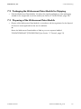
7.2 Packaging the Webconnect Data Module for Shipping . . . . . . . . . . 27
7.3 Disposing of the Webconnect Data Module . . . . . . . . . . . . . . . . . . . 27
8 Troubleshooting . . . . . . . . . . . . . . . . . . . . . . . . . . . . . . . . . . . . . 28
9 Technical Data . . . . . . . . . . . . . . . . . . . . . . . . . . . . . . . . . . . . . . 29
10 Compliance Information . . . . . . . . . . . . . . . . . . . . . . . . . . . . . . 30
11 Contact . . . . . . . . . . . . . . . . . . . . . . . . . . . . . . . . . . . . . . . . . . . . 31
8
WebconnectDM-IA-US_en-10
Installation Manual
SMA America, LLC
1 Information on this Document
1 Information on this Document
Validity
This document is valid for device type "SWDM-US-10" with firmware version 1.00.00.R or higher.
Target Group
This document is intended for qualified persons. Only qualified persons with the appropriate skills are
allowed to perform the tasks described in this document (see Section 2.2 "Skills of Qualified Persons",
page 13).
Symbols
Symbol
Explanation
Indicates a hazardous situation which, if not avoided, will result in death
or serious injury
Indicates a hazardous situation which, if not avoided, can result in death
or serious injury
Indicates a hazardous situation which, if not avoided, can result in minor
or moderate injury
Indicates a situation which, if not avoided, could result in property damage
Information that is important for a specific topic or goal, but is not
safety-relevant
☐
Indicates a requirement for meeting a specific goal
☑
Desired result
✖
A problem that could occur
Typographies
Typography
bold
Explanation
Example
• Elements on a user interface
• The value can be found in the
Energy field.
• Connections
• Select Settings.
• Elements to be selected
• Enter value 10 in the Minutes
field.
• Display texts
• Elements to be entered
>
• Connects several elements to
be selected
• Select Settings > Date.
[Button/Key]
• Button or key to be selected or
pressed
• Select [Next].
Installation Manual
WebconnectDM-IA-US_en-10
9
1 Information on this Document
SMA America, LLC
Nomenclature
Complete designation
Designation in this document
Electronic Solar Switch
ESS
PV plant
Plant
SMA America Production, LLC
SMA
SMA Solar Technology Canada Inc.
SMA
SMA Speedwire
Speedwire
SMA Webconnect Data Module
Webconnect Data Module
SMA Webconnect function
Webconnect function
SMA inverter
Inverter
Abbreviations
Abbreviations Designation
Explanation
AC
Alternating Current
‒
DHCP
Dynamic Host Configuration Protocol
Protocol for the dynamic assignment of
IP configurations
ESD
Electrostatic Discharge
‒
IP
Internet Protocol
‒
PIC
Product Identification Code
Identification key for registration in
Sunny Portal
RID
Registration Identifier
Registration key for registration in
Sunny Portal
Figures
In this document, the illustrations of the inverter type SB x000-TL-US-22 may deviate slightly.
10
WebconnectDM-IA-US_en-10
Installation Manual
SMA America, LLC
2 Safety
2 Safety
2.1 Intended Use
The Webconnect Data Module is a Webconnect communication interface for inverters which is based
on the SMA Speedwire technology.
Speedwire is a wire-based type of communication based on the Ethernet standard and the
communication protocol SMA Data2+. This enables inverter-optimized 10/100 Mbit data
transmission between Speedwire devices in PV plants.
The Webconnect function enables data transmission between the Internet portal Sunny Portal and the
inverters. This data transmission takes place via a router with Internet access. A PC with the software
Sunny Explorer* is also connected to the router.
* As of software version 1.04., Sunny Explorer is available free of charge at www.SMA-Solar.com.
The Webconnect Data Module performs the following tasks:
• Set-up of a Speedwire network
• Data exchange with the Internet portal Sunny Portal and Sunny Explorer via a router
A plant in Sunny Portal can consist of a maximum of four inverters with installed Webconnect Data
Module. The Speedwire network can be set up with the following optional topologies:
• Linear topology
• Star topology
Figure 1:
PV plant with a Speedwire network in linear topology (example)
Installation Manual
WebconnectDM-IA-US_en-10
11
2 Safety
Figure 2:
SMA America, LLC
PV plant with a Speedwire network in star topology (example)
The Webconnect Data Module is provided as a retrofit kit or is pre-installed in the inverter.
The Webconnect Data Module can only be installed in the following inverters as of
firmware version 2.51:
• Sunny Boy 3000TL-US-22 / 4000TL-US-22 / 5000TL-US-22
• Sunny Tripower 12000TL-US-10 / 15000TL-US-10 / 20000TL-US-10 / 24000TL-US-10
For information on firmware updates, refer to the Technical Description "Firmware Update with
SD Card" at www.SMA-Solar.com. For safety reasons, it is forbidden to modify the product or install
components that are not explicitly recommended for this product or distributed by SMA.
The enclosed documentation is an integral part of this product.
• Read and adhere to the documentation.
• Keep the documentation in a convenient place for future reference.
Only use the additional Webconnect Data Module in accordance with the specifications provided in
the enclosed documentation. Any other use can result in personal injury or material damage.
12
WebconnectDM-IA-US_en-10
Installation Manual
SMA America, LLC
2 Safety
2.2 Skills of Qualified Persons
The tasks described in this document must be performed by qualified persons only. Qualified persons
must have the following skills:
• Training in the installation and commissioning of electrical devices and plants
• Knowledge of how to deal with the dangers and risks associated with installation and operation
of electrical devices and plants
• Knowledge of all applicable standards and directives
• Knowledge of how an inverter works and is operated
• Acquaintance with this document and all safety precautions
2.3 Safety Precautions
Danger to life due to electric shock
Lethal voltages are present in the conductive parts of the inverter.
• Prior to performing any work on the inverter, disconnect the inverter from all voltage sources
on the AC and DC sides (see inverter installation manual). Observe the waiting time to allow
the capacitors to discharge.
Burns from hot surfaces
Some parts of the inverter enclosure may get hot during operation.
• During operation, touch the inverter on the enclosure lid only.
Damage to the inverter due to electrostatic discharge
By touching electronic components, you can damage or even destroy the inverter through
electrostatic discharge (ESD).
• Ground yourself before touching any inverter components.
Installation Manual
WebconnectDM-IA-US_en-10
13
3 Scope of Delivery
SMA America, LLC
3 Scope of Delivery
3.1 Order Option: Webconnect Data Module Pre-installed in the
Inverter
Check the scope of delivery for completeness and any visible external damage. Contact your
specialty retailer if the delivery is incomplete or you find any damage.
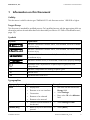
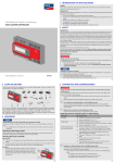
Figure 3:
Components included in delivery: Webconnect Data Module pre-installed in the inverter
Item
Quantity Designation
A
1
Installation manual
B
1
Cable gland
C
1
Sticker with PIC and RID for registration in Sunny Portal
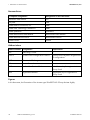
3.2 Order Option: Webconnect Data Module as Retrofit Kit
Check the scope of delivery for completeness and any visible external damage. Contact your
specialty retailer if the delivery is incomplete or you find any damage.
A
B
Components included in delivery: Webconnect Data Module as retrofit kit
Item
Quantity Designation
A
1
Webconnect Data Module
B
1
Installation manual
C
1
Cable gland
D
2
Sticker with PIC and RID for registration in Sunny Portal
14
D
n
tio
ra
ist xxx
eg xx
l R xx
rta xx
Po xx
y xx X
nn xx xXX
Su C: XX
PI D:
RI
Figure 4:
C
X
XX
XX
XX XX
XX X XX
XX XX XX
XX XX XX
XX XX XX
XX XX XX
XX XX XX
XX XX XX
XX XX
XX
A
B
WebconnectDM-IA-US_en-10
Installation Manual
SMA America, LLC
4 Product Description
4 Product Description
4.1 Webconnect Data Module
The Webconnect Data Module is a Webconnect communication interface for inverters which is based
on the SMA Speedwire technology.
Speedwire is a wire-based type of communication based on the Ethernet standard and the
communication protocol SMA Data2+. This enables inverter-optimized 10/100 Mbit data
transmission between Speedwire devices in PV plants.
The Webconnect function enables data transmission between the Internet portal Sunny Portal and the
inverters. This data transmission takes place via a router with Internet access. A PC with the software
Sunny Explorer* is also connected to the router.
* As of software version 1.04., Sunny Explorer is available free of charge at www.SMA-Solar.com.
The Webconnect Data Module performs the following tasks:
• Set-up of a Speedwire network
• Data exchange with the Internet portal Sunny Portal and Sunny Explorer via a router
The Webconnect Data Module is provided as a retrofit kit or is pre-installed in the inverter.
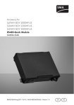
Figure 5:
Components of the Webconnect Data Module
Item
Designation
A
Hexagon socket screw
B
Network jack A
C
Network jack B
D
Ribbon cable plug
E
Ribbon cable
F
Type label
Installation Manual
WebconnectDM-IA-US_en-10
15
4 Product Description
SMA America, LLC
Sticker with PIC and RID
To activate the data module in the Sunny Portal, you will need the PIC and RID numbers printed on
the supplied sticker.
One of the two stickers should be affixed next to the type label on the inverter. The second sticker is
for the customer or plant operator.
4.2 Type Label
The type label clearly identifies the Webconnect Data Module. The type label is located in the top
right-hand corner at the front of the Webconnect Data Module. You can read the following data from
the type label:
• Product designation
• Device type and hardware version
• Serial number
• MAC Address
• PIC and RID
The information on the type label is required for safe use of the Webconnect Data Module and for
reference if customer support from the SMA Service Line is needed. The type label must be
permanently affixed to the Webconnect Data Module.
4.3 Cable Gland
The cable gland provides a sturdy, tightly sealed connection of the network cables with the inverter
enclosure. The cable gland also protects the inverter from dust and moisture penetration.
Figure 6:
Product description: Cable gland
Item
Designation
A
Filler-plug
B
Seal
C
Swivel nut
D
Counter nut
16
WebconnectDM-IA-US_en-10
Installation Manual
SMA America, LLC
5 Connection
5 Connection
5.1 Device Overview
Item
Designation
A
Flipped up display with screw
B
Cable route to the network jacks
C
Opening in the inverter enclosure with filler-plug
D
Mounting position of the Webconnect Data Module in the inverter
Installation Manual
WebconnectDM-IA-US_en-10
17
5 Connection
SMA America, LLC
5.2 Cabling of the Local Speedwire Network
The cable length and quality have an effect on the signal strength in the Speedwire network. Note the
following information regarding network cabling.
Interference of network data transmission due to AC cables
When AC cables are in operation, they generate an electromagnetic field which may induce
leading or lagging interference in network cables during data transmission.
• Lay the network cables using suitable fastening material and with a minimum clearance
of 2 in. (50 mm) to AC cables.
Cable requirements:
☐ Maximum cable length 328 ft. (100 m)
☐ Cross-section: min. 2 x 2 x 0.22 mm2 or min. 2 x 2 AWG 24
☐ Cable type: 100BaseTx, CAT5 with shielding S-UTP, F-UTP or higher
☐ UV-resistant for outdoor use
☐ Type of plug: RJ45
SMA recommends the following cable types:
• For outdoor use: SMA COMCAB-OUTxxx*
• For indoor use: SMA COMCAB-INxxx*
* available in the following lengths xxx = 328 ft. (100 m); 656 ft. (200 m); 1,640 ft (500 m); 3,280 ft. (1,000 m)
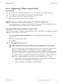
5.3 Installing the Webconnect Data Module in the Inverter
1.
Danger to life due to electric shock when opening the inverter
Lethal voltages are present in the conductive parts of the inverter.
• Disconnect the inverter from voltage sources on the AC and DC sides (see the inverter
installation manual). Observe the waiting time to allow the capacitors to discharge.
2. Open the inverter (see inverter installation manual).
3. Release the screw of the display far enough to
allow the display to be flipped up.
4. Flip the display up until it clicks into place.
18
WebconnectDM-IA-US_en-10
Installation Manual
SMA America, LLC
5. Insert the Webconnect Data Module and slide the
ribbon cable upwards behind the display. The key
at the top edge of the Webconnect Data Module
must fit into the hole in the plastic retainer in the
inverter.
5 Connection
2
1
6. Fasten the Webconnect Data Module hand-tight
with the hexagon socket screw.
7. Flip the display down.
8. Plug the ribbon cable plug onto the center
connector strip.
9. Attach one of the two supplied stickers with PIC and RID next to the type label of the inverter on
the inverter enclosure.
Installation Manual
WebconnectDM-IA-US_en-10
19
5 Connection
SMA America, LLC
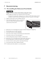
5.4 Connecting the Webconnect Data Module
Requirements:
☐ All electrical installations must be carried out according to all electrical standards applicable on
site and the National Electrical Code® (NE, ANSI/NFPA 70).
☐ Installations in Canada must be carried out in accordance with the applicable Canadian
standards.
Supplementary material (not included in the scope of delivery):
☐ Cable for connection of the Webconnect Data Module(see Section 5.2 "Cabling of the Local
Speedwire Network", page 18)
☐ If cables are routed in a conduit:
– 1 rain- or water-proof sleeve (diameter 1 in. (25.4 mm))
– 1 conduit (diameter: 1 in. (25.4 mm))
1.
Danger to life due to electric shock when opening the inverter
Lethal voltages are present in the conductive parts of the inverter.
• Disconnect the inverter from voltage sources on the AC and DC sides (see the inverter
installation manual). Observe the waiting time to allow the capacitors to discharge.
2. Open the inverter (see inverter installation manual).
3. Release the screw of the display far enough to
allow the display to be flipped up.
4. Flip the display up until it clicks into place.
5. Push the pre-mounted filler-plug out of the second
hole from the left in the inverter enclosure.
20
WebconnectDM-IA-US_en-10
Installation Manual
SMA America, LLC
5 Connection
6. If a conduit is to be used, proceed as follows:
• Insert one rain- or water-proof sleeve (diameter: 1 in. (25.4 mm)) into the enclosure opening
and tighten from the inside using a counter nut.
• Fit one conduit (diameter: 1 in. (25.4 mm) to the enclosure opening.
• Lead one or two cables through the conduit into the inverter.
7. If no conduit is to be used, proceed as follows:
• Attach the cable gland to the enclosure opening
with the counter nut.
• Unscrew the swivel nut of the cable gland on the
inverter.
• Press the seal out of the cable gland from the
inside.
• Depending on the plant topology, lead 1 or 2 network cables from the outside into the
inverter through the loose swivel nut and the cable gland.
Installation Manual
WebconnectDM-IA-US_en-10
21
5 Connection
SMA America, LLC
• Remove one of the filler-plugs from the seal for
each network cable.
• Insert 1 or 2 network cables into the seal. Route
the network cable plugs into the inverter to the
network jacks.
• Press the seal into the cable gland. Make sure that any unused cable openings are sealed
with filler-plugs.
• Screw the swivel nut of the cable gland on lightly.
8. Insert the network cables into the network jacks. This can be done in any order.
9. Fasten the swivel nut on the cable gland hand-tight. This will fix the network cables in place.
10. Flip the display down and fasten it hand-tight with the display screw.
11. Close inverter (see inverter installation manual).
12. Depending on the plant topology, connect at least one inverter directly to the router.
22
WebconnectDM-IA-US_en-10
Installation Manual
SMA America, LLC
6 Commissioning
6 Commissioning
6.1 Commissioning the Plant
Requirements:
☐ The Webconnect Data Module must be installed in the inverter (see Section 5.3 "Installing the
Webconnect Data Module in the Inverter", page 18).
☐ The Webconnect Data Module must be connected (see Section 5.4 "Connecting the
Webconnect Data Module", page 20).
☐ Depending on the plant topology, at least one inverter must be connected to the router.
☐ DHCP must be enabled in the router.
• Commission all inverters with installed Webconnect Data Module (see inverter operating
manual).
6.2 Plant Management with Sunny Explorer
6.2.1 Functions and Parameter Settings in Sunny Explorer
The following functions for plant management in Sunny Explorer are available:
• Overview of the plant status
• Graphic display of key plant data, device data and energy values
• Parameterization of individual devices or an entire device class
• Simple diagnostics due to display of faults and events
• Data export of inverter energy values and events in CSV format
• Device updates
You can change the following parameters in Sunny Explorer:
• Device name of the inverter
• Automatic IP configuration On/Off
• DNS-IP, gateway IP, IP address, subnet mask
• Webconnect function On/Off
Installation Manual
WebconnectDM-IA-US_en-10
23
6 Commissioning
SMA America, LLC
6.2.2 Connection to Sunny Explorer
Requirement:
☐ The plant must be commissioned (see Section 6.1 "Commissioning the Plant", page 23).
1. Connect the computer to the plant router with a network cable.
2. Start Sunny Explorer and create plant (see Sunny Explorer user manual).
6.3 Monitoring the Plant in Sunny Portal
Sunny Portal is an Internet portal for the monitoring of plants as well as the visualization and
presentation of plant data.
The following functions for monitoring your plant in Sunny Portal are available:
• Sending of status reports via e-mail to computer or cell phone
• Summary of key plant data in a plant overview and a plant profile
• Overview of the energy and power curves of your plant
• Report of plant yields in form of daily or monthly reports or as an annual summary
• Communication monitoring between Sunny Portal and a maximum of four inverters with
Webconnect function per plant
• Plant monitoring based on inverter comparison, provided that there are at least two inverters in
the plant
• Overview of device properties, parameters and messages
24
WebconnectDM-IA-US_en-10
Installation Manual
SMA America, LLC
6 Commissioning
6.3.1 Registering a Plant in Sunny Portal
Requirements:
☐ The plant must be commissioned (see Section 6.1 "Commissioning the Plant", page 23).
☐ PIC and RID must be available for the Webconnect Data Module.
☐ Your computer must have an Internet connection.
☐ A JavaScript-enabled browser must be installed.
Maximum permissible number of devices for a plant in Sunny Portal
In Sunny Portal you can manage several plants. A maximum of four interconnected inverters
with installed Webconnect Data Module per plant is permitted.
Starting the Plant Setup Assistant in Sunny Portal
The Plant Setup Assistant is a step-by-step guide of the processes required for user registration and the
registration of your plant in Sunny Portal
1. Go to www.SunnyPortal.com/Register (see user manual for Webconnect plants in
Sunny Portal).
☑ The Plant Setup Assistant opens.
2. Select [Next].
☑ The User Registration page opens.
Plant with Webconnect Data Module cannot be combined with other plants
Even if you already have a plant registered in Sunny Portal with another communication
device, e.g. Sunny WebBox, you will still need to create a separate plant with
Webconnect Data Module. It is not possible to combine the Webconnect Data Module
and other communication devices within one plant in Sunny Portal. Sunny Portal treats the
existing plant and the new plant with Webconnect Data Module as separate plants. An
inverter with integrated Webconnect function can be assigned to max. 1 plant.
• If applicable, delete any existing WebBox plant in Sunny Portal. When doing so,
ensure that the entire plant data is irrevocably erased.
• Create a new plant with Webconnect Data Module.
Installation Manual
WebconnectDM-IA-US_en-10
25
7 Decommissioning
SMA America, LLC
7 Decommissioning
7.1 Disassembling the Webconnect Data Module
1.
Danger to life due to electric shock when opening the inverter
Lethal voltages are present in the conductive parts of the inverter.
• Disconnect the inverter from voltage sources on the AC and DC sides (see the inverter
installation manual). Observe the waiting time to allow the capacitors to discharge.
2. Open the inverter (see inverter installation manual).
3. Press the left and right lock catches outwards and
remove the ribbon cable plug from the center
connector-strip of the inverter.
1
1
2
4. Release the screw of the display far enough to allow the display to be flipped up.
5. Flip the display up until it clicks into place.
6. Unscrew the swivel nut of the cable gland.
7. Remove the network cables from the Webconnect Data Module.
8. Unscrew the counter nut of the cable gland.
9. Pull the cable gland and network cables out of the inverter.
10. Release the screw of the Webconnect Data Module and remove it.
11. Flip the display down and fasten the display screw hand-tight.
12. Close the enclosure opening with an appropriate filler-plug.
13. Close inverter (see inverter installation manual).
☑ The Webconnect Data Module is now disassembled.
26
WebconnectDM-IA-US_en-10
Installation Manual
SMA America, LLC
7 Decommissioning
7.2 Packaging the Webconnect Data Module for Shipping
• Pack the Webconnect Data Module. Use either the original packaging or other packaging
suitable for the weight and size of the module (see Section 9 "Technical Data", page 29).
7.3 Disposing of the Webconnect Data Module
• Dispose of the Webconnect Data Module in accordance with the regulations for the disposal
of electronic waste applicable at the site of installation.
or
Return the Webconnect Data Module to SMA at your own expense labelled
"ZUR ENTSORGUNG" ("FOR DISPOSAL") (see Section 11 "Contact", page 31).
Installation Manual
WebconnectDM-IA-US_en-10
27
8 Troubleshooting
SMA America, LLC
8 Troubleshooting
Problem
Cause and corrective measures
The Webconnect Data Module There is no Speedwire connection.
cannot be accessed.
Corrective measures:
• Check whether all network cable plugs are inserted and
locked.
• Check whether all inverters in the plant are in operation.
• Check whether the plant router is switched on.
• Check whether the ribbon cable plug of the Webconnect
Data Module is correctly plugged into the center
connector- strip in the inverter.
The inverter does not recognize the Webconnect Data Module.
Corrective measures:
• Update the inverter firmware (download the update file
from www.SMA-Solar.com).
Firewall or IP filter settings are not correct.
Corrective measures:
• Adjust firewall or IP filter settings (see firewall or router
manual).
The Webconnect Data Module does not have a valid IP address.
Corrective measures:
• Double tap the computer to check whether a valid IP
address has been assigned. If N/A appears on the display,
no IP address has been assigned to the Webconnect Data
Module.
• Check whether DHCP is activated in the router or assign a
manual IP address to the Webconnect Data Module.
28
WebconnectDM-IA-US_en-10
Installation Manual
SMA America, LLC
9 Technical Data
9 Technical Data
General Data
Mounting location
Voltage supply
in the inverter
via inverter
Mechanical Data
Width x height x depth
2 7⁄8 in. x 3 7⁄16 in. x 1 3⁄8 in.
(73 mm x 88 mm x 34 mm)
Communication
Communication interface
Maximum cable length
Maximum data volume per Webconnect Data
Module per month
Additional data volume per hour when using the
Sunny Portal Live interface
Speedwire/Webconnect
328 ft. (100 m)
550 MB
600 kB
Connections
Type of plug
Number of RJ45 terminals
RJ45
2
Ambient Conditions during Operation
Ambient temperature
Relative humidity, non-condensing
Maximum height above sea level (MSL)
− 40°F … +185°F
( − 40°C … +85°C)
5% … 95%
9,842 ft. (3,000 m)
Ambient Conditions for Storage/Transport
Ambient temperature
− 40°F … +185°F
Relative humidity, non-condensing
Maximum height above sea level (MSL)
( − 40°C … +85°C)
10% … 100%
9,842 ft. (3,000 m)
Installation Manual
WebconnectDM-IA-US_en-10
29
10 Compliance Information
SMA America, LLC
10 Compliance Information
FCC Compliance
This device complies with Part 15 of the FCC Rules. Operation is subject to the following conditions:
1. This device may not cause harmful interference, and
2. This device must accept any interference received, including interference that may cause
undesired operation.
NOTE: This equipment has been tested and found to comply with the limits for a Class B digital device,
pursuant to Part 15 of the FCC Rules. These limits are designed to provide reasonable protection
against harmful interference in a residential installation. This equipment generates, uses, and can
radiate radio frequency energy and if not installed and used in accordance with the instructions, may
cause harmful interference to radio communications. However, there is no guarantee that interference
will not occur in a particular installation. If this equipment does cause harmful interference to radio or
television reception, which can be determined by turning the equipment off and on, the user is
encouraged to try to correct the interference by one or more of the following measures:
• Reorient or relocate the receiving antenna.
• Increase the separation between the equipment and the receiver.
• Connect the equipment into an outlet on a circuit different from that to which the receiver is
connected.
• Consult the dealer or an experienced radio/TV technician for help.
The user is cautioned that changes or modifications not expressly approved by
SMA America, LLC could void the user’s authority to operate this equipment.
IC Compliance
This device complies with Industry of Canada licence-exempt RSS standard(s). Operation is subject
to the following two conditions:
• This device may not cause interference, and
This device must accept any interference, including interferences that may cause undesired operation
of the device.
30
WebconnectDM-IA-US_en-10
Installation Manual
SMA America, LLC
11 Contact
11 Contact
If you have technical problems concerning our products, contact the SMA Service Line. We require
the following information in order to provide you with the necessary assistance:
• Type, serial number, and firmware version of the inverter
• Type, serial number, and firmware version of the Webconnect Data Module
• PIC and RID numbers of the Webconnect Data Module
• Number of connected inverters with integrated Webconnect function
Country
Company Name
Headquarters
SMA Service Line
America
SMA America, LLC
Rocklin, CA
+1 877-MY-SMATech (+1 877-697-6283)*
Canada
SMA Canada, Inc.
Toronto
+1 916 625-0870**
+1 877-MY-SMATech (+1 877-697-6283)***
* toll free for USA, Canada and Puerto Rico
** international
*** toll free for Canada
Installation Manual
WebconnectDM-IA-US_en-10
31
4."4PMBS5FDIOPMPHZ
XXX4."4PMBSDPN
4.""NFSJDB--$
XXX4.""NFSJDBDPN