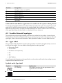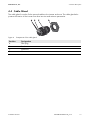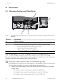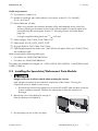
1
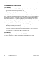
Installation Manual
SMA SPEEDWIRE/WEBCONNECT DATA MODULE
A
B
1
x
.BG
xxxx xx -10
FA:SER:PWDM
S
SWWEBCONDM-IA-US_en-14 | Version 1.4
AMERICAN ENGLISH
Legal Provisions
SMA America, LLC
Legal Provisions
Copyright © 2014 SMA America, LLC. All rights reserved.
No part of this document may be reproduced, stored in a retrieval system, or transmitted, in any form
or by any means, be it electronic, mechanical, photographic, magnetic or otherwise, without the prior
written permission of SMA America, LLC.
Neither SMA America, LLC nor SMA Solar Technology Canada Inc. makes representations, express
or implied, with respect to this documentation or any of the equipment and/or software it may
describe, including (with no limitation) any implied warranties of utility, merchantability, or fitness for
any particular purpose. All such warranties are expressly disclaimed. Neither SMA America, LLC nor
its distributors or dealers nor SMA Solar Technology Canada Inc. nor its distributors or dealers shall
be liable for any indirect, incidental, or consequential damages under any circumstances.
(The exclusion of implied warranties may not apply in all cases under some statutes, and thus the
above exclusion may not apply.)
Specifications are subject to change without notice. Every attempt has been made to make this
document complete, accurate and up-to-date. Readers are cautioned, however, that
SMA America, LLC and SMA Solar Technology Canada Inc. reserve the right to make changes
without notice and shall not be responsible for any damages, including indirect, incidental or
consequential damages, caused by reliance on the material presented, including, but not limited to,
omissions, typographical errors, arithmetical errors or listing errors in the content material.
All trademarks are recognized even if these are not marked separately. Missing designations do not
mean that a product or brand is not a registered trademark.
The Bluetooth® word mark and logos are registered trademarks owned by Bluetooth SIG, Inc. and
any use of such marks by SMA America, LLC and SMA Solar Technology Canada Inc. is under
license.
Modbus® is a registered trademark of Schneider Electric and is licensed by the Modbus
Organization, Inc.
Phillips® and Pozidriv® are registered trademarks of Phillips Screw Company.
Torx® is a registered trademark of Acument Global Technologies, Inc.
SMA America, LLC
3801 N. Havana Street
Denver, CO 80239 U.S.A.
SMA Solar Technology Canada Inc.
2425 Matheson Blvd. E
7th Floor
Mississauga, ON L4W 5K4
Canada
2
SWWEBCONDM-IA-US_en-14
Installation Manual
SMA America, LLC
IMPORTANT SAFETY INSTRUCTIONS
IMPORTANT SAFETY INSTRUCTIONS
SAVE THESE INSTRUCTIONS
This manual contains important instructions for the following product:
• SMA Speedwire/Webconnect Data Module
This manual must be followed during installation and maintenance.
The product is designed and tested according to international safety requirements, but as with all
electrical and electronic equipment, certain precautions must be observed when installing and/or
operating the product. To reduce the risk of personal injury and to ensure the safe installation and
operation of the product, you must carefully read and follow all instructions, cautions and warnings
in this manual.
Warnings in this document
A warning describes a hazard to equipment or personnel. It calls attention to a procedure or practice,
which, if not correctly performed or adhered to, could result in damage to or destruction of part or all
of the SMA equipment and/or other equipment connected to the SMA equipment or personal injury.
Symbol
Description
DANGER indicates a hazardous situation which, if not avoided, will result in
death or serious injury.
WARNING indicates a hazardous situation which, if not avoided, could result
in death or serious injury.
CAUTION indicates a hazardous situation which, if not avoided, could result
in minor or moderate injury.
NOTICE is used to address practices not related to personal injury.
Installation Manual
SWWEBCONDM-IA-US_en-14
3
General Warnings
SMA America, LLC
General Warnings
All electrical installations must be made in accordance with the local and National Electrical Code®
ANSI/NFPA 70 or the Canadian Electrical Code® CSA C22.1. This document does not and is not
intended to replace any local, state, provincial, federal or national laws, regulations or codes
applicable to the installation and use of the product, including without limitation applicable
electrical safety codes. All installations must conform with the laws, regulations, codes and
standards applicable in the jurisdiction of installation. SMA assumes no responsibility for the
compliance or noncompliance with such laws or codes in connection with the installation of the
product.
The product contains no user-serviceable parts.
For all repair and maintenance, always return the unit to an authorized SMA Service Center.
Before installing or using the product, read all of the instructions, cautions, and warnings in this
manual.
Wiring of the product must be made by qualified personnel only.
4
SWWEBCONDM-IA-US_en-14
Installation Manual
SMA America, LLC
Table of Contents
Table of Contents
1 Information on this Document. . . . . . . . . . . . . . . . . . . . . . . . . . . 7
1.1
1.2
1.3
1.4
1.5
1.6
1.7
Validity. . . . . . . . . . . . . . . . . . . . . . . . . . . . . . . . . . . . . . . . . . . . . . . . .
Target Group . . . . . . . . . . . . . . . . . . . . . . . . . . . . . . . . . . . . . . . . . . . .
Additional Information . . . . . . . . . . . . . . . . . . . . . . . . . . . . . . . . . . . . .
Symbols . . . . . . . . . . . . . . . . . . . . . . . . . . . . . . . . . . . . . . . . . . . . . . . .
Typographies. . . . . . . . . . . . . . . . . . . . . . . . . . . . . . . . . . . . . . . . . . . .
Nomenclature . . . . . . . . . . . . . . . . . . . . . . . . . . . . . . . . . . . . . . . . . . .
Illustrations . . . . . . . . . . . . . . . . . . . . . . . . . . . . . . . . . . . . . . . . . . . . . .
7
7
7
7
8
8
8
2 Safety . . . . . . . . . . . . . . . . . . . . . . . . . . . . . . . . . . . . . . . . . . . . . . 9
2.1
2.2
2.3
2.4
Intended Use . . . . . . . . . . . . . . . . . . . . . . . . . . . . . . . . . . . . . . . . . . . . 9
Safety Precautions . . . . . . . . . . . . . . . . . . . . . . . . . . . . . . . . . . . . . . . . 9
Operating Instructions . . . . . . . . . . . . . . . . . . . . . . . . . . . . . . . . . . . . 10
Supported Products . . . . . . . . . . . . . . . . . . . . . . . . . . . . . . . . . . . . . . 11
3 Scope of Delivery . . . . . . . . . . . . . . . . . . . . . . . . . . . . . . . . . . . . 12
4 Product Description . . . . . . . . . . . . . . . . . . . . . . . . . . . . . . . . . . 13
4.1
4.2
4.3
4.4
Speedwire/Webconnect Data Module . . . . . . . . . . . . . . . . . . . . . .
Possible Network Topologies . . . . . . . . . . . . . . . . . . . . . . . . . . . . . .
Type Label . . . . . . . . . . . . . . . . . . . . . . . . . . . . . . . . . . . . . . . . . . . . .
Cable Gland . . . . . . . . . . . . . . . . . . . . . . . . . . . . . . . . . . . . . . . . . . .
13
14
14
15
5 Connection . . . . . . . . . . . . . . . . . . . . . . . . . . . . . . . . . . . . . . . . . 16
5.1
5.2
5.3
5.4
Mounting Position and Cable Route . . . . . . . . . . . . . . . . . . . . . . . . .
Cable Requirements and Information on Cable Routing . . . . . . . . . .
Installing the Speedwire/Webconnect Data Module . . . . . . . . . . . .
Connecting the Speedwire/Webconnect Data Module . . . . . . . . . .
Installation Manual
SWWEBCONDM-IA-US_en-14
16
16
17
19
5
Table of Contents
SMA America, LLC
6 Commissioning . . . . . . . . . . . . . . . . . . . . . . . . . . . . . . . . . . . . . . 22
6.1 Commissioning a Large-Scale PV Power Plant with
Cluster Controller. . . . . . . . . . . . . . . . . . . . . . . . . . . . . . . . . . . . . . . . 22
6.2 Commissioning a Small-Scale PV System. . . . . . . . . . . . . . . . . . . . . . 22
6.3 Managing Small-Scale PV Systems with Sunny Explorer. . . . . . . . . . 23
6.3.1 Functions and Parameter Settings in Sunny Explorer . . . . . . . . . . . . 23
6.3.2 Creating a Small-Scale PV System in Sunny Explorer . . . . . . . . . . . 23
6.4 Configuring the Modbus Function . . . . . . . . . . . . . . . . . . . . . . . . . . . 23
6.5 PV System Registration in Sunny Portal . . . . . . . . . . . . . . . . . . . . . . . 24
6.5.1 Registering a Large-Scale PV Power Plant with
Cluster Controller in Sunny Portal . . . . . . . . . . . . . . . . . . . . . . . . . . 24
6.5.2 Registering a Small-Scale PV System in Sunny Portal. . . . . . . . . . . . 24
7 Decommissioning . . . . . . . . . . . . . . . . . . . . . . . . . . . . . . . . . . . . 26
7.1 Disassembling the Speedwire/Webconnect Data Module. . . . . . . . 26
7.2 Packaging the Speedwire/Webconnect Data Module for Shipping 26
7.3 Disposing of the Speedwire/Webconnect Data Module . . . . . . . . . 26
8 Troubleshooting . . . . . . . . . . . . . . . . . . . . . . . . . . . . . . . . . . . . . 27
9 Technical Data . . . . . . . . . . . . . . . . . . . . . . . . . . . . . . . . . . . . . . 29
10 Compliance Information . . . . . . . . . . . . . . . . . . . . . . . . . . . . . . 30
11 Contact . . . . . . . . . . . . . . . . . . . . . . . . . . . . . . . . . . . . . . . . . . . . 31
6
SWWEBCONDM-IA-US_en-14
Installation Manual
SMA America, LLC
1 Information on this Document
1 Information on this Document
1.1 Validity
This document is valid for device type "SWDM-10.GRUS" (Speedwire/Webconnect data module)
from hardware version A and firmware version 1.00.20.R.
1.2 Target Group
The tasks described in this document must only be performed by qualified persons. Qualified persons
must have the following skills:
• Training in the installation and commissioning of electrical devices and systems
• Knowledge of how to deal with the dangers and risks associated with installing and using
electrical devices and systems
• Knowledge of all applicable standards and directives
• Knowledge of how an inverter works and is operated
• Knowledge of and compliance with this document and all safety precautions
1.3 Additional Information
Links to additional information can be found at www.SMA-Solar.com:
Document title
Firmware Update with SD Card
SMA Speedwire Fieldbus
SMA Modbus® Interface
SunSpec® Modbus® Interface
Document type
Technical description
Technical information
Technical description
Technical description
1.4 Symbols
Symbol
☐
☑
✖
Installation Manual
Explanation
Information that is important for a specific topic or goal, but is not
safety-relevant
Indicates a requirement for meeting a specific goal
Desired result
A problem that might occur
SWWEBCONDM-IA-US_en-14
7
1 Information on this Document
SMA America, LLC
1.5 Typographies
Typography
Bold
Explanation
• Display texts
• Elements on a user interface
>
[Button/Key]
Example
• The value can be found in the
field Energy.
• Terminals
• Select Settings.
• Elements to be selected
• Enter the value 10 in the
Minutes field.
• Elements to be entered
• Connects several elements to
be selected
• Button or key to be selected or
pressed
• Select Settings > Date.
• Select [Next].
1.6 Nomenclature
Complete designation
Designation in this document
Photovoltaic system
PV system
Small-scale photovoltaic system
Small-scale PV system
Large-scale photovoltaic power plant
Large-scale PV power plant
SMA America Production, LLC
SMA
SMA Solar Technology Canada Inc.
SMA
SMA Cluster Controller
Cluster Controller
SMA Speedwire
Speedwire
SMA Speedwire/Webconnect data module
Speedwire/Webconnect data module
SMA Webconnect function
Webconnect function
SMA inverter
Inverter
1.7 Illustrations
The illustrations in this document have been created for Sunny Boy inverters so there may be slight
deviations in the case of Sunny Tripower inverters.
8
SWWEBCONDM-IA-US_en-14
Installation Manual
SMA America, LLC
2 Safety
2 Safety
2.1 Intended Use
The Speedwire/Webconnect data module is a Speedwire communication interface with Webconnect
function for inverters.
Speedwire is a cable-based type of communication based on the Ethernet standard and the
communication protocol SMA Data2+. This enables inverter-optimized 10/100 Mbit data
transmission between Speedwire devices in PV systems. The Webconnect function enables direct data
transmission between the inverters of a small-scale PV system and the Internet portal Sunny Portal
without any additional communication device and for a maximum of four inverters per Sunny Portal
system. For this, a Speedwire/Webconnect data module must be installed in each of the inverters.
You can access your Sunny Portal system from any computer with an Internet connection.
The inverter still complies with the applicable standards after the product has been installed.
For safety reasons, it is not permitted to modify the product or install components that are not explicitly
recommended or distributed by SMA for the product.
The type label must remain permanently attached to the product.
Use the Speedwire/Webconnect data module only in accordance with the enclosed documentation
and with the local standards and directives. Any other application may cause personal injury or
property damage.
The enclosed documentation is an integral part of this product.
• Read and observe the documentation.
• Keep the documentation in a convenient place for future reference.
2.2 Safety Precautions
This section contains safety precautions that must be observed at all times when working on or with
the product. To prevent personal injury and property damage and to ensure long-term operation of
the product, read this section carefully and follow all safety precautions at all times.
Danger to life due to electric shock when opening the inverter
High voltages are present in the conductive components of the inverter. Touching live components
results in death or serious injury.
• Prior to performing any work on the inverter, always disconnect the inverter from all voltage
sources on both AC and DC sides (see inverter installation manual). Observe the waiting time
to allow the capacitors to discharge.
Installation Manual
SWWEBCONDM-IA-US_en-14
9
2 Safety
SMA America, LLC
Risk of burns due to hot enclosure parts
Some parts of the inverter enclosure can get hot during operation. Touching these enclosure parts
can result in burn injuries.
• Do not touch any parts other than the lower enclosure lid of the inverter during operation.
Damage to the inverter or the Speedwire/Webconnect data module due to electrostatic
discharge
The internal electronic components of the inverter or the Speedwire/Webconnect data module can
be irreparably damaged by electrostatic discharge.
• Ground yourself before touching any electronic component.
2.3 Operating Instructions
High costs possible due to inappropriate Internet tariffs
When using the Webconnect function, a constant Internet connection is required.
Depending on the quality of the Internet connection, the data transfer volume for an inverter is
between 150 MB and 550 MB per month. If the system overview in Sunny Portal with live data
display is used, there will be an additional data volume of 600 kB per hour.
• Since the Internet connection to Sunny Portal is permanent, time-based billing systems should
be avoided. High costs could be incurred. SMA recommends using an Internet flat rate.
If UMTS is used, VoIP is required
If UMTS is used, VoIP (Voice over IP) is required to use the Webconnect function.
• Make sure that the UMTS provider can also provide a VoIP service.
10
SWWEBCONDM-IA-US_en-14
Installation Manual
SMA America, LLC
2 Safety
2.4 Supported Products
SMA Inverters
The Speedwire/Webconnect data module can only be installed in the following SMA inverters from
the specified inverter firmware version:
SMA inverter*
SB 3000TL-US-22
SB 3800TL-US-22
SB 4000TL-US-22
SB 5000TL-US-22
SB 6000TL-US-22
SB 7000TL-US-22
SB 7700TL-US-22
STP 12000TL-US-10
STP 15000TL-US-10
STP 20000TL-US-10
STP 24000TL-US-10
From inverter firmware version
2.60**
All
All
* For information on which of these SMA inverters with Speedwire/Webconnect data module support the mode interface of
the Speedwire/Webconnect data module, refer to the datasheet "SMA_Modbus-DB-en.xlsx" at www.SMA-Solar.com.
** If the firmware version of the inverter is less than 2.60, you must perform a firmware update for this inverter to version 2.60
or higher. For information on performing a firmware update, refer to the technical description "Firmware Update with
SD Card" at www.SMA-Solar.com.
Additional SMA Products
The Speedwire/Webconnect data module can be configured with the following communication
products:
• SMA Cluster Controller from firmware version 1.0
• Sunny Explorer from software version 1.06
• SMA Connection Assist from software version 1.00.8.R
Sunny Explorer and SMA Connection Assist are available free of charge at www.SMA-Solar.com.
Installation Manual
SWWEBCONDM-IA-US_en-14
11
3 Scope of Delivery
SMA America, LLC
3 Scope of Delivery
Check the scope of delivery for completeness and any visible external damage. Contact your
distributor if the scope of delivery is incomplete or damaged.
Order Option: Speedwire/Webconnect Data Module Pre-Installed in the Inverter
Figure 1:
Components of the order option "Speedwire/Webconnect data module pre-installed in the inverter"
Position
Quantity
Designation
A
1
Installation manual
B
1
Cable gland
C
1
Label with PIC (Product Identification Code, identification key for
registering devices in Sunny Portal) and RID (Registration Identifier,
registration code for registering devices in Sunny Portal)
Order Option: Speedwire/Webconnect Data Module as Retrofit Kit
A
D
n
tio
ra
ist xxx
e g xx
l R xx
r t a xx
Po xx
y xx X
n n xx X X
Su C : X Xx
PI D :
RI
Figure 2:
C
X
XX
XX
XX XX
XX X XX
XX XX XX
XX XX XX
XX XX XX
XX XX XX
XX XX XX
XX XX XX
XX XX
XX
A
B
B
Components of the order option "Speedwire/Webconnect data module as retrofit kit"
Position
Quantity
Designation
A
1
Speedwire/Webconnect data module (SWDM-US-10)
B
1
Installation manual
C
1
Cable gland
D
2
Label with PIC and RID for registration of a small-scale PV system in
Sunny Portal
12
SWWEBCONDM-IA-US_en-14
Installation Manual
SMA America, LLC
4 Product Description
4 Product Description
4.1 Speedwire/Webconnect Data Module
The Speedwire/Webconnect data module is a Speedwire communication interface with Webconnect
function for inverters.
Speedwire is a cable-based type of communication based on the Ethernet standard and the
communication protocol SMA Data2+. This enables inverter-optimized 10/100 Mbit data
transmission between Speedwire devices in PV systems.
The Webconnect function enables direct data transmission between the inverters of a small-scale
PV system and the Internet portal Sunny Portal without any additional communication device and for
a maximum of four inverters per Sunny Portal system. For this, a Speedwire/Webconnect data
module must be installed in each of the inverters. You can access your Sunny Portal system from any
computer with an Internet connection.
The Speedwire/Webconnect data module performs the following tasks:
• Setup of a Speedwire network in small-scale and large-scale PV systems
• Data exchange with Sunny Portal:
– In small-scale PV systems via a router with Internet connection
– In large-scale PV power plants via the Cluster Controller
• Data exchange with Sunny Explorer from software version 1.06
• The Modbus interface* of the Speedwire/Webconnect data module is designed for industrial
use and offers the following functions:
– Remote querying of measured values
– Remote setting of parameters
– Specification of setpoints for PV system control
The Speedwire/Webconnect data module is available as a retrofit kit or pre-installed in the inverter.
Figure 3:
Design of the Speedwire/Webconnect data module
* For information on which of the supported SMA inverters (see Section 2.4) support the Modbus interface of the Speedwire/
Webconnect data module, refer to the datasheet "SMA_Modbus-DB-en.xlsx" at www.SMA-Solar.com.
Installation Manual
SWWEBCONDM-IA-US_en-14
13
4 Product Description
SMA America, LLC
Position
Designation
A
Hexagon socket screw (AF 3)
B
Network port A
C
Network port B
D
Ribbon cable plug
E
Ribbon cable
F
Type label
Label with PIC and RID for registration of a small-scale PV system in Sunny Portal
To activate the Speedwire/Webconnect data module of a small-scale system in Sunny Portal, you will
need the PIC and RID numbers printed on the supplied label. After installation of the Speedwire/
Webconnect data module, one label should be attached to the exterior of the inverter in the vicinity
of the type label. Keep the other label in a safe place for future reference.
4.2 Possible Network Topologies
The possible network topologies depend on the devices used and on the number of network ports.
The Speedwire/Webconnect data module has two network ports. For further information on network
topologies, refer to the technical information "SMA Speedwire Fieldbus" at www.SMA-Solar.com.
4.3 Type Label
The type label clearly identifies the product. The type label is located in the right-hand top corner on
the front of the product. You can read the following data from the type label:
• Device type (Type)
• Serial number
• Hardware version (Version)
• PIC
• RID
• MAC address
You will require the information on the type label to use the product safely and when seeking customer
support from the SMA Service Line.
Symbols on the Type Label
Symbol
14
Designation
FCC marking
Explanation
The product complies with the requirements of the
applicable FCC standards.
Data matrix code
2D code for device-specific characteristics
SWWEBCONDM-IA-US_en-14
Installation Manual
SMA America, LLC
4 Product Description
4.4 Cable Gland
The cable gland is used to fix the network cables to the inverter enclosure. The cable gland also
protects the interior of the inverter from dust intrusion and moisture penetration.
Figure 4:
Components of the cable gland
Position
A
B
C
D
Installation Manual
Designation
Filler plug
Seal
Swivel nut
Counter nut
SWWEBCONDM-IA-US_en-14
15
5 Connection
SMA America, LLC
5 Connection
5.1 Mounting Position and Cable Route
Figure 5:
Position
A
B
C
Mounting position and cable route in the inverter with the lower enclosure lid open and the display
flipped up
Designation
Flipped up display
Cable route to the network ports
Inverter enclosure opening for cable gland or conduit fitting and conduit
• Size for Sunny Boy inverters (SB): 3⁄4 in (19 mm)
D
• Size for Sunny Tripower inverters (STP):
1 3⁄32 in (27.8 mm) to 1 7⁄64 in (28.0 mm)
Mounting position of the Speedwire/Webconnect data module in the inverter
5.2 Cable Requirements and Information on Cable Routing
The cable length and cable quality affect the signal strength in the Speedwire network. Observe the
following cable requirements and the cable routing information.
Interference in data transmission due to unshielded energy cables
If unshielded power cables are used, they generate an electromagnetic field during operation
which may induce interference in network cables during data transmission.
• When laying network cables, observe the following minimum clearances to unshielded
energy cables:
– For installation without separating strip: at least 8 in (200 mm)
– For installation with aluminum separating strip: at least 4 in (100 mm)
– For installation with steel separating strip: at least 2 in (50 mm)
16
SWWEBCONDM-IA-US_en-14
Installation Manual
SMA America, LLC
5 Connection
Cable requirements:
☐ UV-resistant for outdoor use
☐ Number of conductor pairs and conductor cross-section: at least 2 x 2 x 24 AWG
(2 x 2 x 0.22 mm2)
☐ External diameter of cable:
– When using conduits: the maximum diameter of the cable depends on the size of the
enclosure opening at the bottom of the inverter and the number of network cables to be
inserted through the opening (see Section 5.1 "Mounting Position and Cable Route",
page 16).
– If using the supplied cable gland: max. 17⁄48 in (9 mm)
☐ Cable category: Cat5, Cat5e, Cat6, Cat6a, Cat7
☐ Cable shield: SF/UTP, S/UTP, SF/FTP, S/FTP
☐ Plug type: RJ45 for Cat5, Cat5e, Cat6, Cat6a
☐ Cable length between two nodes: max. 164 ft (50 m) with patch cable, max. 328 ft (100 m)
with installation cable
SMA recommends the following cable types:
• For outdoor use: SMA COMCAB-OUTxxx
• For indoor use: SMA COMCAB-INxxx*
The cables are available in the lengths xxx = 328 ft (100 m), 656 ft (200 m), 1,640 ft (500 m) and
3,280 ft (1,000 m).
5.3 Installing the Speedwire/Webconnect Data Module
1.
Danger to life due to electric shock when opening the inverter
High voltages are present in the conductive components of the inverter. Touching live
components results in death or serious injury.
• Disconnect the inverter from voltage sources on the AC and DC sides and open it (see the
inverter installation manual). Observe the waiting time to allow the capacitors to
discharge.
2. Release the screw of the display far enough to
allow the display to be flipped up.
3. Flip the display up until it clicks into place.
Installation Manual
SWWEBCONDM-IA-US_en-14
17
5 Connection
SMA America, LLC
4. Push the pre-mounted filler plug out of the second
hole from the left in the inverter enclosure and retain
it for future decommissioning.
5. Attach the cable gland to the enclosure opening
using the counter nut.
6. Insert the Speedwire/Webconnect data module
and push the ribbon cable upwards behind the
display. The key on the top edge of the Speedwire/
Webconnect data module must fit into the hole in
the plastic retainer in the inverter.
2
1
7. Fasten the Speedwire/Webconnect data module
hand-tight with a torque of 13 in-lb (1.5 Nm) using
the hexagon socket screw (AF 3).
8. Flip the display down.
18
SWWEBCONDM-IA-US_en-14
Installation Manual
SMA America, LLC
5 Connection
9. Plug the ribbon cable plug onto the center
connector strip.
10. Stick one of the labels with the data for registration in Sunny Portal (PIC and RID) on the outside
of the inverter in the vicinity of the type label.
11. If you do not wish to proceed immediately with the connection of the Speedwire/Webconnect
data module, close the inverter (see inverter installation manual).
5.4 Connecting the Speedwire/Webconnect Data Module
Depending on the system topology you require, you will need to connect either one or two cables to
the Speedwire/Webconnect data module.
Requirements:
☐ All electrical installations must be carried out in accordance with the electrical standards
applicable on site and the National Electrical Code® (NE, ANSI/NFPA 70).
☐ Installations in Canada must comply with the applicable Canadian standards.
☐ The network cables must be pre-assembled in accordance with the system topology and the
cable requirements (see Section 5.2, page 16).
Additionally required material (not included in the scope of delivery):
☐ Network cable (see Section 5.2 "Cable Requirements and Information on Cable Routing",
page 16)
☐ If cables are routed in a conduit:
– 1 rain-tight or wet-strength conduit fitting (diameter: 3/4 in)
– 1 conduit (diameter: 3/4 in)
Procedure:
1.
Danger to life due to electric shock when opening the inverter
High voltages are present in the conductive components of the inverter. Touching live
components results in death or serious injury.
• If the inverter has not yet been opened, disconnect the inverter from voltage sources on
the AC and DC sides and open it (see the inverter installation manual). Observe the
waiting time to allow the capacitors to discharge.
2. Flip the display up until it clicks into place.
Installation Manual
SWWEBCONDM-IA-US_en-14
19
5 Connection
SMA America, LLC
3. Push the pre-mounted filler plug out of the second
hole from the left in the inverter enclosure.
4. If a conduit is to be used, proceed as follows:
• Insert one rain-tight or wet-strength conduit fitting into the enclosure opening and fasten from
the inside using a counter nut.
• Install one conduit at the enclosure opening.
• Lead one or two cables through the conduit into the inverter.
• Insert the network cables into the network ports. This can be done in any order.
5. If no conduit is to be used, proceed as follows:
• Attach cable gland to the enclosure opening
using the counter nut.
• Unscrew the swivel nut of the cable gland on
the inverter.
• Press the seal out of the cable gland from the
inside.
20
SWWEBCONDM-IA-US_en-14
Installation Manual
SMA America, LLC
5 Connection
• Lead the network cables from the outside through the released swivel nut and the cable
gland into the inverter.
• For each network cable, remove one of the
filler plugs from the seal and retain for later
decommissioning.
• Lead the network cables through the swivel nut
and into the seal. The network cable plugs must
lead to the network ports in the inverter.
• Press the seal into the cable gland. Make sure that any unused cable openings are sealed
with filler plugs.
• Screw the swivel nut of the cable gland on loosely.
• Insert the network cables into the network ports. This can be done in any order.
• Fasten the swivel nut on the cable gland hand-tight. This will fix the network cables in place.
6. Flip the display down and fasten it hand-tight with the screw.
7. Close the inverter (see inverter installation manual).
8. In a small-scale PV system, depending on the system topology connect one or more inverter(s)
directly to the router.
9. In a large-scale PV power plant with Cluster Controller, connect the Cluster Controller to the
Speedwire network in accordance with the required network topology (see the
Cluster Controller installation manual).
Installation Manual
SWWEBCONDM-IA-US_en-14
21
6 Commissioning
SMA America, LLC
6 Commissioning
6.1 Commissioning a Large-Scale PV Power Plant with
Cluster Controller
Requirements:
☐ Speedwire/Webconnect data modules must be installed in the inverters (see Section 5.3,
page 17).
☐ Speedwire/Webconnect data modules must be connected (see Section 5.4, page 19).
☐ The Cluster Controller must be connected to the Speedwire network in accordance with the
required network topology (see installation manual of the Cluster Controller).
Procedure:
1. Commission all inverters (see inverter installation manual).
2. For optimum operation of large-scale PV power plants with Cluster Controller, deactivate the
Webconnect function of the inverters with installed Speedwire/Webconnect data module
(see user manual of the Cluster Controller). In large-scale PV power plants with
Cluster Controller, communication with Sunny Portal takes place via the Cluster Controller itself.
6.2 Commissioning a Small-Scale PV System
Requirements:
☐ Speedwire/Webconnect data modules must be installed in the inverters (see Section 5.3,
page 17).
☐ Speedwire/Webconnect data module must be connected (see Section 5.4, page 19).
☐ There must be a router with Internet connection in the local network of the PV system.
☐ At least one inverter must be connected to the router.
☐ If the IP addresses in the local network are to be assigned dynamically, DHCP must be activated
in the router (see the router manual). If you do not want to use DHCP or your router does not
support DHCP, use either the SMA Connection Assist or Sunny Explorer to integrate the inverters
with Speedwire/Webconnect data module into the local network (see Section 2.4 "Supported
Products", page 11).
Procedure:
• Commission all inverters (see inverter installation manual).
22
SWWEBCONDM-IA-US_en-14
Installation Manual
SMA America, LLC
6 Commissioning
6.3 Managing Small-Scale PV Systems with Sunny Explorer
6.3.1 Functions and Parameter Settings in Sunny Explorer
The following functions for small-scale PV system management are available in Sunny Explorer:
• Overview of the PV system status
• Graphic display of key PV system data, device data and the respective energy values
• Parameterization of individual devices or entire device classes
• Simple diagnostics thanks to display of faults and events
• Data export of inverter energy values and events in CSV format
• Device updates
You can change the following parameters with Sunny Explorer:
• Device name of the inverter
• Automatic IP configuration On/Off
• DNS-IP, gateway IP, IP address, subnet mask
• Webconnect function On/Off
• Modbus function On/Off
6.3.2 Creating a Small-Scale PV System in Sunny Explorer
Requirements:
☐ The small-scale PV system must be commissioned (see Section 6.2, page 22).
☐ Sunny Explorer must be installed on the computer (see Section 2.4 "Supported Products",
page 11).
Procedure:
1. Connect the computer to the PV system router with a network cable.
2. If you have used the SMA Connection Assist for static network configuration, ensure that the
SMA Connection Assist has terminated.
3. Start Sunny Explorer and create a Speedwire system for the small-scale PV system in
Sunny Explorer (see Sunny Explorer help).
6.4 Configuring the Modbus Function
If you wish to access SMA inverters with Modbus interface, make sure that the Modbus connection
of the devices has been configured correctly. In each of the devices with Modbus, the same port must
be configured for Modbus communication. The Modbus function is deactivated by default in the
Speedwire/Webconnect data module, and port 502 is configured for the Modbus servers TCP and
UDP. Information on how to use the Modbus interface can be found in the technical description
"SMA Modbus® Interface" or "SunSpec®Modbus® Interface" at www.SMA-Solar.com.
For information on which of the supported SMA inverters (see Section 2.4) support the Modbus
interface of the Speedwire/Webconnect data module, refer to the datasheet
"SMA_Modbus-DB-en.xlsx" at www.SMA-Solar.com.
Installation Manual
SWWEBCONDM-IA-US_en-14
23
6 Commissioning
SMA America, LLC
Procedure:
• If necessary, adjust the preset ports in the Speedwire/Webconnect data module for Modbus
communication (see technical description "SMA Modbus® Interface" or "SunSpec®Modbus®
Interface" at www.SMA-Solar.com).
6.5 PV System Registration in Sunny Portal
6.5.1 Registering a Large-Scale PV Power Plant with
Cluster Controller in Sunny Portal
Requirements:
☐ The large-scale PV power plant with Cluster Controller must be be commissioned
(see Section 6.1, page 22).
☐ The computer must have an Internet connection.
☐ The Cluster Controller must be connected to a router with Internet connection
(see installation manual of the Cluster Controller).
☐ JavaScript must be enabled in the web browser.
Procedure:
• In large-scale PV power plants with Cluster Controller, carry out registration in Sunny Portal via
the user interface of the Cluster Controller (see user manual of the Cluster Controller).
6.5.2 Registering a Small-Scale PV System in Sunny Portal
Requirements:
☐ The small-scale PV system must be commissioned (see Section 6.2, page 22).
☐ PIC and RID of the Speedwire/Webconnect data module must be available.
☐ Your computer must have an Internet connection.
☐ JavaScript must be enabled in the web browser.
☐ On the router, all UDP ports > 1024 must be open for outgoing connections. If there is a firewall
installed on the router, you may have to adjust the firewall rules.
☐ The outgoing router connections must be enabled for all Internet destinations (target IP, target
port). If there is a firewall installed on the router, you may have to adjust the firewall rules.
☐ In routers with NAT (Network Address Translation), no port forwarding should be set up.
This will help prevent potential communication problems.
☐ There must be no packet filtering or manipulation for SIP packets on the router.
Maximum permissible number of devices for a small-scale PV system in Sunny Portal
In Sunny Portal, a maximum of four inverters with installed Speedwire/Webconnect data
module is permitted per small-scale PV system.
24
SWWEBCONDM-IA-US_en-14
Installation Manual
SMA America, LLC
6 Commissioning
Small-scale PV system with Speedwire/Webconnect data module cannot be
combined with other PV systems
If you already have a PV system set up in Sunny Portal with a different communication device,
e.g. Sunny WebBox, you will still need to create a separate small-scale PV system with
Speedwire/Webconnect data module. It is not possible to combine the Speedwire/
Webconnect data module and other communication devices in one system in Sunny Portal.
Sunny Portal treats the existing PV system and the new small-scale PV system with Speedwire/
Webconnect data module as independent PV systems.
• Create a new small-scale PV system with Speedwire/Webconnect data module.
Replacement of the Speedwire/Webconnect data module in the inverter
If you have replaced the Speedwire/Webconnect data module in the inverter with a new
Speedwire/Webconnect data module, the PIC and the RID of the inverter will be changed.
Therefore, you will also need to replace the inverter in Sunny Portal using the Plant Setup
Assistant (see the Sunny Portal user manual). In the Plant Setup Assistant, you must enter the PIC
and the RID of the new Speedwire/Webconnect data module.
Starting the Plant Setup Assistant in Sunny Portal
The Plant Setup Assistant is a step-by-step guide to the procedure required for user registration and
the registration of your PV system in Sunny Portal
Procedure:
1. Go to www.SunnyPortal.com.
2. Select [Plant Setup Assistant].
☑ The Plant Setup Assistant opens.
3. Follow the instructions of the Plant Setup Assistant.
Installation Manual
SWWEBCONDM-IA-US_en-14
25
7 Decommissioning
SMA America, LLC
7 Decommissioning
7.1 Disassembling the Speedwire/Webconnect Data Module
1.
Danger to life due to electric shock when opening the inverter
High voltages are present in the conductive components of the inverter. Touching live
components results in death or serious injury.
• Disconnect the inverter from voltage sources on the AC and DC sides and open it
(see the inverter installation manual). Observe the waiting time to allow the capacitors to
discharge.
2. Press the left-hand and right-hand lock hooks
outwards and remove the ribbon cable plug from
the center connector strip of the inverter.
1
1
2
3. Release the screw of the display far enough to allow the display to flip up.
4. Flip the display up until it clicks into place.
5. Unscrew the swivel nut of the cable gland.
6. Remove the network cables from the Speedwire/Webconnect data module.
7. Unscrew the counter nut of the cable gland or conduit fitting.
8. Pull the cable gland or conduit fitting with conduit and the cables out of the inverter.
9. Release the hexagon socket screw of the Speedwire/Webconnect data module (AF 3) and
remove the module.
10. Flip the display down and fasten the display screw hand-tight.
11. Seal the enclosure opening of the inverter with the corresponding filler plug.
12. Close the inverter (see inverter installation manual).
7.2 Packaging the Speedwire/Webconnect Data Module for
Shipping
• Package the Speedwire/Webconnect data module for shipping. Use the original packaging or
packaging that is suitable for the weight and size of the Speedwire/Webconnect data module
(see Section 9 "Technical Data", page 29).
7.3 Disposing of the Speedwire/Webconnect Data Module
• Dispose of the Speedwire/Webconnect data module in accordance with the regulations for
disposal of electronic waste applicable at the installation site.
26
SWWEBCONDM-IA-US_en-14
Installation Manual
SMA America, LLC
8 Troubleshooting
8 Troubleshooting
Corrective measures for Modbus errors
Corrective measures for Modbus errors can be found in the technical description
"SMA Modbus® Interface" or "SunSpec®Modbus® Interface".
Problem
The Speedwire/
Webconnect data
module cannot be
accessed.
Cause and corrective measure
Possibly, there is no Speedwire connection.
Corrective measures:
• Ensure that all network cable plugs are inserted and locked.
• Ensure that all inverters in the PV system are in operation.
• Make sure that the PV system router is switched on.
• Make sure that the ribbon cable plug of the Speedwire/
Webconnect data module is correctly plugged into the center
connector strip in the inverter.
Possibly, the Speedwire/ Webconnect data module does not have a valid
IP address.
Corrective measures:
• Make sure DHCP is enabled for the router
or
• Use SMA Connection Assist or Sunny Explorer to assign an
appropriate static IP address to the Speedwire/Webconnect data
module. You can obtain the Sunny Explorer and SMA Connection
Assist software free of charge from the download area at
www.SMA-Solar.com.
Possibly, the firewall has not been configured correctly.
Corrective measures:
• Enable ports 3478 and 9523 in the firewall (see firewall manual).
Possibly, the UDP ports in the router are not open for outgoing
connections.
Corrective measures:
• Open the UDP ports > 1024 in the router for outgoing connections.
Possibly, the IP filter has not been configured correctly.
Corrective measures:
• Adjust IP filter settings (see router manual).
Installation Manual
SWWEBCONDM-IA-US_en-14
27
8 Troubleshooting
Problem
The Speedwire/
Webconnect data
module cannot be
accessed.
SMA America, LLC
Cause and corrective measure
Possibly, there is a packet filter or SIP packet manipulation activated in the
router.
Corrective measures:
• Disable packet filters or SIP packet manipulation in the router.
Possibly, port forwarding options have been set up in a router with NAT
function (Network Address Translation).
Corrective measures:
• Remove the port forwarding options in the router with NAT function.
Possibly, the inverter does not recognize the Speedwire/Webconnect
data module. The firmware version of the inverter is not supported
(see Section 2.4, page 11).
Corrective measures:
• Perform a firmware update on the inverter. For information on
performing a firmware update, refer to the technical description
"Firmware Update with SD Card" at www.SMA-Solar.com.
28
SWWEBCONDM-IA-US_en-14
Installation Manual
SMA America, LLC
9 Technical Data
9 Technical Data
General Information
Mounting location
In the inverter
Voltage supply
Via the inverter
Mechanical Data
Width x height x depth
2 7⁄8 in x 3 7⁄16 in x 1 3⁄8 in
(73 mm x 88 mm x 34 mm)
Communication
Communication interface
Maximum cable length
Speedwire/Webconnect
328 ft (100 m)
Protocols
Data interface
SMA Modbus, SunSpec
Terminals
Type of plug
Number of RJ45 terminals
RJ45
2
Ambient Conditions for Storage/Transport
Ambient temperature
− 40°F to +185°F
( − 40°C to +85°C)
Relative humidity, non-condensing
Installation Manual
10% to 100%
SWWEBCONDM-IA-US_en-14
29
10 Compliance Information
SMA America, LLC
10 Compliance Information
FCC Compliance
This device complies with Part 15 of the FCC Rules. Operation is subject to the following conditions:
1. This device may not cause harmful interference, and
2. This device must accept any interference received, including interference that may cause
undesired operation.
The user is cautioned that changes or modifications not expressly approved by SMA America, LLC
could void the user’s authority to operate this equipment.
NOTE: This equipment has been tested and found to comply with the limits for a Class B digital device,
pursuant to Part 15 of the FCC Rules. These limits are designed to provide reasonable protection
against harmful interference in a residential installation. This equipment generates, uses, and can
radiate radio frequency energy and if not installed and used in accordance with the instructions, may
cause harmful interference to radio communications. However, there is no guarantee that interference
will not occur in a particular installation. If this equipment does cause harmful interference to radio or
television reception, which can be determined by turning the equipment off and on, the user is
encouraged to try to correct the interference by one or more of the following measures:
• Reorient or relocate the receiving antenna.
• Increase the separation between the equipment and the receiver.
• Connect the equipment into an outlet on a circuit different from that to which the receiver is
connected.
• Consult the dealer or an experienced radio/TV technician for help.
IC Compliance
This Class B digital apparatus complies with Canadian ICES-003.
Cet appareil numérique de la classe B est conforme à la norme NMB-003 du Canada.
30
SWWEBCONDM-IA-US_en-14
Installation Manual
SMA America, LLC
11 Contact
11 Contact
If you have technical problems with our products, please contact the SMA Service Line. We need the
following information in order to provide you with the necessary assistance:
• Inverter:
– Device type and serial number (see type label)
– Firmware version (tap the inverter display twice or see Sunny Portal or Sunny Explorer)
• Speedwire/Webconnect data module:
– Device type, serial number and hardware version (see type label)
– Number of Speedwire/Webconnect data modules connected
• In large-scale PV power plants:
– Serial number and firmware version of the Cluster Controller
• In small-scale PV systems:
– Name of your Sunny Portal system
– PIC and RID of the Speedwire/Webconnect data module
United States/ SMA America, LLC
Estados
Rocklin, CA
Unidos
+1 877-MY-SMATech (+1 877-697-6283)*
Canada/
Canadá
+1 877-MY-SMATech (+1 877-697-6283)***
SMA Canada, Inc.
+1 916 625-0870**
Toronto
* toll free for USA, Canada and Puerto Rico / Llamada gratuita en EE. UU., Canadá y Puerto Rico
** international / internacional
*** toll free for Canada / gratuit pour le Canada
Installation Manual
SWWEBCONDM-IA-US_en-14
31
SMA Solar Technology
www.SMA-Solar.com