1
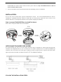
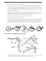
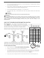
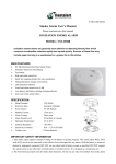
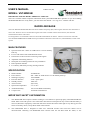
USER’S MANUAL
MODEL: VST-WB598I
V-MUL-033(A0)
IMPORTANT! PLEASE READ CAREFULLY AND SAVE.
This user’s manual contains important information about your RadioLINK Base operation. If you are installing
the RadioLINK Base for use by others, you must leave this manual—or a copy of it—with the end user.
RADIOLINK BASE
The VST-WB598I RadioLINK Base transmits a Radio Frequency (RF) alarm signal when the unit attached to it
senses fire. When it receives an RF alarm signal from other VS-TOP wireless alarm alarms, the attached
smoke/CO/heat alarm will sound.
It is designed for use with Mains Powered VS-TOP Smoke/Heat/CO Alarms. The base can also be used with
VST-S598I/S598IH/H598I/C598IH alarms provided that a Remote Control device (VST-WB598I) is used in the
system.
MAIN FEATURES
¾
¾
¾
¾
¾
¾
¾
Operated with 220~240V AC 50Hz and 2*1.5V DC Battery
back-up
For use with VST wired smoke/heat/CO alarms
Interconnect to other wireless units using radio signals
Adjustable transmitting function
With quick fix mounting bracket for easy installation
LED operation indicator
Low-battery and battery missing warning indicator
SPECIFICATION
¾
¾
¾
¾
¾
¾
¾
¾
¾
Model Number:
Power Source:
Working Frequency:
Emission distance:
Standby Current:
Alarm Current:
Operation Temperature:
Ambient Humidity:
Compact size:
VST-WB598I
220~240V AC 50Hz and 2*1.5V DC Battery back-up
433/868MHz
>60m(open space)
10uA max
35mA max
5℃ to 45℃
10% to 90% Relative Humidity
116mmX116mmX47mm
IMPORTANT SAFETY INFORMATION
1.
This RadioLINK base requires constant working 2*1.5V batteries to operate properly. This RadioLINK base
WILL NOT work if DC power is not connected or has failed or interrupted for any reason AND the battery is
removed, drained or improperly connected. DO NOT connect this alarm strobe light to any other type of fire
alarm or auxiliary device, except those listed in this manual.
2.
This RadioLINK base is designed to make sure VST-TOP wireless and wired fire alarms can be
interconnected. Generally, one RadioLINK base connects with one VS-TOP wired fire alarm; or one
RaidoLINK base connects with a wired fire alarm system. However, only one RadioLINK base is allowed
in one wired fire alarm system.
3.
Observe and follow all local and national electrical and building codes for installation.
INSTALLATION
For use only with VS-TOP mains powered smoke/heat/CO alarms. The VS-TOP RadioLINK base must be
installed by a qualified electrician. Failure to install this unit correctly may expose the user to shock or fire
hazards. This unit is not waterproof and must not be exposed to dripping or splashing.
How to connect RadioLINK Base to wired fire alarms
Please refer to the picture FIG1 below for installation.
INTERCONNECTING WIRED FIRE ALARMS
For interconnecting line, only use #14-#18 AWG minimum solid or stranded wire. When being interconnected,
maximum wire length between any two is 1500 feet for #18 AWG or 4000 feet for #14 AWG (20 OHMS loop
resistance). Do not connect to any other type or model fire alarms except the ones we specify. The alarm strobe
light is powered by 220-240V AC 50Hz and with 2*1.5V AA batteries back-up.
FOLLOW THE INSTALLATION STEPS
1.
Turn off power at main fuse box or circuit breaker.
2.
Set the wireless interconnection. (SEE How to Set the Wireless Interconnection Function)
3.
Pull out the battery compartment and unpack batteries (See FIG2). Then install the batteries to the
compartment. NOTE POLARITY OF CONNECTIONS. To engage tamper-resist feature, insert pin
into notch on edge of battery compartment after batteries are installed and battery compartment is back
to its position.(See FIG3, FIG4)
4.
The interconnect wire passes through the hole of the RadioLINK Base and connect the wire to the wire
holder. Ensure the wiring order is correct. (Brown wire connects with live wire, blue wire connects with
earth wire, yellow wire connects with interconnect wire.) See FIG5 and FIG6.
5.
Secure the wireless RadioLINK base to ceiling or wall with mounting screws.
6.
Turn on power at main fuse box or circuit breaker.
7.
Press the test button on the VS-TOP wireless remote control switch or wireless fire alarms which are in
the same fire alarm system as the RadioLINK base. The fire alarm which connects to the RadioLINK
base will sound. If press the test button of the fire alarm which connects to the RadioLINK base, the
wireless remote control will have alarm indication and fire alarm in the same alarm system will sound.
DO NOT INSTALL WIRELESS RADIOLINK BASE
1.
Near appliances or areas where normal combustion regularly occurs (kitchens, near furnaces, hot water
heaters). Use specialized smoke alarm with unwanted alarm control for this areas.
2.
In areas with high humidity, like bathrooms or areas near dishwashers or washing machines. Install at
least 10 feet away from these areas.
3.
Near air returns or heating and cooling supply vents. Install at least 3 feet away from these areas. The air
could blow smoke away from the detector, interrupting its alarm.
4.
In rooms where temperatures may fall below 5℃ or rise above 45℃.
5.
In extremely dusty, dirty, or insect-infested areas where loose particles interfere with smoke alarm
operation.
WARNING!
Incorrect orientation will result in a decrease in operational effectiveness.
WARNING!
Make sure the RadioLINK base is not receiving excessively noisy power. Examples of noisy power could be
major appliances on the same circuit, power from a generator or solar power, light dimmer on the same
circuit or mounted near fluorescent lighting. Excessively noisy power may cause damage to your
RadioLINK base.
HOW TO SET THE WIRELESS INTERCONNECTION FUNCTION
DIP switch function: The 1~4numeric is for ID coding, total 16 coding
(refer to TABLE1). ID 0 (coding 0000) is a public ID, it can communicate
with other all other 15 IDs. Except ID0, the devices can communicate each
other only in same ID coding. The 5 numeric is for repeater function.
When being slid ON, the repeater function works. Repeater function: When
the device receives emission signal and gives alarm, it will emit signal
TABLE1
1~4
ID
1~4
ID
0000
0
1000
8
0001
1
1001
9
0010
2
1010
10
0011
3
1011
11
0100
4
1100
12
0101
5
1101
13
0110
6
1110
14
0111
immediately to drive other units alarming. It is also a relay station of wireless
signal to form a wireless alarm network with relay transmit. The emit distance is
30m in house area. For the repeater setting the right diagram is for your reference.
7
1111
15
FOLLOW THE ID SETUP STEPS
1.
Remove the battery.(see “FOLLOW THE INSTALLATION STEPS”)
2.
Find the 5-position dipswitch located on the RadioLINK base.
3.
You will define the ID of your system by positioning the switches of the dipswitch in a random pattern.
The ID will need to be the same with other wireless device in the same fire alarm system. This ID will
differentiate your alarm system from similar systems nearby.(refer to TABLE 1)
4.
Using a pen or pencil, change the switches in each of the wireless devices to match the pattern you
selected in step 3. Ensure that the sequence is not reversed.
5.
Insert 2*1.5V batteries to compartment. NOTE POLARITY OF
CONNECTIONS. It takes 10 seconds for the RadioLINK base to
recognize the ID if there is any change on the ID setting.
6.
Insert the battery compartment to the unit.
7.
Press the test button on the VS-TOP wireless remote control switch or
wireless fire alarms which are in the same fire alarm system as the RadioLINK base. The fire alarm
which connects to the RadioLINK base will sound. If press the test button of the fire alarm which
connects to the RadioLINK base, the wireless remote control will have alarm indication and fire alarm
in the same alarm system will sound.
OPERATING YOUR WIRELESS RADIOLINK BASE
When a wireless fire alarm system connects with a wired fire alarm system through RadioLINK base, the red LED
of the RadioLINK base will keep blinking if the one of wired alarm is activated. When the RadioLINK base
receives alarm signal from wireless fire alarm, all the wired fire alarms will be activated and red LED of the
RadioLINK base will not blink.
REGULAR MAINTENANCE
This unit has been designed to be as maintenance-free as possible, but there are a few simple things you must do
to keep it working properly:
z
Test it at least once a week.
z Clean the RadioLINK base at least once a month; gently vacuum the outside of the RadioLINK base
using your household vacuum’s soft brush attachment. Test the RadioLINK. Never use water, cleaners or
solvents since they may damage the unit.
z If the RadioLINK becomes contaminated by excessive dirt, dust and/or grime, and cannot be cleaned to
avoid unwanted alarms, replace the unit immediately.
z When the battery back-up becomes weak, the RadioLINK will “chirp” about once a minute (the low
battery warning). This warning should last until that the batteries are dead, but you should replace the
batteries immediately to continue your protection.
IMPORTANT!
Actual battery service life depends on the RadioLINK base and the environment in which it is installed. You
MUST replace batteries immediately once the unit starts “chirping” (the “low battery warning”). (SEE
FOLLOW THE INSTALLATION STEPS)
WHAT TO DO IN CASE OF FIRE
z
Don’t panic; stay calm. Follow your family escape plan.
z
Get out of the house as quickly as possible. Don’t stop to get dressed or collect anything.
z Feel doors with the back of your hand before opening them. If a door is cool, open it slowly. Don’t open
a hot door. Keep doors and windows closed, unless you must escape through them.
z
Cover your nose and mouth with a cloth (preferably damp). Take short, shallow breaths.
z
Meet at your planned meeting place outside your home, and do a head count to make sure everybody
got out safely.
z
Call the Fire Department as soon as possible from outside. Give your address, then your name.
z
Never go back inside a burning building for any reason.
z
Contact your Fire Department for ideas on making your home safer.
TROUBLE SHOOTING GUIDE
Problem
Possible cause
Solution
Not all of the
Devices may not all be on the
same ID.
Locate the 4-position dipswitch on the back of
each unit and ensure that all of the
corresponding switches are set the same. If an
ID needs to be changed,please refer to
“FOLLOW THE ID SETUP STEPS”.
Note: Push the test button
for at least 8 seconds while
testing..
Devices may not have power.
Check the mains power and the batteries
installation.
There may be too much
interference between units.
Move the other units to a new location and try
again. You should try to locate the wireless
units as closely to each other as possible.
RED LED flashes twice
every one minute
Low-battery
Replace battery. See battery replacement in the
maintenance and cleaning section.
Units signal an alarm when
no fire is present and none
Unit is set to the same ID as a
system nearby.
Change the ID of your units by following the
instructions in HOW TO SET THE
WIRELESS INTERCONNECTION
FUNCTION. Make sure to turn power off to
all units before changing the switch positions.
Wireless Interference.
Move the other units to a new location.
alarms/accessories
produce an alarm signal
when one device is tested.
of the test buttons have
been pushed.
Manufacturer:
Xiamen Vs-Top Electronics Co., Ltd.
2nd floor, No-107 Xiaguang Road, Xinyang Industrial District, Haicang ,Xiamen, China.
Tel: 0086-592-6017700
E-mail: [email protected]
Fax: 0086-592-6017711
Website: www.orientalert.com