1
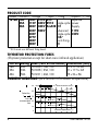
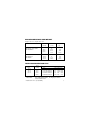
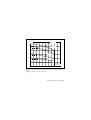
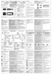
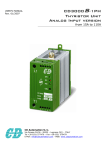
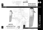
Thyristor Power Controller
TE10A
Burst-Firing
UL
74B5
C
UL
LISTED
INDUSTRIAL CONTROL EQUIPMENT
User Manual
TE10ABurst Iss 2/MO.Correc
6/11/00
9:34
Page 2
TE10A
Industrial thyristor power controller
Burst-firing, Single-cycle or advanced Single-cycle
CONTENTS
SAFETY DURING INSTALLATION AND USE . . . . . . . . . 3
EUROPEAN DIRECTIVES . . . . . . . . . . . . . . . . . . . . . . . . . . 4
TECHNICAL SPECIFICATION . . . . . . . . . . . . . . . . . . . . . . 6
PRODUCT CODE. . . . . . . . . . . . . . . . . . . . . . . . . . . . . . . . . . 8
FUSES . . . . . . . . . . . . . . . . . . . . . . . . . . . . . . . . . . . . . . . . . . . 8
CURRENT DERATING (as a function of ambient
temperature). . . . . . . . . . . . . . . . . . . . . . . . . . . . . . . . . . . . . . . 8
INSTALLATION AND DIMENSIONAL DETAILS . . . . . . . 9
FRONT FACIA . . . . . . . . . . . . . . . . . . . . . . . . . . . . . . . . . . . 10
TERMINALS AND CONNECTORS . . . . . . . . . . . . . . . . . . 11
WIRING . . . . . . . . . . . . . . . . . . . . . . . . . . . . . . . . . . . . . . . . 12
Control of TE10A by temperature controller . . . . . . . . . . . . 12
Local control by potentiometer . . . . . . . . . . . . . . . . . . . . . . . 13
Local control by contacts. . . . . . . . . . . . . . . . . . . . . . . . . . . . 13
Auxiliary power supply (option) . . . . . . . . . . . . . . . . . . . . . . 14
INPUT SIGNAL . . . . . . . . . . . . . . . . . . . . . . . . . . . . . . . . . . 15
FIRING MODES . . . . . . . . . . . . . . . . . . . . . . . . . . . . . . . . . . 16
Burst firing. . . . . . . . . . . . . . . . . . . . . . . . . . . . . . . . . . . . . . . 16
Single-cycle . . . . . . . . . . . . . . . . . . . . . . . . . . . . . . . . . . . . . . 17
Advanced Single-cycle . . . . . . . . . . . . . . . . . . . . . . . . . . . . . 18
CONFIGURATION OF FIRING MODE . . . . . . . . . . . . . . . 19
Burst firing and standard Single-cycle (codes FC and FC1) . 19
Advanced Single-cycle (code SCA) . . . . . . . . . . . . . . . . . . . 20
For any further information, or if in doubt, please contact Eurotherm Controls
wh e re qualified staff are ava i l able to advise or assist you with the
commissioning of your installation.
2
User manual TE10A
TE10ABurst Iss 2/MO.Correc
6/11/00
9:34
Page 3
SAFETY DURING INSTALLATION AND USE
This symbol means that failure to take note of the
information given in this manual may have serious
consequences for the safety of personnel and may even
result in electrocution.
DANGER!
• Units must be installed in fan-cooled electrical cabinets to ensure that
condensation and pollution are excluded. The cabinet must be closed and
bonded to the safety earth in accordance with Standards NFC15-100,
IEC 364 or current national Standards. It is the responsibility of the user to
install and wire the installation in accordance with current professional
practice.
• Before any connection or disconnection, make sure that power and control
cables and leads are isolated from voltage sources.
• The safety earth must be connected before any other connection is made
during wiring and should be the last cable to be disconnected.
• Thyristors are not isolating devices.
The high-speed fuse recommended is used only to protect the thyristors:
under no circumstances can it be used to protect the installation. For this
reason it is very important to fit a suitable device guaranteeing protection
for, and electrical isolation of, the installation in compliance with current
practice.
• Access to the internal components of the product is prohibited to users
Disconnect the TE10A completely before dismantling.
• The temperature of the heatsink fins may exceed 100°C.
Avoid all contact, even occasional, with the heatsink while the TE10A is
operational.
The heatsink remains hot for approximately 15mins after the TE10A has
been switched off.
User manual TE10A
3
TE10ABurst Iss 2/MO.Correc
6/11/00
9:34
Page 4
EUROPEAN DIRECTIVES
CE MARKING
TE10A products carry the CE mark in compliance with the essential
requirements of the Low Voltage Directive 73/23EC of 19/2/73 (amended by
the Directive 93/68/EC of 22/7/93).
For safety reasons, TE10A products installed and used in compliance with this
user manual meet the essential requirements of the European Directives
mentioned above.
CE DECLARATION OF CONFORMITY
A CE Declaration of conformity is available on request.
ELECTROMAGNETIC COMPATIBILITY (EMC)
(For an industrial environment only, must not be used in domestic
environments)
Eurotherm certifies that TE10A Burst firing and Single Cycle fired products,
installed and used in compliance with their manual, meet the following EMC
standards and enable the system which incorporates them to comply with the
EMC Directive as far as those TE10A products are concerned.
EMC STANDARDS
Immunity
Generic standard : EN 50082-2
Test standards
Emission
4
: EN 61000-4-2, EN 61000-4-4,EN 61000-4-5
ENV 50140, ENV 50141, ENV 50204
Generic standard : EN 50081-2
Test standard
: EN 55011
Product standard : IEC 1800-3
User manual TE10A
TE10ABurst Iss 2/MO.Correc
6/11/00
9:34
Page 5
INTERNAL EMC FILTER
An EMC filter is incorporated into the Burst firing and Single Cycle firing
TE10A to reduce conducted emission in accordance with the EMC Directive.
VALIDATION BY INDEPENDENT BODY
Eurotherm has validated the compliance of these TE10A controllers with the
Low Voltage Directive mentioned above and with EMC standards through
product design and laboratory testing.
The controls carried out on TE10A products are listed in a Technical
Construction File validated by the LCIE (Central Laboratory for the Electrical
Industries), a Recognised Competent Body.
PRECAUTIONS
Before installation, please read this manual thoroughly.
Eurotherm cannot be held responsible for any damage to persons or property,
or for any financial loss or costs arising from incorrect use of the product or
failure to observe the instructions given in this manual.
PERSONNEL
The installation, configuration, commissioning and maintenance of the power
unit should only be carried out by personnel qualified and trained to work
with low voltage electrical equipment in an industrial environment.
INDEPENDENT SAFETY DEVICE
Given the value of the equipment controlled by TE10A, it is the responsibility
of the user, and it is highly recommended, that an independent safety device
(alarm) should be installed. This alarm must be tested regularly. Eurotherm
can supply suitable equipment.
'ELECTROMAGNETIC COMPATIBILITY' INSTALLATION GUIDE
In order to help you reduce the effects of electromagnetic interference
depending on the product installation, Eurotherm can supply you with the
'Electromagnetic Compatibility' Installation Guide (ref. HA025464).
User manual TE10A
5
TE10ABurst Iss 2/MO.Correc
6/11/00
9:34
Page 6
TECHNICAL SPECIFICATION
Power
Nominal current at 45°C
Nominal voltage
Supply frequency
Current in ‘off state’
Regulation
Type of regulation
Linearity
Stability
Firing modes
Firing indicator
Control Inputs
External signal type
Input impedance
Local control
CE marking
Electrical safety
6
16, 25 or 40A.
100Vac to 500Vac +10%, -15%
50 or 60Hz (nominal) ±2Hz
Below 30mA typically
The load power is proportional to the control input
Better than ±2% of the full range
Automatic compensation for supply variations
from ±10% of the nominal voltage. Stability
better than ± 2% of the full range on constant
resistance
Thyristor firing at zero voltage
• Burst mode: firing and non-firing over a
whole number of mains cycles
• Single-cycle: firing or non-firing for one mains
cycle
• Advanced Single-cycle: firing over a whole
number of mains cycles, non-firing over a whole
number of half cycles
Green LED on front facia
Analogue, DC voltage or current:
0 - 5V, 0 - 10V or 4 - 20mA
Voltage 100KΩ, current 250Ω
External potentiometer 10k
'Dry' contact: logic operation - 'all or nothing'
A '5V user' voltage is available
The CE Mark in accordance with the Low
Voltage Directive 73/23/EC amended by the
Directive 93/68/EC of 22/7/93
User manual TE10A
TE10ABurst Iss 2/MO.Correc
EMC
Environment
Operating temperature
Operating atmosphere
Humidity
Pollution
Thyristor protection
Protection degree
Insulation (1 minute test)
Cooling
Mounting
Option
Auxiliary power supply
Wiring
Guarantee
6/11/00
9:34
Page 7
These TE10A products comply with
Electromagnetic Compatibility test standards
(see page 4)
0 to 60°C, (see derating curves) at maximum
altitude of 2000m
Storage: -10 to +70°C
Non-conductive, non-explosive and noncorrosive
RH: 5 to 95%, non-condensing
Pollution degree 2 permissible (IEC 664)
External fuse, internal MOV (varistor) and
RC snubber
IP20 (in accordance with IEC 529; ¶11.4,
table 5)
Isolation distances according to IEC 664
2000Vac between power and earth
3600Vac between power and control inputs
Natural convection
Vertical on DIN rail
115Vac or 230Vac used in the case of nonstandard mains or if independent power
supply required
The separate auxiliary power supply must be in
phase or anti-phase with the load supply
Two years for parts and labour (return to
factory)
In order to maintain its ‘leading edge’ Eurotherm may have to make changes to its
specifications without advance notice. For any further information, or if in doubt, please
contact Eurotherm Controls.
User manual TE10A
7
PRODUCT CODE
Model / Current / Voltage
/ Input / Firing
/Option / 00
TE10A 16A
100V 415V 0V5
Separate
25A
115V 440V 0V10 Single-cycle: power
40A
200V 480V 4mA20 FC1
Supply
230V 500V
Advanced
115V
240V
Single-cycle: 230V
277V
SCA*
380V
Burst-firing:
400V
FC
* SCA mode uses different firing board
THYRISTOR PROTECTION FUSES
(Thyristor protection except for short-wave infrared application)
Current
16A
25A
40A
Rating
20A
32A
50A
Code (Fuse & fuse-holder)
FU1038 / 16A / 00
FU1038 / 25A / 00
FU1451 / 40A / 00
Dimensions (mm)
81 x 17.5 x 68
81 x 17.5 x 68
95 x 26 x 86
CURRENT DERATING (as a function of ambient temperature)
50 I eff (A)
I N : nominal current at 45°C
I N = 40 A
40
Dotted line
(
): 30
limit of
recommended 20
fuse
I N = 25 A
I N = 16 A
10
Ambient temperature (°C)
0
20
8
25
30
35
40
45
50
55
60
User manual TE10A
TE10ABurst Iss 2/MO.Correc
6/11/00
9:35
Page 9
INSTALLATION AND DIMENSIONAL DETAILS
Minimum spacing between 2 TE10A units:
10mm up to 45°C
17·5mm over 45°C
Dimensions
(in mm)
DIN rail clip mounting
(EN 50022-35 x 7·5 and 35 x 15)
Ground continuity: For reasons of electromagnetic compatibility
ensure that the metal DIN rail of the TE10A installation is
electrically bonded to the reference ground (panel or bulkhead).
User manual TE10A
9
TE10ABurst Iss 2/MO.Correc
6/11/00
9:35
Page 10
FRONT FACIA
10
User manual TE10A
TE10ABurst Iss 2/MO.Correc
6/11/00
9:35
Page 11
TERMINALS AND CONNECTORS
Power terminal block: cage terminals for 1.5 to 16mm2 cables, strip
insulation by 16 mm, tightening torque 1.2 Nm.
Safety earth wiring: same section as power conductor, tightening
torque 2 Nm.
Control connection to terminals 5 & 6, and separate auxiliary power
supply connection (option) to terminals 8 & 10: use 0.5 to 1.5 mm2
wire, strip insulation by 7 mm, tightening torque 0.4 Nm (0.25 Nm
for terminals 8 & 10).
View from below
User manual TE10A
11
TE10ABurst Iss 2/MO.Correc
6/11/00
9:35
Page 12
WIRING
Control of TE10A by temperature controller
L
N
Line protection
circuit breaker
(installed by user)
Thyristor
protection fuse
1A
fuse
Controlled
phase
Neutral
1
Temperature controller
EUROTHERM
2216
Firing
indicator
2
3
4
- + 5V
V+
3
V-
Thermocouple
input
1
ON
TE10A 5 6 7
Analogue
output
ε
EUROTHERM
L
N
E
1A 1B
2
Analogue
input
5 6 7
+
Load
0V
4
Safety
earth
Example of wiring for TE10A (240V nominal, input 0 to 10V)
controlled by Eurotherm 2000 series temperature controller.
12
User manual TE10A
TE10ABurst Iss 2/MO.Correc
6/11/00
9:35
Page 13
Local control by potentiometer
The input must be configured as 0 to 5V (code 0V5).
Local control by contacts
The input must be configured as 0 to 5V (code 0V5).
User manual TE10A
13
TE10ABurst Iss 2/MO.Correc
6/11/00
9:35
Page 14
Auxiliary power supply (option)
Use of TE10A with non-standard mains.
Example of separate auxiliary power supply wiring (option).
The auxiliary power supply must be in phase or in anti-phase with
the load supply.
14
User manual TE10A
TE10ABurst Iss 2/MO.Correc
6/11/00
9:35
Page 16
FIRING MODES
Three firing modes are possible:
Burst firing, Single-cycle and advanced Single-cycle.
Thyristor firing and quenching occurs at zero voltage which
minimises interference to the supply network.
Burst firing
Burst firing mode consists of supplying a series of whole mains
cycles to the load.
The load power is proportional to the ratio of the firing time (TF) to
the modulation time (TM). The OFF time (TNF) is also a series of
whole mains cycles.
TM = TF + TNF
The period of modulation is variable according to the output power
demand.
• At 50% of nominal power the thyristors are on for 300ms ±100ms
and are off for 300ms ±100ms (at 50 Hz)
• For a setpoint less than 50%, the non-firing period increases, and
the firing period is fixed (300ms ±100ms)
• For a setpoint greater than 50%, the firing period increases, and
it is the non-firing period which is fixed (300ms ±100ms)
16
User manual TE10A
TE10ABurst Iss 2/MO.Correc
6/11/00
9:35
Page 17
Single-cycle
The mode of firing with only one firing or non-firing mains cycle is
called Single-cycle.
• At 50% of nominal power the thyristors are on for 20ms and are
off for 20ms (at 50Hz)
• For a setpoint less than 50% the non-firing period increases and
the firing period is fixed at 20ms
• For a setpoint greater than 50% the firing period increases and it is
the non-firing period which is fixed at 20ms.
User manual TE10A
17
TE10ABurst Iss 2/MO.Correc
6/11/00
9:35
Page 18
Advanced Single-cycle (Uses different board)
In order to minimise power fluctuation during the modulation period,
the advanced Single-cycle mode uses half-cycles for non-firing.
Examples of firing in Single-cycle (a) and in advanced Single-cycle
(b) modes at 66.6% of nominal power.
• For a setpoint less than 50%, firing is effected on mains halfcycles. The firing time is fixed at one cycle (20ms at 50Hz)
• For a setpoint greater than 50%, non-firing is reduced to one halfcycle. Firing is effected over whole cycles.
The use of half-cycles for non-firing is the reason for the reduction in
flicker and brightness of infrared elements compared with Singlecycle.
18
User manual TE10A
Solid State Contactors TE10S
Power Controllers TE10A
ε
EUROTHERM
ADDENDUM
TE10S User Manual Part N°:
HA174780ENG, HA174782ENG,
HA174784ENG, HA175436ENG
TE10A User Manual Part N°:
HA175247ENG, HA175548ENG
NOMINAL CURRENT UP TO 50 A
and
SHORT WAVE INFRARED APPLICATIONS
© Copyright Eurotherm Automation S.A. 1997
All rights strictly reserved. No part of this document may be
stored in a retrieval system, or any form or by any means
without prior written permission from Eurotherm Automation
SA.
Part N°. HA175600 ENG - Issue 2.0 - 12/98
TECHNICAL SPECIFICATION
MAXIMUM CURRENT
In order to take into account supply voltage variations and
heating element resistance dispersion (all types of heating
elements including short wave infrared), a 0.8 safety coefficient
must be used on the thyristor unit current rating to determine the
maximum value of the load nominal current which the unit can
safely control.
SHORT WAVE INFRARED (SWIR) APPLICATIONS
Applications using short wave infrared heaters in Single Cycle,
Fast Cycle or Advanced Single Cycle are reserved to 16 A, 25 A
and 40 A current rating.
With a safety coefficient of 0.8 the maximum current for SWIR
which can be controlled is:
TE10 rating
16 A
25 A
40 A and 50 A
2
SWIR maximum
controlled current
13 A
20 A
32 A
Addendum TE10 (50A/SWIR)
RANGE DIMENSIONS AND WEIGHT
Height 115 mm / Depth 92.5 mm
Nominal
current
Width
(mm)
TE10S/DC, TE10S/AC
TE10S/PDSIO
16 A
25 A
40 A
50 A
35
52.5
87.5
105
350
500
850
1100
TE10S/PLF
TE10A/Burst
TE10A/PA
16 A
25 A
40 A
50 A
52.5
70
105
122.5
550
700
900
1200
Models
Weight
(g)
THYRISTOR PROTECTION FUSE
TE10
rating
16 A
25 A
40 A
50 A
Attention!
Fuse
rating
Code
Dimensions(mm)
20 A
32 A
50 A
63 A
FU1038/16A/00
FU1038/25A/00
FU1451/40A/00
FU2258/50A/00
81 x 17.5 x 68
81 x 17.5 x 68
95 x 26 x 86
140 x 35 x 90
Fuse & fuse-holder
For SWIR applications, the high-speed fuse
must not be used
Addendum TE10 (50A/SWIR)
3
IRMS (A)
60
IN = 50 A
50
IN = 40 A
40
30
IN = 25 A
20
IN = 16 A
10
Operation
tempereature (°C)
0
20
25
30
35
40
45
50
55
60
65
70
Current derating as a fonction of ambient temperature (IN = nominal current at
45°C)
Dotted line : limit due to recommended fuse
4
Addendum TE10 (50A/SWIR)
Eurotherm: International sales and service
BELGIUM & LUXEMBOURG Moha
T (+32) 85 274080
E [email protected]
Guangzhou Office
T (+86 20) 8755 5099
E [email protected]
Beijing Office
T (+86 10) 6567 8506
E [email protected]
Shanghai Office
T (+86 21) 6145 1188
E [email protected]
DENMARK Copenhagen
T (+45 70) 234670
E [email protected]
IRELAND Dublin
T (+353 1) 4691800
E [email protected]
AUSTRALIA Sydney
T (+61 2) 9838 0099
E [email protected]
AUSTRIA Vienna
T (+43 1) 7987601
E [email protected]
BRAZIL Campinas-SP
T (+5519) 3707 5333
E [email protected]
FINLAND Abo
T (+358) 22506030
E [email protected]
FRANCE Lyon
T (+33 478) 664500
E [email protected]
GERMANY Limburg
T (+49 6431) 2980
E [email protected]
HONG KONG & CHINA
T (+85 2) 28733826
E [email protected]
INDIA Chennai
T (+91 44) 24961129
E [email protected]
ITALY Como
T (+39 031) 975111
E [email protected]
KOREA Seoul
T (+82 31) 2738507
E [email protected]
NETHERLANDS Alphen a/d Rijn
T (+31 172) 411752
E [email protected]
NORWAY Oslo
T (+47 67) 592170
E [email protected]
Equipment made in a certified ISO9001 factory.
© Copyright Eurotherm Automation SAS 1996
All rights reserved.
User Manual TE10A/BUR - HA175247ENG
POLAND Katowice
T (+48 32) 2185100
E [email protected]
SPAIN Madrid
T (+34 91) 6616001
E [email protected]
SWEDEN Malmo
T (+46 40) 384500
E [email protected]
SWITZERLAND Wollerau
T (+41 44) 7871040
E [email protected]
UNITED KINGDOM Worthing
T (+44 1903) 268500
E [email protected]
www.eurotherm.co.uk
U.S.A. Leesburg VA
T (+1 703) 443 0000
E [email protected]
www.eurotherm.com