1
MasterCase
User manual
We wish to save you time and money!
We can assure you that the thorough reading of this manual will guarantee correct installation and
safe use of the product described.
BEFORE INSTALLING OR HANDLING THE DEVICE PLEASE CAREFULLY READ AND FOLLOW THE
INSTRUCTIONS DESCRIBED IN THIS MANUAL.
This device has been manufactured to operate risk-free for its specific purpose, as long as:
it is installed, operated and maintained according to the instructions contained in this manual;
the environmental conditions and the voltage of the power supply correspond to those specified.
All other uses and modifications made to the device that are not authorised by the manufacturer are considered incorrect.
Liability for injury or damage caused by the incorrect use of the device lies exclusively with the user.
Please note that this unit contains powered electrical devices and therefore all service and maintenance operations must be
performed by specialist and qualified personnel who are aware of the necessary precautions.
Disconnect the machine from the mains power supply before accessing any internal parts.
Disposal of the parts of the controller:
The controller is made up of metal and plastic parts and contains a lithium battery. All these parts must be disposed of
according to the local standards in force.
General warnings - operating environments and connections
The following conditions represent correct installation:
1. do not install the instrument in environments with the following characteristics: wide and rapid fluctuations in ambient
temperature; temperature and relative over the allowed limit; exposure to direct pressurised jets of water; high levels of
magnetic and/or radio frequency interference (e.g. from transmitting antennae);
2. use cable ends suitable for the corresponding terminals. Loosen each screw and insert the cable ends, then tighten the screws.
When the operation is completed, slightly tug the cables to check that they are sufficiently tight;
3. separate as much as possible the signal cables from the cables carrying inductive loads and power cables to avoid possible
electromagnetic disturbance. Never insert power cables (including the electrical cables) and probe signal cables in the same
conduits. Do not install the probe cables in the immediate vicinity of power devices (contactors, circuit breakers or similar);
4. reduce the path of the probe cables as much as possible, and avoid spiral paths that enclose power devices. To extend the
probe cables, use cables with a minimum cross-section of at least 0.5mm2;
5. the cables connected to the contacts on the controller must be rated for the maximum operating temperature, determined by
considering the maximum room temperature envisaged, added to the heating up of the controller itself, equal to 20°C;
6. suitably protect the load power lines on the controller with devices (circuit breakers) rated according to the loads connected.
Safety for operators and precautions when handling the controller
To protect the safety of operators and safeguard the controller, before doing any work on the panel always disconnect the power
supply. Electrical damage may occur to the electronic components as a result of electrostatic discharges from the operator.
Suitable precautions must be therefore be taken when handling these components, specifically:
• before handling any controller, earth yourself (not touching the board does not prevent a spike, as a 10000V discharge, easily
reached with static electricity, can produce an arc of about 1cm);
• all materials must be kept inside their original package as long as possible. If necessary, take the controller from its package
and place it into an antistatic package without touching the rest of the controller with your hands;
• absolutely avoid non-antistatic plastic bags, polystyrene or sponges;
• do not pass the controller directly to other operators (to prevent from electrostatic induction and discharges).
CONTENTS
1.
2.
3.
4.
5.
General characteristics ..................................................................................................................................................................... 3
1.1
Main characteristics of MasterCase.............................................................................................................................................. 3
Layout of the hardware..................................................................................................................................................................... 5
2.1
Meaning of the inputs and outputs................................................................................................................................................ 5
2.2
Codes of the models and accessories............................................................................................................................................ 8
2.3
User interface ............................................................................................................................................................................... 9
Installation ....................................................................................................................................................................................... 11
3.1
Electrical connections................................................................................................................................................................. 11
3.2
Configuration of the controllers ................................................................................................................................................. 11
LAN functions.................................................................................................................................................................................. 14
4.1
Network defrost in multiplexed installations.............................................................................................................................. 14
4.2
Remote alarm signals. ................................................................................................................................................................ 14
4.3
Transmission of control signals and probe readings................................................................................................................... 14
Setting the parameters .................................................................................................................................................................... 15
5.1
Classification of the parameters ................................................................................................................................................. 16
5.2
"Password" parameters............................................................................................................................................................... 16
5.3
/= temperature probe management parameters ........................................................................................................................... 18
5.4
r= temperature control parameters.............................................................................................................................................. 20
5.5
c= times and safety parameters ..................................................................................................................................................... 21
5.6
d= defrost management parameters ............................................................................................................................................ 23
5.7
A= alarm management parameters ............................................................................................................................................. 27
5.8
F= evaporator fan management parameters................................................................................................................................ 30
5.9
H= other settings ........................................................................................................................................................................ 31
5.10 LAN parameters ......................................................................................................................................................................... 33
5.11 "set point" parameters................................................................................................................................................................. 33
5.12 t= HACCP parameters................................................................................................................................................................ 35
5.13 RTC (Real Time Clock) parameters ........................................................................................................................................... 37
5.14 P= electronic valve (EEV) option (code MGE0000020) ............................................................................................................ 38
6.
7.
Table of parameters ........................................................................................................................................................................ 44
Alarms .............................................................................................................................................................................................. 49
7.1
Anomalous or special operation ................................................................................................................................................. 49
7.2
Description of the signals and alarm codes shown on the display .............................................................................................. 50
8.
Technical specifications................................................................................................................................................................... 53
MasterCase
1. General characteristics
MasterCase is the integrated system designed by Carel for the complete management of showcases.
MasterCase controls and manages the entire refrigeration unit, both electrically and electronically.
The use of power relays means that MasterCase does not require an extra electrical panel, and can directly control the lights,
defrost heaters, fans, cooling actuators, and so on.
MasterCase can be connected to a local network to coordinate operations on a group of utilities, synchronising defrosts or sharing
probes.
Furthermore, MasterCase can be integrated into the PlantVisor system, which saves and displays all the data on the operation of
the unit.
MasterCase is available for the control of showcases with both mechanical expansion valves and in the version with "built-in" driver
for the management of proportional electronic expansion valves, which maximises the performance of the refrigeration unit.
The electronic valve optimises the evaporation temperature and superheating, and reduces the power consumption of the unit.
Product conservation quality and lower weight loss are ensured by the greater temperature stability and the reduced need for
defrosts using MasterCase.
1.1 Main characteristics of MasterCase
Power supply
230V alternating current
Appearance and assembly
The dark plastic container, the narrow, stretched shaped, and the rear supports for DIN rail mounting, make MasterCase ideal for
supermarkets and for installation under the showcase.
In addition, the 220Vac power supply and the relay outputs with voltage signals for the various loads (lights, fans, defrost, etc....)
mean significant time savings for the wiring and assembly of the electrical panel, the controller itself featuring an integrated
electrical panel.
User interface
The user interface is from the series of standard PST terminals. This series, as well as being the same used by other Carel
instruments (meaning a reduction in the number of product codes), offers various solutions: display only, small terminal with 3
digits and 3 buttons, and large terminal with 4 digits and 8 buttons. Each button is backlit by a LED to signal the status of the unit
(actuators on, alarms, etc...).
The terminals are not required for the operation of the MasterCase, but rather are used to program the controller. The terminals
can be installed at a distance of up to 10m from the instrument, and can be connected "live", that is, when the instrument is on,
without creating problems in operation.
Energy Savings - Advanced Software
Thanks to the numerous and innovative functions featured, the MasterCase not only controls all the various configurations of the
showcases, but also ensures considerable advantages in terms of energy savings. In fact, the use of the night-time set point, the
possibility of different types of intelligent defrosts, and the control of electronic expansion valves are just some of the functions
that allow significant energy savings to be achieved.
Local network (LAN)
The MasterCase instruments can be connected together to create a LAN (Local Area Network), in master-slave configuration, for
the control of multiplexed showcases or multi-evaporator utilities.
Each instrument can be configured as either the master or a slave by simply setting a parameter.
This configuration allows the synchronisation and coordination of defrosts, the signalling of the status of the digital inputs, as
well as the display on the master of any alarms active on the slaves.
Up to 6 instruments (1 master and 5 slaves) can be connected together.
The particularly reliable structure of the LAN (16-bit CRC error checking) means the values read by the control temperature
and/or pressure probe on the master can be shared across the network, thus allowing a saving in the number of probes required.
Finally, as regards the supervision software, the master acts as the interface for the slaves, as only the master needs to be fitted
with the serial card and connected to the RS485 line to be able to manage all the instruments in the local network.
Alarm log
Each unit can save up to 10 alarms. Each new alarm is recorded in the log, deleting the oldest event if necessary.
RTC
The MasterCase can be fitted with an RTC card (with backup battery) for managing the defrosts at set times. In addition, this
option allows the use of other functions, such as the setting of a night-time set point starting and ending at set times, the saving of
the age of the event in the alarm log, and so on.
Carel code +030220221 Rel. 1.1 dated 18/11/04
3
MasterCase
Third probe
This is used to measure the temperature at the hot point of the showcase and is used to help determine the reference control
temperature. In addition, it can be used to manage the defrost function on a second evaporator.
Duty Cycle setting
This function allows the utility to be operated even when there is a control probe fault. In these cases, operation will continue for
a time (in minutes) equal to the value set for the parameter "duty setting" (c4), with a fixed off time of 15 minutes.
Multifunction output
The auxiliary outputs (AUX1 and AUX2) are programmable and can duplicate the function of any of the outputs already present.
In addition, they can be used as alarm outputs or hot wire outputs, and can be configured as additional defrost outputs that are
independent of the standard defrost output, associated with probe 3..
Multifunction input
A total of five programmable digital inputs are available (see the list of parameters). These allow numerous possibilities, such as
the enabling of defrosts, the management of immediate or delayed alarms, the control of a door switch, etc.... In addition, a digital
input known as the "virtual" input can be configured, which is not physically connected but rather managed via the local network.
Continuous cycle
The continuous cycle function allows the utility controlled to be forced on for a time set by parameter. This function may be
useful when requiring a rapid reduction in temperature, even below the set point.
In-circuit testing
The MasterCase series is manufactured using the most advanced SMD technology. All the controllers undergo "in-circuit testing"
to check the components installed..
Probes
The instruments are designed to operate with NTC probes, which offer greater precision across the rated operating range. The
pressure probes used are ratiometric. All the probes can be supplied by CAREL.
Electronic valve
An optional card soldered directly onto the main board of the MasterCase (version MGE0000020) can be used to control the
operation of an electronic expansion valve with stepper motor. This allows the possibility to directly control the injection of
refrigerant into the evaporator. Consequently, lower and more stable superheating values can be achieved, as well as a higher
evaporation temperature and consequently higher humidity and a more constant temperature in the showcase, guaranteeing better
conservation and quality of the products.
Watchdog (Surveillance)
This device prevents the microprocessor from losing control of the unit even in the presence of significant electromagnetic
disturbance. In the event of abnormal operation, the watchdog re-establishes the initial operating status.
Electromagnetic compatibility
The instruments comply with the EU standards on electromagnetic compatibility.
CE mark and ISO 9001 certification
The quality and the safety of the MasterCase series instruments are guaranteed by CAREL's ISO 9001 certified design and
production system, and by the CE mark on the product.
Carel code +030220221 Rel. 1.1 dated 18/11/04
4
MasterCase
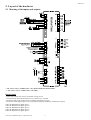
2. Layout of the hardware
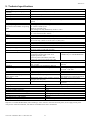
2.1 Meaning of the inputs and outputs
*: The colours refer to CAREL cables, codes PSTCON0300 and PSTCON1000
**: The colours refer to CAREL cables, code SPKC*
Digital inputs
- inputs from voltage-free contacts, with 8mA closing current;
- connection with removable terminals for wires from 0.25 to 2.5mm2;
- maximum length of the cables 30m for standards compatibility (surge);
- the function of the digital inputs can be programmed using the parameters (multifunction inputs);
G-DI1 ! Multifunction digital input 1;
G-DI2 ! Multifunction digital input 2;
G-DI3 ! Multifunction digital input 3;
G-DI4 ! Multifunction digital input 4;
G-DI5 ! Multifunction digital input 5.
Carel code +030220221 Rel. 1.1 dated 18/11/04
5
MasterCase
Temperature probe inputs (NTC sensors)
- inputs for standard Carel NTC probes (10 kΩ at 25 °C);
- connection with removable terminals for wires from 0.25 to 2.5mm2;
- maximum length of the cables 30m.
G-S1 ! Room probe (S1);
G-S2 ! End defrost probe (S2);
G-S3 ! Third probe (S3);
G-S4 ! Not used.
P.C. (Condensing pressure)
" Featured but currently not managed
Fan output
L ! Line
N ! Neutral
4A 250Vac (Inductive Load)
Light
L ! Line
N ! Neutral
1000VA 250Vac (Fluorescent Lamp)
Compressor
L ! Line
N ! Neutral
12(12)A 2 Hp, 250Vac (Inductive Load)
Defrost
L ! Line
N ! Neutral
12A 250Vac (Resistive Load)
230Vac
- Power supply input from mains to two removable screw terminals, with max 12A current rating
- minimum recommended cross-section of the wires from 1.5 to 2.5mm2.
L ! Line
N ! Neutral
230Vac +10/-15% 50/60 Hz
230Vac +10/-15% 50/60 Hz
Alarm output
C ! Common
N.O. ! Normally open (voltage-free contact)
N.C. ! Normally closed
12 A 250Vac (Resistive Load)
Auxiliary output (AUX2)
L ! Line
N ! Neutral
Carel code +030220221 Rel. 1.1 dated 18/11/04
12A 250Vac (Resistive Load)
6
MasterCase
AUX Auxiliary output (AUX1)
L ! Line
N ! Neutral
12A 250Vac (Resistive Load)
Note for all the outputs:
removable screw terminals for cables with cross-section from 0.25 to 2.25 mm2.
Electronic expansion valve
maximum length of the cables 10m;
1 GREEN
W1
3 RED
4 WHITE
W2
2 BLACK
Valve Motor
External backup battery
" Featured but currently not managed
24Vac
20VA, 0.5A transformer;
~ ! At the transformer 24Vac output
~ ! At the transformer 24Vac output
Superheated gas temperature probe (NTC Sh)
Models for electronic valve only (code MGE0000020).
G-Tsh ! NTC temperature probe for superheated gas (evaporator outlet)
P.E. (Evaporation pressure)
Models for electronic valve only (code MGE0000020).
for distances greater than 10m use shielded cable (2 wires plus shield connected to earth);
G ! Earth (green)**
P ! Signal (white)**
Vp ! Power supply (black)**
**: The colours refer to CAREL cables, code SPKC*
RS485 driver
" Featured but currently not managed
PWM
" Featured but currently not managed
Serial line connection (Supervisor)
- Connector for optional RS485 board to interface with supervisor;
- removable screw terminals for cables with cross-section from 0.25 to 2.25 mm2;
- serial speed envisaged 19200 bit/s;
G ! Earth
T+ ! Connection to the positive of the RS485 serial line
T- ! Connection to the negative of the RS485 serial line
Carel code +030220221 Rel. 1.1 dated 18/11/04
7
MasterCase
Terminals (Interface Display)
- three-wire serial connection, maximum length 10m
- power supply from the controller 24/35Vdc, 1.5 W max.
Vs ! Power supply (Power – green)*
T+ ! Signal (Tx/Rx – white)*
G ! Earth (GND – red/brown and yellow)*
*: The colours refer to CAREL cables, codes PSTCON0300 and PSTCON1000
LAN (Local Area Network)
- local network connection to other controllers, max length 10m;
- removable screw terminals for wires with cross-section from 0.25 to 2.25mm2.
T+ ! Signal
G ! Earth
PROGRAMMING KEY
The programming key should only be used when the controller is disconnected from the power supply (220Vac terminals not
live), and with the valve driver card powered (in models code MGE0000020 - 24Vac power supply terminals).
The product code of the programming key is PSOPZKEY00.
For details on how to use the key refer to the corresponding instruction sheet.
2.2 Codes of the models and accessories
CONTROLLERS
CODE
DESCRIPTION
MGE0000010
MasterCase "basic" for showcases with TXV
MGE0000020
MasterCase with EXV driver option
OPTIONS AND ACCESSORIES
CODE
MGEOPZSER0
MGEOPZCLK0
MGECON0010
MGECON0020
PSOPZKEY00
PSOPZKEYA0
DESCRIPTION
Serial board
Clock board
Removable connector kit for MasterCase "basic"
Removable connector kit for MasterCase EXV
Hardware programming key
Hardware programming key with external 230 Vac power supply
USER INTERFACE
CODE
PST00LR200
PST00SR300
PST00VR100
PSTCON0300
PSTCON1000
Carel code +030220221 Rel. 1.1 dated 18/11/04
DESCRIPTION
Large terminal, 8 buttons with red display, IR receiver, buzzer
Small terminal, 3 buttons with red display, IR receiver, buzzer, 1 input for
NTC probes, 2 digital inputs
Red display, 1 input for NTC probes
3m connection cable
10m connection cable
8
MasterCase
2.3 User interface
The MasterCase uses the series of standard PST terminals as the user interface.
This series, as well as being the same used by other Carel instruments (consequently allowing a reduction in product codes),
offers various solutions:
- small terminal with 3 digits and 3 buttons (code PST00SR300);
- large terminal with 4 digits and 8 buttons (code PST00LR200);
- remote display with 3 digits (code PST00VR100).
Important: the remote display will only work if one of the two terminals is also connected.
Each button is backlit by a LED to signal the status of the unit (outputs active, alarms, etc...).
The terminals are not required for the operation of the MasterCase, but rather are used to program the controller. The terminals
can be connected "live", that is, when the instrument is on, without creating problems in operation.
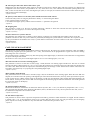
2.3.1 Functions of the buttons and LEDs on the PJ Large terminal (PST00LR200)
2
4
6
1
8
3
5
7
Button # (red LED)
Normal operation
• pressed for 5 seconds eliminates the HACCP alarm and its signals (codes "HA" or "HF" on the display, the buzzer and the alarm
relay) and in addition deletes all the corresponding data saved.
LED
on steady: HACCP alarm.
Button $ (yellow LED)
Normal operation
• Pressed for 1 second activates /deactivates the AUX1 output relay (light)
LED
• on steady: AUX1 output relay (light) active.
Button % (green LED)
Normal operation
• Pressed for 5 seconds unit ON/OFF.
LED
• On steady: controller on.
Note: the ON/OFF function depends on an enabling parameter (if not enabled, the controller is always ON), the LED in any case
displays the status.
Button & (yellow LED)
No function associated.
Button ' (green LED)
Normal operation
• Pressed for 5 seconds activates or deactivates the continuous cycle.
LED
• on steady: continuous cycle on.
Button ( (green LED)
Normal operation
• Pressed for 1 second switches the light on/off;
• pressed together with button 8 displays the value of the third probe (S3);
• pressed together with button 7 for 5 seconds activates or deactivates the continuous cycle.
Parameter programming
• Passes from one parameter to the next;
• increases the value of the parameter displayed.
LED
• On steady: compressor on;
• Flashing: compressor activation request in progress (cooling request).
Carel code +030220221 Rel. 1.1 dated 18/11/04
9
MasterCase
Button ) (yellow LED)
Normal operation
• Pressed for 5 seconds starts a manual defrost, if the conditions are right;
• pressed together with button 6 for 5 seconds activates or deactivates the continuous cycle;
• pressed together with button 8 displays the value read by the end defrost probe (S2);
• pressed on controller power-up together with button 8 loads the default parameters.
Parameter programming
• Passes from one parameter to the previous;
• decreases the value of the parameter displayed.
LED
• on steady: defrost on;
• flashing: defrost request in progress.
Button * (red LED)
Normal operation
• Mutes the audible alarm (buzzer) and deactivates the alarm relay, if active;
• pressed for 1 second displays and/or sets the set point;
• pressed for more than 5 seconds, with no alarms active, accesses the menu of type F parameters (frequent);
• pressed together with button 6 displays the value read by the third probe (S3);
• pressed together with button 7 displays the value read by the end defrost probe (S2);
• pressed on controller power-up together with button 7 loads the default parameters.
Parameter programming
• Displays the value of the selected parameter or exits the display;
• pressed for 5 seconds permanently saves the modifications made to the parameters.
LED
• on steady: alarm active.
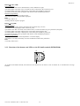
2.3.2 Functions of the buttons and LEDs on the PJ Small terminal (PST00SR300)
6
8
7
As regards the PJ Small terminal, the functions of the buttons are the same as seen for buttons (, ) and *on the PJ Large
terminal.
Carel code +030220221 Rel. 1.1 dated 18/11/04
10
MasterCase
3. Installation
3.1 Electrical connections
For details on the electrical connections to the main board, see the layout shown above.
WARNINGS
Avoid installing the controllers in environments with the following characteristics:
1. Relative humidity greater than 85%, non-condensing
2. Heavy vibration or shocks
3. Exposure to continuous water sprays
4. Exposure to corrosive or pollutant gases (e.g. sulphur or ammonia fumes, saline mist, smoke) so as to avoid corrosion and
oxidisation
5. Strong magnetic and/or radio interference (therefore avoid installing the unit near transmitting antennae)
6. Exposure of the controllers to direct sunlight or the elements in general.
The following warnings must be heeded when making the connections during the pre-installation of the controllers:
1. The incorrect connection of the power supply may seriously damage the system.
2. Separate the probe signal and digital input cables as much as possible from the power and inductive load cables, to avoid
possible electromagnetic disturbance. Never lay the power cables and the probe cables in the same conduits. Avoid installing
the probe cables in the immediate vicinity of power devices (thermal magnetic circuit breakers and the like). Reduce the path of the
probe cables as much as possible, and avoid paths that surround power devices. Only use IP67 sensors for the end defrost probe;
position the probes with the bulb placed vertically to assist the draining of any condensate. Remember that the thermistor
temperature probes (NTC) have no polarity and therefore can be connected in either order.
3. If a connection to the supervisory network is envisaged, connect the shield of the 485 cable to the 485 ground on the
instrument.
4. In the MGE0000020 models, if a series of units are installed in the same electrical panel, do not supply the 24 Vac from a
common transformer, but rather use a different transformer for each MasterCase.
5. The secondary of the transformers must not be earthed.
3.2 Configuration of the controllers
3.2.1 Parameters directly relating to the hardware
When configuring an instrument that has just been installed, there are a number of parameters that are strictly related to the
hardware connections.
These parameters are as follows:
• A1, A2,…, A5: configuration of the digital inputs;
• /A: probes present;
• /4: virtual control probe (determines which probe is used for the control functions)
• /7: presence of the remote display (determines the presence of the device and which probe is displayed on the remote display)
• H5, H6: configuration of the auxiliary outputs (AUX1 and aux2);
• H7: configuration of the control output (compressor output);
• P1(*): type of valve;
• Pi(*): type of pressure sensor;
• PH(*): type of refrigerant used in the system.
(*)
only for models with the electronic valve control, code MGE0000020
For the meaning and configuration of the parameters, see the corresponding section further on in the manual.
Carel code +030220221 Rel. 1.1 dated 18/11/04
11
MasterCase
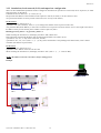
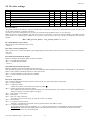
3.2.2 Stand-alone, local network (LAN) and supervisor configuration
There are three fundamental parameters used to configure an instrument for operation in a network (LAN or supervisor) or standalone operation: In, H0 and Sn.
In defines the unit as master (In= 1) or slave (In= 0);
H0 represents the address of the instrument in the supervisor network, if master, or in the LAN for a slave;
Sn represents the number of slaves present in the LAN (to be set only on the master).
for the master:
• the parameter "In" must be set to 1;
• parameter "Sn" (slave number): from 1 to 5, according to the number of slaves present in the LAN;
• the parameter H0 (Serial address), in the event of connection to a supervisor network, must be set to a value equal to the sum of
the address of the previous master plus its number of slaves plus one, that is:
H0= H0_previous_master + Sn_previous_master + 1
When switching the instrument on, the display will show "uM", Master unit.
If the instrument is fitted with the RTC card, the following parameters also need to be set:
• parameters "td", "th", "t": day of the week, hour, minute;
• parameters "dx", "hx", "mx" (with x= 1, 2,..., 8): days, hours and minutes corresponding to the defrost times, with 1 minute
resolution (for defrosts at preset times).
for the slaves:
• the parameter "In" must be set to 0;
• parameter "H0": address of the slave in the LAN.
When switching the instrument on, the display will show "uSx" (with x= 1,…, 5 - value of "H0").
NOTE: The addresses must be consecutive, always starting from 1.
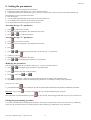
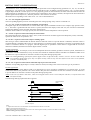
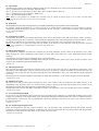
Example:
PlantVisor®
Master
Slave 1
Slave 2
In=1
Sn=2
H0=1
In=0
H0=1
In=0
H0=2
Master
Slave 1
Slave 2
In=1
Sn=2
H0=4
In=0
H0=1
In=0
H0=2
Carel code +030220221 Rel. 1.1 dated 18/11/04
12
MasterCase
3.2.3 Selecting the main operating parameters
Setting the set point
The set point (parameter "St") is the main parameter, as it represents the reference value for the operation of the instrument.
It is simple to access and set, and this is done separately from the other parameters.
The default set point of the instrument is -20ºC.
If this value is not compatible with the application, it can be modified as follows:
button for one second to display the value of the set point.
• press the
The value flashes;
• the value of the set point can be increased or decreased using the
• press
and/or
buttons, until displaying the desired value;
again to confirm the new value.
Parameters relating to the set point
Differential (control hysteresis) – parameter "rd"
The default of this parameter is 2°C.
The value is "RELATIVE", that is, it is related to the set point, being added to this value.
The set point represents the point at which the instrument is switched off, while the activation point (ON) is equal to the
set point (St) + differential (rd):
Temperature alarm thresholds – parameters "AH", "AL" and "Ad"
These parameters are used to set the temperature thresholds above which the alarms are activated (activation of the alarm relays
and the buzzer on the terminal).
For these parameters too the value is "RELATIVE" to the set point.
AH: high temperature alarm;
AL: low temperature alarm;
Ad: delay time from when the threshold is exceeded to the activation of the alarm, in minutes.
The actual temperature thresholds are determined as follows:
high temperature threshold= set point (St) + AH;
low temperature threshold= set point (St) - AL;
The default values of these parameters are AH= 0 and AL= 0 (alarms not enabled) and the delay is Ad= 120 minutes.
Main defrost parameters
If the instrument is used for managing the defrost function, a number of parameters need to be checked when starting the
instrument, in particular:
• dI: interval in hours between defrosts (if set times with the RTC option are not used);
• dP: maximum defrost duration;
• d0: type of defrost;
• dt: end defrost temperature.
3.2.4 Loading the default values of the parameters.
During the installation of the instruments the operating parameters may be set incorrectly.
In other cases, significant electromagnetic disturbance may cause errors on the instrument when saving the data, with the display
of the error "EE" (data saving error).
In these and in other cases it may be useful to reset the instrument by assigning the parameters the default values.
To perform this operation, proceed as follows:
•
disconnect the instrument from the power supply;
•
•
and Down
at the same time and switch the instrument back on while holding the buttons;
press Set
when the display shows the combination of characters "-- 3", release the buttons.
At this point the instrument is automatically rebooted and is ready to operate correctly.
NOTE: If the error "EE" occurs quite frequently, the controller should be checked as the memory may be compromised and the
initial precision not guaranteed.
Carel code +030220221 Rel. 1.1 dated 18/11/04
13
MasterCase
4. LAN functions
The MasterCase instruments can be connected together to create a LAN (Local Area Network), in master-slave configuration.
The main purpose of the LAN is to allow communication between as series of instruments (maximum six: one master and five
slaves) with synchronised operation, for the control of multi-evaporator utilities, such as multiplexed showcases.
Each instrument can be configured as either the master or a slave by simply setting a parameter.
This configuration allows the synchronisation and coordination of defrosts, the propagation of the status of the digital inputs, as
well as display on the master of any alarms active on the slaves.
The particularly reliable structure of the LAN (16-bit CRC error checking) means the values read by the control temperature
and/or pressure probe on the master can be shared across the network, thus allowing a saving in the number of probes required.
Finally, as regards the supervision software, the master acts as the interface for the slaves, as only the master needs to be fitted
with the serial card and connected to the RS485 line to be able to manage all the instruments in the local network.
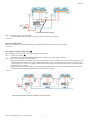
4.1 Network defrost in multiplexed installations
One of the functions that most requires synchronisation is the defrost function. The master controls the defrosts on all of the
slaves connected.
It waits for the defrost to be completed on all of the units before sending the end network defrost signal.
The slaves that have completed the defrost must wait for the end defrost signal from the master before switching to the dripping
phase. Once the end defrost signal is received, the slaves go into dripping mode.
The defrost on each single unit and the network defrost are in any case stopped after the maximum defrost time, set using the
parameter ("dP", default 30 min.).
The network defrost is performed cyclically, at a programmable interval set for the parameter dI. It can also be started:
- manually (pressing
for 5s on the master);
- at set times (if the RTC option is present).
4.2 Remote alarm signals.
The unit configured as the master in a LAN can signal remote alarms present on the slave units, if enabled by setting the
corresponding configuration parameter (parameter Ar = 1). All the masters are enabled for this function as default.
If a terminal or display is not essential for the operation of the unit, and indeed in a LAN the slave can operate perfectly without
such user interface, this function is particularly useful for "centralising" the alarm management functions on the master.
If the master detects an alarm on a slave unit (probe error, high or low temperature error, etc....), the display shows the signal
"nX" (alternating with the display of the temperature) where X = 1, 2, 3, ... 5, the LAN address of the slave in question. When the
event occurs, the alarm relay on the master is activated.
The "nX" signal on the master unit can be inhibited for one minute by pressing
.
4.3 Transmission of control signals and probe readings
The particularly reliable and fast structure of the LAN (16-bit CRC error checking) allows the value read by the control probe
and/or pressure probe to be sent across the network, allowing savings in terms of both materials installed and installation time.
The transmission of the pressure probe signal must be enabled on the master using the parameter "PA", and the slave must be
enabled to receive the signal suing the parameter "Pb".
The control probe temperature sent by the master is set on the slaves by setting parameter "/A"=4.
Carel code +030220221 Rel. 1.1 dated 18/11/04
14
MasterCase
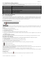
5. Setting the parameters
The parameters have been grouped into two families:
• Frequent parameters (indicated by type F in the parameter tables)
• configuration parameters (indicated by type C), with access protected by a password to prevent unwanted tampering.
The parameters can be programmed as follows:
• from the keypad
• via LAN (download parameters from master to the connected slaves)
• via an RS485 serial connection, if the optional card is fitted.
To set the parameters from the keypad, proceed as follows.
Accessing the type "F" parameters
• press
for more than 5 seconds;
• the display shows the parameter "PP" (Parameter Password);
• press
and
to scroll the parameters.
Accessing the type "C" parameters
• press
for more than 5 seconds;
• the display shows the parameter "PP" (Parameter Password);
• press
;
• press
or
until displaying 22 (password to access the type "C" parameters);
.
• confirm by pressing
• the display shows the parameter "PP" again;
• press
or
until displaying the parameter to be modified.
Modifying the parameters
After having displayed the first parameter, either type C or type F, proceed as follows:
• press
or
• press
to display the value of the parameter;
until displaying the parameter to be programmed;
• modify the value using
and/or
;
• press
to temporarily confirm the values saved and return to the display of the parameter code;
• repeat all the operations in the point "Modifying the parameters" to modify the values of other parameters.
Saving the new values:
• press the SET button
Important: only pressing
for five seconds per save the new value/values entered and exit the parameter modification procedure.
permanently saves the temporary values entered during the operation.
If the instrument is switched off before pressing
for five seconds, all the changes made and temporarily saved will be lost.
Exiting the programming procedure
To exit the procedure without modifying the parameters, do not press any button for at least 30 seconds (exit by TIMEOUT).
In this way, the instrument returns to normal operation without making any modifications to the parameters.
Carel code +030220221 Rel. 1.1 dated 18/11/04
15
MasterCase
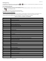
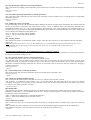
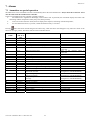
5.1 Classification of the parameters
The parameters, as well as being divided by TYPE, are grouped into logical categories identified by the first letter or symbol. The
following table shows the categories and the corresponding letters/symbols.
Letter/Symbol
/
r
c
d
A
F
H
t
P
Category
temperature probe management parameters
temperature control parameters
safety and control activation time parameters
defrost management parameters
alarm management parameters
evaporator fan management parameters
general configuration parameters (addresses, enabling, etc.)
clock and HACCP parameters
electronic valve management parameters
5.2 "Password" parameters
PP: access level password
The first parameter encountered when entering programming mode is a "password" parameter that allows access to all the
parameters of the instrument; if the password is not entered, only the type "F" parameters can be accessed. This prevents access to
the "C" parameters by unauthorised persons. Once having accessed the configuration parameters, the type "F" parameter can also
be modified. The procedure for accessing and modifying the parameters is described above.
PS: alarm log password
• after having reached the parameter "PS" (Password Log).
• enter 44 as the password for accessing the alarm log
• press
for more than 5 seconds to access the log.
ALARM LOG
All models of the MasterCase series feature an alarm log that saves up to 10 events. The models fitted with RTC also allow "the
age" of each alarm to be saved, that is, the time in hours that has elapsed from when the alarm was recorded to when the log is
accessed.
The following events are saved in the log:
• the high and low temperature alarms ("HI", "LO");
• the control probe error ("rE");
• the end defrost probe error ("E2");
• the defrost by temperature ended by timeout signal, if enabled as an alarm ("Ed");
• the loss of LAN communication by a controller in network, either the master unit or those configured as slaves ("MA" and
"ux, with x= 1…5").
Accessing the display of the log
The alarm log is displayed by entering the value 44 for the password parameter “PS” and confirming by pressing the Set button for 5 seconds.
Description of the alarm log
If the alarm log is empty, the display shows three bars (\\\), otherwise the following information is displayed in sequence:
• the index of the alarm in the log, preceded on the left by a graphic symbol;
• the code of the alarm;
• the time elapsed in hours (only for units fitted with RTC) since the event was saved.
If the RTC is not fitted, the time is replaced by the symbol "_ _ _".
The three displays are shown cyclically in succession. In the log is scrolled by pressing the arrow buttons:
•
to display the older alarms
•
to display the more recent alarms.
The log can save 10 events. The alarms appear in the log according to the order they were saved in.
When a new alarm is saved, the older alarms are moved back a position in the list. If the log is full, the new alarm deletes the
oldest alarm (FIFO logic: First In First Out).
If an alarm has been present in the log for over 199 hours, its age is replaced by the graphic symbol "_ _ _".
NOTE: If the current time value is lost on the instrument, the display shows "tC" and the age of all the alarms saved is replaced
by the graphic symbol "_ _".
Exiting the log
Exit the display of the log by pressing
for one second, or alternatively do not press any button for 30 seconds.
Carel code +030220221 Rel. 1.1 dated 18/11/04
16
MasterCase
Deleting the log
The alarm log can be deleted by pressing and holding
and
the operation the controller will exit the display of the log.
together for 5 seconds when the log is displayed. At the end of
Pd: download password
• after having reached the parameter "Pd" (Download Password).
• enter 66 as the password on a master unit with slaves, to download the parameters from the master to the slaves for the
configuration of a multiplexed island
• press
for more than 5 seconds to perform the download.
When the temperature is displayed again the download is complete.
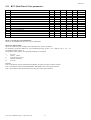
DOWNLOAD PARAMETERS
All the MasterCase series instruments feature the possibility of transferring the values of the parameters from the master to the
slaves via the LAN. This operation saves time when programming instruments in the same LAN with similar settings.
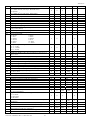
The table below lists the parameters that can be transferred via LAN from the Master to the Slaves.
TABLE OF DOWNLOADABLE PARAMETERS
CODE
DESCRIPTION
/4
/6
/7
/9
/A
/t
A0
A7
Ad
AH
AL
c0
c1
c2
c3
c4
c6
c8
cc
d0
d2
d3
d4
d5
d6
d7
d8
d9
dd
dI
dP
dt
F0
F1
F2
F3
Fd
H1
H3
H4
r1
r2
r3
r4
r5
r6
rd
St
Virtual probe (%)
Enable decimal point to display the temperature
Remote display management
Use third probe as end defrost probe
Presence of probes
User interface management
Fan alarm differential
Digital input reading delay time
Delay in reading high and low temperature alarms
High temperature alarm upper band
Low temperature alarm lower band
Start control delay on power-up
Minimum time between two successive starts
Minimum OFF time
Minimum ON time
Safety control (Duty Cycle Setting function)
Temperature alarm bypass time after continuous cycle
Start control delay from the opening of the valve
Duration of the "continuous cycle"
Type of defrost
Type of control for local network defrost
Compressor operating time with temperature < 1°C before starting a defrost
Defrost when switching the instrument on (YES/NO)
Defrost delay when switching the instrument on
Management of the terminal display and remote display during the defrost
Enable skip defrost
Alarm bypass time after defrost
Defrost priority over compressor safety
Dripping time
Interval between defrosts
Maximum defrost duration
End defrost temperature
Fan management (always on or slave to the fan controller)
Fan set point
Fans off when compressor off
Fans off in defrost
Fans off in post-dripping
Enable/disable remote control
Enable ON/OFF from the keypad
Enable ON/OFF from supervisor
Minimum temperature set point allowed by the user
Maximum temperature setting
Enable defrost ended by timeout signal
Night-time set point variation
Enable maximum and minimum temperature monitoring
Enable night-time control with the third probe
Control differential
Control set point
Carel code +030220221 Rel. 1.1 dated 18/11/04
17
MasterCase
Download failed signals
The master displays the failure of the download to a slave by showing the signal (alternating with the temperature) "dx", where x
= 1, 2, ..., 5, that is, the value of the parameter "H0" corresponding to the slave on which the "data transfer" via LAN operation
failed.
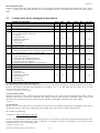
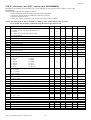
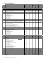
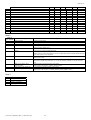
5.3 /= temperature probe management parameters
/
/2
/4
/6
/7
/8
/9
/A
/C
/d
/t
PROBE PARAMETERS
Measurement stability
Virtual probe (between S1 and S3)
(0= probe 1; 100= probe 3)
Enable decimal point (0= No, 1= Yes)
Remote display management
only if a user terminal is connected
0= not present
1= room probe (S1)
2= end defrost probe (S2)
3= third probe (S3)
4= virtual probe
5= terminal probe
Third probe calibration (S3)
Defrost also with third probe (S3)
1= the defrost finishes when the temperature of probes S2 and
S3 are greater than "dt" (see also parameter "H5")
Probes present
0= room probe only (S1)
1= room probe (S1) and third probe (S3)
2= room probe (S1) and defrost probe (S2)
3= all present (S1), (S2) and (S3)
4= control probe sent by master (only on the slaves)
Room probe calibration (S1)
End defrost probe calibration (S2)
User terminal display management
0= not present
1= room probe (S1)
2= end defrost probe (S2)
3= third probe (S3)
4= virtual probe
5= terminal probe
Type
C
Min.
1
Max.
15
UOM
-
Def.
1
Via LAN
C
0
100
-
0
•
C
0
1
flag
1
•
C
0
5
-
0
•
C
-20.0
20.0
°C
0.0
C
0
1
flag
0
•
C
0
4
-
0
•
F
C
-20.0
-20.0
20.0
20.0
°C
°C
0.0
0.0
C
0
5
-
4
•
/C: calibration or offset of the room probe (S1)
The value assigned to this parameter is added to (positive value) or subtracted from (negative value) the temperature measured by
probe S1. For example, to decrease the temperature by 2.3 degrees, set /C = -2.3. The offset may be set from -20 to +20 with
precision to the tenth of a degree
- Default: 0.0 (no offset to probe reading).
/2: measurement stability
Defines the coefficient used to stabilise the temperature measurement. Low values assigned to this parameter offer a prompt
response of the sensor to variations in temperature; the reading is however more sensitive to disturbance. High values, on the
other hand, slow down the response but guarantee greater immunity to disturbance, meaning a more stable reading.
- Default: 1.
/4: virtual probe:
Defines a non-existent probe used for the normal control functions This parameter determines the weighted average used to
calculate the reference control probe value based on the reading of the room probe (S1) and the third probe (S3).
The formula is the following:
virtual probe=
(100 − ("/4" )) xS1 + ("/4" ) xS 3
;
100
If set to 0, the virtual probe coincides with the room probe (S1); if set to 100, the virtual probe coincides with the third probe (S3).
If control is based on the virtual probe (value of parameter "/4" between 0 and 100), the breakage of one of the two probes
automatically moves control to the other probe.
- Default: 0, room probe (S1).
Carel code +030220221 Rel. 1.1 dated 18/11/04
18
MasterCase
/6: decimal point
Enables or disables the display of the temperature with resolution to the tenth of a degree, in the range between -9.9 and 99.9 for
the version with Small display, and between -99.9 and 999.9 for version with Large display.
0= display without decimal point;
1= display with decimal point.
- Default: 1, decimal point used.
/t: display on user interface
Selects the probe reading displayed on the interface terminal
0= Not present
1= Room probe (S1)
2= End defrost probe (S2)
3= Third probe 3 (S3)
4= Virtual control probe (depending on parameter /4)
5= Terminal probe (if present)
- Default: 4, display virtual probe.
/7: display on remote display
Selects the probe reading displayed on the remote display:
0= Not present
1= Room probe (S1)
2= End defrost probe (S2)
3= Third probe (S3)
4= Virtual control probe (depending on parameter /4)
5= Terminal probe (if present)
Warning: The remote display (code PST00VR100) only works if a terminal is also connected (code PST00SR300 or
PST00LR200).
- Default: 0, display not present.
/8: third probe calibration
The value assigned to this parameter is added to (positive value) or subtracted from (negative value) the temperature measured by
probe S3. For example, to decrease the temperature by 2.3 degrees, set /8 = -2.The offset may be set from -20 to +20 with
precision to the tenth of a degree.
- Default: 0.0 (no offset to probe reading).
/9: defrost with probe 3
This parameter allows the third probe S3 to be used as the end defrost probe together with probe S2. In this case, the defrost by
temperature ends when the temperature measured by both the probes is greater than or equal to the end defrost temperature (see
parameter "dt"). Consequently, probe 3 can be used as a defrost probe on a second evaporator. When programming an auxiliary
output as a defrost output, separate and independent management of the defrost on the second evaporator can be enabled by using
probe S3 to manage the end defrost temperature (see parameters "H5" and "H6").
- Default: 0.
/d: end defrost probe calibration (S2)
The value assigned to this parameter is added to (positive value) or subtracted from (negative value) the temperature measured by
probe S2. For example, to decrease the temperature by 2.3 degrees, set /C = -2.The offset may be set from -20 to +20 with
precision to the tenth of a degree
- Default: 0.0.
/A: probes present
The value of this parameter tells the instrument whether the probes S2 and/or S3 are connected. The value of 4 only makes sense
on controllers configured as slaves as, with this setting, the slaves no longer uses their own probes for the control functions, but
rather use the probe reading sent by the master.
Do not set the value 4 on a controller configured as master
The possible values of this parameter are as follows:
0= defrost probe and third probe absent
1= defrost probe absent and probe 3 present
2= defrost probe present and probe 3 absent
3= defrost probe and probe 3 both present
4= control probe sent by the master (only for the slaves).
The room probe (S1) is always considered as being present.
- Default:0.
Carel code +030220221 Rel. 1.1 dated 18/11/04
19
MasterCase
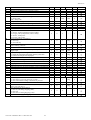
5.4 r= temperature control parameters
r
r1
r2
r3
r4
r5
r6
rd
rH
rL
rt
CONTROL PARAMETERS
Minimum set point value allowed by the user
Maximum set point value allowed by the user
Enable alarm "Ed" (defrost ended by timeout)
0= No, 1= Yes
Night-time set point (deviation from set point)
Enable maximum and minimum temperature recording
0= No; 1= Yes
Night-time control with third probe S3
1= night-time control on third probe S3
0= night-time control on virtual probe
Differential (hysteresis)
Maximum temperature recorded in the interval "rt" (read-only
parameter)
Minimum temperature recorded in the interval "rt" (read-only
parameter)
Time elapsed since the start of the maximum and minimum
temperature recording interval (read-only parameter)
Type
C
C
Min.
-50.0
r1
Max.
r2
90.0
UOM
°C
°C
Def.
-50.0
90.0
Via LAN
•
•
C
0
1
flag
0
•
C
-20.0
20.0
°C
3.0
•
C
0
1
flag
0
•
C
0
1
flag
0
•
F
0.1
20.0
°C
2.0
•
C
-
-
°C
-50.0
C
-
-
°C
90.0
C
0
999
hours
0
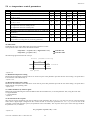
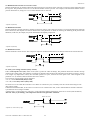
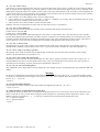
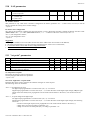
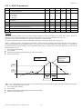
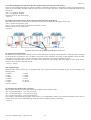
rd: differential
Establishes the value of the differential used in the temperature control.
The operation of this value can be described as follows:
temperature > set point ("St") + differential. ("rd")
temperature ≤ set point ("St")
! controller ON
! controller OFF
The following figure illustrates the concept:
Direct (freddo/cooling)
rd
on
actuator
attuatore
off
Set point
- Default: 2.0.
r1: Minimum temperature setting
Determines the minimum value that can be set for the set point. This parameter prevents the user from setting a set point that is
lower than the value indicated by r1.
- Default: -50.0.
r2: Maximum temperature setting
Determines the maximum value that can be set for the set point. This parameter prevents the user from setting a set point that is
higher than the corresponding value.
- Default: 90.0.
r3: enable end defrost by timeout signal
Enables the signal indicating the end of the defrost after the maximum time, set for the parameter "dP", using the code "Ed".
0= Signal disabled
1= Signal enabled
- Default: 0.
r4: deviation from the set point
The value set for this parameter will only be effective if the parameter "Stn" is set to 1 or In this case, the set point will change
either when a digital input configured as the "curtain switch" is closed (see parameters A1...A5 = 7), or at a set time if the
controller is fitted with the RTC option (see parameters "hSn" and "hSd"). The set point varies by the value with sign saved for
the parameter "r4", as follows:
new_set point= set point ("St") + "r4"
- Default: 3.0.
Carel code +030220221 Rel. 1.1 dated 18/11/04
20
MasterCase
r5: enable temperature monitoring
Enables temperature monitoring, recording the maximum ("rH") and minimum ("rL") temperatures reached in the interval "rt"
(max 999h).
r5= 0: temperature monitoring disabled
r5= 1: temperature monitoring enabled on probe S1
The monitoring starts from when "r5" is assigned the value 1.
To disable temperature monitoring, set "r5" to 0. After 199 hours, the maximum monitoring time allowed by the instrument, the
max. and min. temperatures are no longer recorded. Set "r5" again to start a new monitoring cycle.
- Default: 0.
r6: control with the third probe from digital input
This is used to move the temperature control to the third probe (S3) when a digital input configured as the "curtain switch" is
closed (see parameters A1...A5 = 7).
r6= 0: no movement, control with virtual probe
r6= 1: when the digital input closes control is performed on probe S3
- Default: 0.
rt: temperature monitoring time
Once the temperature monitoring function (parameter "r5") has been enabled, this parameter records the time in hours from the
start of the monitoring cycle.
Read-only parameter
- Default: 0.
rH: maximum temperature measured in the time "rt"
Once the temperature monitoring function (parameter "r5") has been enabled, this parameter records the maximum temperature
reached since the start of the monitoring cycle.
Read-only parameter
- Default:, -50.0.
rL: minimum temperature measured in the time "rt"
Once the temperature monitoring function (parameter "r5") has been enabled, this parameter records the minimum temperature
reached since the start of the monitoring cycle.
Read-only parameter
- Default: 90.0
5.5 c= times and safety parameters
c
c0
c1
c2
c3
c4
c6
c8
cc
SAFETY TIME PARAMETERS
Start control delay from power up
Minimum time between two successive starts
Minimum OFF time
Minimum ON time
Safety control ("Duty cycle setting" function)
0= always OFF
100= always ON
Temperature alarm bypass time after continuous cycle
Start control delay from the opening of the valve
Continuous cycle duration
Type
C
C
C
C
Min.
0
0
0
0
Max.
15
15
15
15
UOM
min
min
min
min
Def.
0
0
0
0
Via LAN
•
•
•
•
C
0
100
min
0
•
C
C
C
0
0
0
15
120
15
hours
s
hours
2
5
4
•
•
•
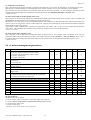
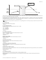
c0: Control start delay when switching the instrument on
This parameter is used to delay, by a set time in minutes, the activation of the control functions from when the instrument is
switched on. In multi-utility installations, the parameter "c0" can be used to avoid simultaneous starts of the various units, thus
preventing the overloading of the refrigeration system when starting.
ON
Accensione strumento
Power ON
OFF
ON
Richiesta intervento
Insertion request
OFF
ON
Compressore
Compressor
OFF
- Default: 0 (minutes).
Carel code +030220221 Rel. 1.1 dated 18/11/04
21
MasterCase
c1: Minimum time between two successive starts
Sets the minimum time (in minutes) that must elapse between two activations of the controller, irrespective of the temperature and
the set point. This parameter can be set so as to limit the number of starts per hour. For example, if the maximum number of starts
per hour allowed is 10, simply set c1=6 to ensure that this limit is observed.
- Default: 0 (minutes).
c2: Minimum OFF time
Sets the minimum controller off time in minutes (compressor output). The compressor output is not reactivated until the minimum
time selected (c2) has elapsed since the last deactivation. This parameter is useful for ensuring the balancing of the pressure after
shut-down, in the case, for example, of systems with hermetic and capillary compressors.
- Default: 0 (minutes).
c3: Minimum ON time
Sets the minimum control on time. The compressor output is not deactivated unless it has been activated for at least the time set.
- Default: 0 (minutes).
c4: "Duty cycle setting" function (safety control)
If the "control probe error (rE)" alarm occurs (that is, probes S1 and/or S3 faulty), this parameter allows the controller to keep
operating the cooling utility, thus reducing or limiting any damage while awaiting the elimination of the fault. In practice, as there
is no longer any temperature control, the controller operates in cycles, with an ON time equal to the value assigned to the
parameter "c4" (in minutes) and a fixed OFF time of 15 minutes.
Two values of c4 bring about specific situations:
"c4"= 0, control deactivated (always OFF);
"c4"= 100, control always active (always ON).
If control error occurs while the controller is in a defrost or continuous cycle, it instantly exits the current status and goes into
"duty setting" mode.
It should be remembered that, in the event of a control error on a master/slave unit, local or manual defrosts and the continuous
cycle functions are no longer available.
A master with a "control probe error (rE)" may, on the other hand, manage the defrosts on the slaves served (network defrost).
After the "Duty Cycle Setting", the temperature alarms are bypassed for 5 minutes.
OFF=15 min.
c4
- Default: 0, control always off.
Carel code +030220221 Rel. 1.1 dated 18/11/04
22
MasterCase
cc: continuous cycle duration
This is the time in hours that the controller is operated continuously for so as to lower the temperature, even below the set point.
This function is started manually by pressing the buttons on the user interface. If cc=0, the continuous cycle is disabled.
The controller exits the continuous cycle procedure when the time set for the parameter "cc" has elapsed, or alternatively when
reaching the minimum temperature threshold set using the parameter "AL minimum_threshold = set point - AL).
- Default: 4 (hours).
c8: Start control delay from the opening of the valve
This parameter is used to set the number of seconds that must elapse between the opening of the electronic valve (in models code
MGE0000020) and the activation of the compressor output (start control).
The purpose is to avoid, above all in non-centralised systems with compressor on board, that the time required for the electronic
valve to open is too long for the capacity of the compressor, implying the rapid emptying of the suction line and the consequent
safety shutdown due to low pressure.
Any auxiliary output configured as a solenoid valve (parameters "H5" and/or "H6"= 9) will work in parallel with the electronic
valve, that is, will open before the activation of the compressor output by the set time for this parameter.
- Default: 5 (seconds).
c6: alarm bypass after continuous cycle
This is the time in hours that the low temperature alarm is ignored, that is, not activated, after a continuous cycle. The low
temperature alarm will be generated only if, after a time equal to the sum of "c6" (in hours) + "Ad" (in minutes), where "Ad" is
the general delay for the temperature alarm, the temperature is still below the low temperature threshold (set point - "AL").
- Default: 2 (hours).
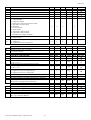
5.6 d= defrost management parameters
d
d0
d2
d3
d4
d5
d6
d7
d8
d9
dd
dI
dM
dPM
dP
dt
DEFROST PARAMETERS
Type
Type of defrost
0= electric, end by temperature, time as safety
C
1= hot gas, end by temperature, time as safety
2= electric, end by time
3= hot gas, end by time
Type of control for LAN defrost
C
0= start only
1= start and stop
Operating time with temperature of S2 lesser than 1°C before
C
starting a defrost
Defrost when switching controller on (Yes, No)
C
Defrost start delay from controller power-up or on from
C
digital input
Display management during defrost
C
0= display the temperature alternating with the symbol "dF"
1= hold on last temperature displayed
Enable skip defrost function
C
Temperature alarm bypass time after defrost and/or open door
F
Priority of defrost over protection times (par. "c")
C
Dripping time
F
Interval between two successive defrosts
F
Time between two successive cleaning cycles (CCM function)
C
Cleaning cycle duration (CCM function)
C
Maximum defrost time
F
End defrost temperature
F
d0: type of defrost
Establishes the type of defrost:
0= electric heater, end by temperature or maximum safety time (timeout)
1= hot gas, end by temperature or maximum safety time (timeout)
2= electric heater, end by time
3= hot gas, end by time
- Default: 0, electric heater defrost, end by temperature.
Carel code +030220221 Rel. 1.1 dated 18/11/04
23
Min.
Max.
UOM
Def.
Via LAN
0
3
-
0
•
0
1
flag
1
•
0
192
hours
0
•
0
1
flag
0
•
0
180
min
0
•
0
1
flag
0
•
0
0
0
0
0
1
0
1
-50.0
1
15
1
15
192
999
60
180
30.0
flag
hours
flag
min
hours
hours
min
min
°C
0
1
0
2
8
1
0
30
4.0
•
•
•
•
•
•
•
MasterCase
d2: type of defrost control
Determines whether the instrument, in a LAN, at the end of the defrost waits for an end defrost signal or not.
"d2"= 0, the instrument completes the defrost without waiting for the stop signal (stand-alone instrument);
"d2"= 1, the instrument waits, at the end of the defrost, for the stop signal, which is usually sent by the master in a LAN of
multiplexed cabinets.
Default: 1.
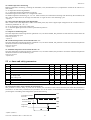
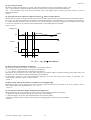
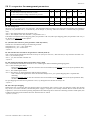
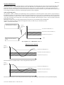
d3: operating time with evaporator temperature below 1°C before starting a defrost.
Determines how long the controller operates (solenoid valve output/compressor active) when the temperature measured by probe
S2 is below 1(C, after which a defrost is performed. To disable this function set the parameter to 0. For temperature values above
1°C and/or when the controller is inactive, the time is not counted. Obviously, the time is managed by an incremental counter that
is set to zero only after the set value has been reached and the corresponding defrost performed.
Default: 5 (hours).
Temp. S2 °C
1°C
time
Control
ON
OFF
t1
time
t2
t1 + t2 +… tn ≥ d3 ! Start defrost
d4: defrost when the instrument is switched on
Starts a defrost when the instrument is switched on. The possible values are:
0 = no, no defrost is performed when switching the instrument on;
1 = yes, a defrost is performed when switching the instrument on.
This function may be useful in cases where, due to frequent power failures and the consequent resetting of the defrost timer (see
parameter "dI"), the number of defrosts performed may be insufficient.
In multi-utility systems, to avoid the simultaneous defrosting of all the units when power returns, set parameter "d5",
corresponding to the defrost delay, to different values.
- Default: 0.
d5: defrost delay when the instrument is switched on or from digital input
Represents the delay time in minutes before starting a defrost when the instrument is switched on (as set by parameter "d4") or
from a digital input (set with parameters A1...A5 = 3 or 4).
- Default: 0.
d6: user interface and remote display management during defrosts
During the defrosts, two types of behaviour can be set for the user interface and the remote display:
0= display the temperature alternating with the symbol "dF" on both displays;
1= hold both displays on the last value displayed before the start of the defrost.
The display normally returns on both devices after the post-dripping phase (with normal control enabled).
- Default: 0.
Carel code +030220221 Rel. 1.1 dated 18/11/04
24
MasterCase
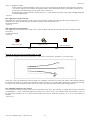
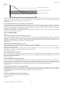
SKIP DEFROST
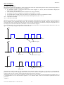
d7: enable "skip defrosts"
This parameter enables the algorithm by which, based on the actual time elapsed during the last defrost, the following defrost is
performed or skipped. The following rules are considered:
• the maximum number of consecutive defrosts that can be skipped is 3, that is, after the third defrost skipped, the
following one is always performed;
• after switching the instrument on, the first 8 defrosts are always performed;
• the number of events to be skipped is increased by a maximum of 1 at a time;
• the manual defrosts (started on the user interface) or by digital input are always performed and counted;
• the function can only be used with the defrosts that end at temperature ("d0" = 0 or 1).
"d7" = 1 skip defrosts enabled;
"d7" = 0 skip defrosts disabled.
This function is based on a very simple but very effective principle. If the defrost lasts less than or equal to 65% of the time set
for the parameter "dP" (maximum defrost time), the next defrost envisaged will be skipped. When the following defrost is
performed, the check is repeated, and if the outcome is the same then the following two defrosts envisaged are skipped, and so on
according to the criteria described above (maximum 3 successive defrosts skipped).
As soon as the defrost time exceeds 65% of the time "dP", the following defrost will be performed and the function will start
again. The following is a graphic representation of the function.
Def
time
< 65%
Def
Defrosts to be skipped
time
< 65%
Manual < 65%
Expected defrosts skipped
Def
time
< 65%
< 65%
Evaluation recommences
Manual > 65%
This function should be used with the programming of the defrosts equally distributed over the day (e.g. cyclical defrosts,
parameter "dI"). This prevents skipping defrosts that would be the last before a long period programmed without defrosts (for
example, when the clock is used to program the defrosting of the utility at night only).
Although this function can be used in combination with the other cases (for example, the function defined by parameter "d3"), it
is recommended not to use these functions together so as to maintain better control over the defrosts performed and to be
performed.
- Default: 0.
Carel code +030220221 Rel. 1.1 dated 18/11/04
25
MasterCase
d8: alarm bypass time after defrost and/or door open
Indicates the time the temperature alarm signal is ignored from the end of a defrost and/or after the switching of a digital input
configured as the "door switch" (see parameters A1...A5). In the latter case, it also indicates the maximum opening time for the
door, in other words, after the set time, if the digital input (door) is still open, the instrument will start the control functions again,
with an alarm signal on the display.
- Default:1 (hours).
d9: priority of the defrost over the safety times and the activation of the control
Cancels the safety times set using the parameters in family "c" when starting the defrost.
0= the protection times are observed;
1= the defrost has higher priority and the times set with the "c" parameters are ignored.
- Default: 0.
dd: dripping time
This parameter is used to set the time in minutes following a defrost in which the controller and the evaporator fans (see
parameter "F3") are stopped, so as to allow the evaporator to drip.
- Default: 2 (minutes).
dI: interval between "cyclical" defrosts
The parameter "dI" manages the so-called "cyclical" defrosts, in that they are repeated after the number of hours set for the
parameter. The time is reset every time a defrost is performed (including non-cyclical defrosts). If the time "dI" is equal to 0 (dI=
0), the cyclical defrosts are disabled. In a LAN, a cyclical defrost on the master also starts a defrost on the slaves connected
(network defrost).
- Default: 8 (hours).
CASE CLEAN MANAGEMENT
This function is used to manage the periodical cleaning of the showcase. By setting two specific parameters ("dM" and "dPM")
and selecting a digital input (see parameters "A1"..."A5"), the instrument can be programmed to "signal" the need for cleaning
and "oblige" the user to intervene.
The instrument enters "standby" status (only after the opening of the digital input), in which the control functions are stopped and
the inputs and outputs deactivated.
The function is active only if one of the digital inputs is set as a "case cleaning input" ("Ax"=10).
dM: time between two successive cleaning signals
This parameter is used to set the time in hours (range 1 1000) between one cleaning signal and the next. The time is counted
starting from when a digital input is set ("Ax" to 10) or when the instrument is switched on and one of the inputs has already been
set to that value. When the time has elapsed, the instrument displays the message "CCM" and the buzzer sounds. The buzzer can
be muted in the normal way or by opening the corresponding digital input.
- Default: 1 (hours).
dPM: cleaning signal duration
This parameter is used to set the time in minutes (range 0 60) for the duration of the cleaning signal. When the time "dM" has
elapsed, the controller awaits the opening of the digital input associated with this function, and only if the input remains open for
a time at least equal to "dPM" will the signal on the display ("CCM") be cancelled and, unless already deactivated manually, the
buzzer muted.. At this point, the counter "dM" will start again for the following signal. Otherwise the buzzer will sound again and
the signal will remain on the display.
- Default: 0 (minutes).
dP: maximum defrost duration
Determines the duration of the defrost in minutes for defrosts by time ("d0" = 0 or 1). For defrosts by temperature ("d0" = 2 or 3),
"dP" represents the maximum safety duration of the defrost, that is, the defrost will in any case stop after the time "dP", even if
the end defrost temperature has not been reached.
- Default: 30 (minutes).
dt: end defrost temperature
This parameter is used to set the evaporator temperature measured by probe S2 at which the defrost is stopped. If when a defrost
is started ("d0" = 0 or 1) the temperature ready by S2 is greater than the value of "dt", the unit goes directly into the dripping
phase. If probe S2 is faulty, the defrost in any case ends after a maximum time (parameter "dP").
- Default: 4.
Carel code +030220221 Rel. 1.1 dated 18/11/04
26
MasterCase
5.7 A= alarm management parameters
A
A0
A1...5
A7
A8
Ad
AH
AL
Ar
ALARM PARAMETERS
Temperature alarm return and fan activation differential (see
parameter F1)
Digital input configuration
Alarm delay from digital input (Ax= 2)
Virtual digital input configuration
Temperature alarm delay
High temperature alarm (deviation from the set point)
Low temperature alarm (deviation from the set point)
Enable the master to signal the alarms on the slaves
(only on the master)
Type
Min.
Max. UOM Def. Via LAN
C
0.1
20.0
°C
2.0
C
C
C
C
F
F
0
0
0
0
0
0
10
180
10
180
20.0
20.0
min
min
°C
°C
0
0
0
120
0.0
0.0
C
0
1
flag
1
•
•
•
•
•
A0: Fan and alarm differential
Represents the differential used to establish the temperature threshold for the deactivation of a high or low temperature alarm
("AL" and "AH") (see the figure below) and for the management of the fans (see parameter "F1").
Allarme bassa temperatura
Low temperatura alarm
Allarme alta temperatura
High temperatura alarm
A0
A0
AL
AH
Set point
- Default: 2.0.
AH: High temperature alarm
This value is related to the set point. It indicates the maximum deviation allowed from the set point above which a high
temperature alarm is activated, indicated by the code "HI" on the display and signalled audibly by the buzzer. In numerical terms:
Control temperature > set point ("St") + "AH" " HIGH TEMPERATURE ALARM ("HI")
Changing the set point therefore automatically changes the alarm threshold.
The point at which the alarm is deactivated is as follows:
Control temperature ≤ set point ("St") + "AH" - "A0"
When the alarm condition is no longer present the corresponding audible signal and message the display are automatically
cancelled.
- Default: 0.0.
AL: Low temperature alarm
the maximum deviation allowed from the set point set point below which a low temperature alarm is activated, indicated by the
code "LO" on the display and signalled audibly by the buzzer. In numerical terms::
Control temperature < set point ("St") - "AL" " LOW TEMPERATURE ALARM ("LO")
Changing the set point therefore automatically changes the alarm threshold.
The point at which the alarm is deactivated is as follows:
Control temperature ≥ set point ("St") - "AL" + "A0"
When the alarm condition is no longer present the corresponding audible signal and message the display are automatically
cancelled.
It should be remembered that the low temperature alarm threshold is also used in the continuous cycle (see parameter "cc") as the
minimum value for stopping the function.
- Default: 0.0.
NOTE: the temperature alarms are not generated in the following cases:
- during a defrost;
- during the continuous cycle.
Ad: temperature alarm delay
Indicates after how many minutes the temperature alarm is signalled from when the corresponding alarm threshold has been
exceeded. If the alarm condition is longer present before the time "Ad" has elapsed, no alarm signal is generated. The temperature
alarm delay has no effect on two special functions: the defrost and the continuous cycle. To delay a temperature alarm after these
functions, use the parameters "d8" for the defrost and "c6" for the continuous cycle.
- Default: 120 (minutes).
Carel code +030220221 Rel. 1.1 dated 18/11/04
27
MasterCase
DIGITAL INPUT CONFIGURATIONS
The MasterCase series instruments feature five digital inputs that can be configured using parameters A1, A2, A3, A4 and A5
(following A1...A5) respectively, associated with the inputs DI1 to D15. In addition, a further parameter, "A8", is used to manage
a digital input called the "virtual" input, as it is not physically present on the instrument, but rather associated with the status of
digital input DI1 on the Master in a LAN (master-slave configuration). On a master controller, the input will be associated with a
specific signal from the Supervisor, otherwise parameter "A8" will have no function.
The functions corresponding to each value of A4...A5 / A8 are described below:
A1…A5 / A8= 0: digital input disabled
The corresponding digital input is not used and ignores the closing/opening of any contacts connected to it.
A1…A5 / A8= 1: input associated with an immediate external alarm
The digital input can be connected to an external alarm that requires immediate activation (for example, high pressure alarm,
etc...). The alarm is generated when the contact is opened, and causes the display of the code "IA", the activation of the buzzer
and the total shutdown of the controller and all the related outputs.
When the alarm condition is no longer present, the unit returns to normal temperature control operation.
A1…A5/A8= 2: input associated with a delayed external alarm
The operating mode is the same as for value 1 above, in this case however the alarm signal can be delayed by a time, in minutes,
equal to the value set for the parameter "A7".
A1...A5/A8= 3: input associated with a defrost enabling signal
This setting is used to enable/disable the defrost function. When the contact is open the defrost is inhibited, when the contact is
closed the defrost is enabled. If the contact is closed, but there is no defrost request, the defrost is obviously not performed. If the
contact is closed and a defrost is in progress, when the digital input is opened the current defrost is stopped and the successive
defrosts are inhibited, until the next time the digital contact is closed.
Possible applications
This function is useful, for example, in the case of multiplexed showcases with hot gas defrost. In these systems, the defrosts are
performed in "islands" and therefore, at any one time, some islands are enabled to defrost, and others are disabled. Another use of
the function is to prevent defrosts on the units accessible to the public during opening times.
NOTE: the enabling/disabling of the defrost from a digital contact is effected locally. A master, with A1...A5/A8=3 and with the
corresponding digital input open, may not defrost locally, while it may start the defrost on the units served (manual,
cyclical or set time defrost).
A1...A5 /A8= 4: input associated with an immediate defrost from external contact
When the corresponding digital input is closed, a defrost is started, according to the criteria set for the type "d" parameters.
Possible applications
This function is useful when defrosts need to be performed on a series of utilities coordinated by an external timer. To avoid
simultaneous defrosts, the parameter "d5" can be used to delay the start of the defrost on each unit. Another use of the function is
to prevent defrosts on the units accessible to the public during opening times.
NOTE: in the case of a master with slaves, when its own digital contact closes a network defrost will start, even if the master will
not defrost locally.
The following drawing explains the above function:
t
tem porizzatore
timer
sbrinam ento / defrost
dP
d5
unità 1
unit 1
sbrinam ento / defrost
dP
d5
unità 2
unit 2
sbrinam ento / defrost
dP
unità 3
unit 3
Richiesta sbrinam ento
Defrost request
KEY:
t= impulse from the timer to start the defrost: the minimum duration must be 0.5 seconds
dP(1)= maximum defrost duration unit 1
d5(2)= defrost delay from external contact for unit 2. This must be greater than dP(1) otherwise the defrosts will overlap
Similar meanings for d5(3) and dP(3)
Carel code +030220221 Rel. 1.1 dated 18/11/04
28
MasterCase
A1…A5 / A8= 5: door switch
This function is used to manage the door switch on a cold room. When the contact (door) is opened, the control functions and the
fans are stopped and the light output is activated. When the contact closes the unit starts again in the previous operating mode,
delaying any temperature alarms for a number of hours equal to the value of the parameter "d8". If the door, and consequently the
contact, remain open for a time greater than "d8", the display shows the alarm code "dr" and the controller returns to the operating
mode it was in prior to the opening of the door. Specifically:
• if the controller was in Duty Setting mode, it returns to Duty Setting;
• if the controller was in continuous cycle mode, it returns to continuous cycle mode, and the maximum duration of the
continuous cycle is extended by the time the door was open;
• if the controller was in defrost mode, it remains in defrost mode;
When the controller is restarted, the set safety times are observed (see type "c" parameters).
A1…A5 / A8= 6: remote ON/OFF
By setting the input for this function the controller can be switched on/off using an external contact.
Contact closed= controller ON;
Contact open= controller OFF.
Switching off is not equivalent to disconnecting power, but rather is a "logical Off", that is, the controller goes into "standby",
ignoring all the digital inputs and outputs, the defrost requests, continuous cycle and Duty Setting. The controller however still
continues to display the temperature, alternating with the message "Off". If the instrument that is Off is a master connected to a
series of slaves, it is in any case able to manage the network defrost and signal the alarms on the remote units.
A1…A5 / A8= 7: curtain switch
The digital input set to this value is used to activate/deactivate the "light" relay output when the corresponding contact is
opened/closed. In addition, if the parameter "Stn" is set to 1, the set point will be varied by the value of the parameter "r4".
A1...A5 / A8= 8: "duty cycle setting" operation
The opening of the contact associated with the digital input set with this value will switch the controller to "duty setting"
operation, as described earlier (see parameter "c4").
A1...A5 / A8= 9: door switch with controller ON
The behaviour of the controller when the digital input set to this value is opened is the same as for the "door switch" (An = 5)
with the difference that in this case the outputs remain active (ON). This configuration can be used in cases where the door is
opened and closed frequently, for short periods (frozen food display cabinets, etc...).
A1...A5 / A8= 10: Case Clean Management
This configuration of the digital input is used to manage the "case cleaning" function, as described earlier (see parameters "dM" and
"dPM").
Warning
For the correct management of the functions associated with the digital inputs, the values of A1...A5, A8 must be different from
one another, or alternatively must be equal to zero. That is, if A1...A5, A8 are assigned values other than zero, the following must
be true: A1 ≠ … ≠ A5 ≠ A8.
- Default: 0.
A7: external alarm detection delay
Sets the delay (in minutes) relating to the external alarm from digital input when A1...A5 / A8= 2.
- Default: 0 (minutes).
Ar: enable the master to signal the alarms on the slaves
This parameter allows the master unit to be enabled to display the presence in its LAN of one or more slaves with alarms. If an
alarm is activated on a slave, on the master the display shows the signal "nx" alternating with the temperature, where x is the
address of the slave in question (x = 1, ..., 5). This type of alarm also activates the buzzer and the alarm relay.
"Ar"= 0, function disabled;
"Ar"= 1, function enabled.
- Default: 1.
Carel code +030220221 Rel. 1.1 dated 18/11/04
29
MasterCase
5.8 F= evaporator fan management parameters
F
F0
F1
F2
F3
Fd
FAN PARAMETERS
Fan management
0= fans always on (except cases F2, F3, Fd)
1= fans controlled according to absolute set point F1
Fan off time
Fans off when control inactive (0= No, 1= Yes)
active only with F0= 0
Fan management during defrost
Fan off time during post-dripping
Type
Min.
Max.
UOM
Def.
Via LAN
C
0
1
flag
0
•
F
-40.0
50.0
°C
5.0
•
C
0
1
flag
1
•
C
F
0
0
2
15
min
1
1
•
•
F0: fan management
The fans can be managed by the "fan controller", which manages them according to the temperature measured by the end defrost
probe S2 (see parameter "F1"), or alternatively can be always on, and stop when the controller is switched off (see parameter
"F2").
"F0"= 0, fans managed based on the parameter "F2";
"F0"= 1, fans subject to the "fan controller " (see parameter "F1").
It should be remembered that if a dripping phase (see parameter "dd" ≠ 0) and/or post-dripping phase (see parameter "Fd" ≠ 0), is
set, the fans are always off in these phases.
- Default: F0=0.
F1: (absolute) fan control set point (parameter valid only if F0=1)
The fans are controlled according to the following formula:
Temperature S2 < "F1" - "A0" ! fans ON;
Temperature S2 ≥ "F1" ! fans OFF.
- Default: 5.
F2: fans off when the controller is off (parameter valid only if F0=0)
This is used to decide whether the fans must be always on (except in cases "F3", "dd" and "Fd") or only when the controller is on.
"F2"= 0, no, fans always ON;
"F2"= 1, yes, fans off when controller off.
- Default: 0.
F3: fan management during defrost (parameter always valid)
This is used to decide whether the fans must be on or off during the defrost and during the dripping phase.
"F3"= 0, fans on during the defrost.
During the dripping wait (in the case of master-slave network defrost) and dripping times (if set by the parameter "dd")
the fans are always off.
"F3"= 1, fans off during the defrost.
"F3"= 2, fans always on, during the defrost and also during dripping.
This is useful in the applications where the fans must always be on, yet a "pause"/dripping time is required after
defrosting.
During the dripping wait (in the case of master-slave network defrost) and dripping times (if set by the parameter "dd")
the fans are always on.
If a post-dripping time has been set (parameter "Fd" ≠ 0), during this time the fans are always off.
- Default: 1.
Fd: fans off in post-dripping
Indicates the time (in minutes) after the dripping phase (see parameter "dd"), known as the "post-dripping" phase, that the fans
stay off for, even if the controller, and thus the power supply to evaporator, have already restarted. This is useful to allow the
evaporator to return to the normal operating temperature after defrosting and to freeze the remaining moisture and droplets, thus
avoiding wetting the goods inside the showcase when the fans are started.
- Default: 1 (minutes).
Carel code +030220221 Rel. 1.1 dated 18/11/04
30
MasterCase
5.9 H= other settings
H
H0
H1
H2
H3
H4
H5
H6
H7
CONFIGURATION PARAMETERS
Serial address
Enable use of the remote control (Infrared)
ID code for using the remote control
Enable ON/OFF button on terminal
Enable ON/OFF from supervisor
Configuration of AUX1 output
Configuration of AUX2 output
Configuration of compressor output (only on the master)
Type
C
C
C
C
C
C
C
C
Min.
0
0
0
0
0
0
0
1
Max.
199
1
99
1
1
9
9
2
UOM
flag
flag
flag
-
Def.
1
0
0
1
0
0
5
1
Via LAN
•
•
•
H0: serial address
Assigns the instrument an address to which it responds when connected to a supervisory or telemaintenance system. It is also used
for the serial connection or network connection.
In a master-slave LAN configuration, for the slaves it represents the local address (from 1 to 5) in the LAN.
Make sure that if a series of Masters with their own LANs are connected to a supervisor network (RS485), the address of each
master must be set considering the number of slaves present in the previous LAN. This concept is expressed by the following
formula:
"H0"= "H0"_previous_master + "Sn"_previous_master + 1- Default: 1.
H1: enable/disable remote control
Enables the use of the infrared remote control.
- Default: 0.
H2: remote control enabling code
This is used to enter a code to distinguish, when programming from the remote control, between various controllers located in the
same area..
- Default: 0.
H3: enable ON/OFF from the keypad
Enables or disables the ON/OFF button on the user interface..
"H3"= 0, ON/OFF button disabled;
"H3"= 1, ON/OFF button enabled.
- Default: 1.
H4: enable ON/OFF from supervisor:
Enables or disables the remote ON/OFF from the supervisor.
This parameter has priority over the previous one, and consequently if the ON/OFF from supervisor is enabled (H4= 1), the ON/OFF
button on the terminal is disabled irrespective of the value of H3.
"H4"= 0, remote ON/OFF from the supervisor disabled;
"H4"= 1, remote ON/OFF from the supervisor enabled.
- Default: 0.
H5: AUX1 configuration
This is used to configure the auxiliary output as a repeat of any one of the other outputs. Specifically:
"H5"= 0, output disabled;
"H5"= 1, compressor output;
repeats the operation of the main control output (symbol
);
"H5"= 2, master/slave network compressor output;
this configuration must only be used on the Master unit. The output will be active while any of the units in a master/slave
network (LAN) have a cooling request in progress;
"H5"= 3, light and/or curtain output;
"H5"= 4, fan output;
"H5"= 5, hot wire output (rail heat);
the output is always active except for when the control is in standby;
"H5"= 6, alarm output;
"H5"= 7, evaporator 1 defrost output;
manages a second defrost output that works in parallel with the main defrost output;
"H5"= 8, evaporator 2 defrost output;
in association with the setting of parameter "/9" = 1 (defrost with probe S3), a second defrost output can be managed,
independently of the main output and related to the value read by probe S3. It can therefore be used to control an
electric defrost heater on a second evaporator.
Carel code +030220221 Rel. 1.1 dated 18/11/04
31
MasterCase
aux1
Two independent defrost outputs
"H5"= 9, ON/OFF valve output (solenoid);
works in parallel with the controller and can be used to control a solenoid valve;
- Default: 0.
H6: AUX2 configuration
Same as parameter "H5". As default this output is configured for the control of the hot wire (rail heat).
- Default: 5.
H7: compressor output configuration
This parameter is to be used only on the unit configured as the master.
"H7"= 1, compressor output ( ).
The output will work in the traditional mode, that is, based on the control status of the unit.
"H7"= 2, master/slave network compressor output.
The output will be active while any of the units in a master/slave network (LAN) has a control request in progress. This
configuration can be used in cases where a multiplexed cabinet or multi-evaporator utility has only one solenoid valve
(or one compressor). In this case, simply connect the solenoid valve or the compressor to the master compressor output
to manage the unit correctly.
Note that in this case any electronic valves managed by the Master unit will be closed or opened based on the control
conditions and consequently independently from the compressor output.
- Default: 1.
Connection of the solenoid valve (or compressor) to the master only
Carel code +030220221 Rel. 1.1 dated 18/11/04
32
MasterCase
5.10 LAN parameters
Sn
In
LAN PARAMETERS
Number of slaves (only on the master)
0= LAN not present
Unit configuration, master or slave
In= 1, Master unit
In= 0, Slave unit
Type
C
Min
0
Max
5
UOM
-
Def.
0
C
0
1
flag
0
Sn: number of slaves
This parameter is only valid on the controllers configured as the master (parameter "In" = 1) and is used, in a LAN, to tell the
master controller how many slaves it must manage..
- Default: 0.
In: master/slave configuration
The value of this parameter configures the unit as the master or a slave. When the controller is started, the display will show "uM"
(Master unit) if "In" = 1, or "uSx" (Slave unit number x, x = 1 ... 5: address of the slave in the LAN) if "In" = 0.
"In"= 1, unit configured as master;
"In"= 0, unit configured as slave.
- Default: 0.
Suggestions
• During the installation of a LAN make sure that the values of H0 on the various units are all different;
• the value assigned to H0 on any slave must not be higher than the value of "Sn" on the master;
• a LAN must not have more than one unit configured as master;
• the addresses of the slaves must be consecutive.
5.11 "set point" parameters
St
Stn
hSn
hSd
SL1
SET POINT PARAMETERS
set point - operating temperature
Select night-time set point mode
Night-time set point start time
Night-time set point end time
Absolute minimum temperature, probe S1
SL1= 90°C function disabled
Type
F
C
C
C
C
Min.
r1
0
0
0
-50.0
Max.
r2
2
23
23
UOM
°C
hours
hours
Def.
-20.0
0
0
0
90.0
°C
90.0
Via LAN
•
St: temperature set point
Represents the reference control temperature.
See the paragraph dedicated to this parameter.
- Default: -20.0.
Stn: select “night-time” set point mode
Parameter Stn can be used to configure the automatic changeover of the set point.
The following values are available:
“Stn” = 0, no night-time set point.
No digital input programmed as a curtain switch (Ax ≠ 7) + no action.
Digital input programmed as a curtain switch (Ax = 7) + when the status of the digital input changes, only the light
output will be activated (action propagated across the LAN from the master to the slaves). No variation of the set
point.
“Stn” = 1, set point change from digital input.
No digital input programmed as a curtain switch (Ax ≠ 7) + no action.
Digital input programmed as a curtain switch (Ax = 7) + when the status of the digital input changes, the following
will occur:
- activation of the light output (action propagated across the LAN from the master to the slaves).);
- change in the set point according to parameter “r4”;
- change of control to the third probe (S3), according to parameter “r6”.
Carel code +030220221 Rel. 1.1 dated 18/11/04
33
MasterCase
“Stn” = 2, change from RTC.
If the controller is fitted with the RTC option, the set point can change from the daytime to the night-time value and
vice-versa by setting two time bands (see parameters “hSn”, hSd” and the figure below). The actions carried out will
be the same as described in the previous point (“Stn”=1 and Ax=7).
If a digital input is programmed as a curtain switch (Ax = 7), the change in the status of this input will only change the
status of the light output.
- Default: 0.
hSn: Night-time set point start time
If the night-time set point from RTC is used (“Stn”=2), this parameter indicates the time when the set point changes (see
parameter “r4”), along with the change in the reference probe, if set (see parameter “r6”).
See the figure below.
- Default: 0.
hSd: Night-time set point end time
If the night-time set point from RTC is used (“Stn”=2), this parameter indicates the time when the function and any related
actions end.
See the figure below.
- Default: 0.
daytime set point
night-time set point
night-time set point
hSn
hSd
MINIMUM AIR OUTLET TEMPERATURE ALARM
This function should be used when the controller is set to use the "virtual probe" (parameter "/4" ≠ 0 and ≠ 100).
Virtual probe
(control temp.)
In this case, in fact, the temperature control is based on a "weighted" value of the two probes (S1 and S3). This means that despite
the fact that the reference is constant, the temperature of the two probes may in reality differ significantly, with the risk of having
an evaporator air outlet temperature (that is, the air that comes into contact with the product) that is dangerously low.
SL1: minimum temperature for probe S1
If the temperature read by probe S1 falls below the minimum value "SL1", the controller is stopped and an alarm is activated
(code displayed => "L01"). When the temperature increases by 2°C above "SL1", the controller restarts and the alarm is reset.. If
the value of the parameter "SL1" is equal to the maximum limit (90.0°C) and/or the parameter "/4" is set to 0, the function is
disabled.
- Default: 90.0.
Carel code +030220221 Rel. 1.1 dated 18/11/04
34
MasterCase
5.12 t= HACCP parameters
t
tr
tA
tO
tH
tM
tt
tE
to
HACCP PARAMETERS
HACCP alarm delay
0= HACCP disabled
Type of HACCP alarm (read-only parameter)
0= no alarm
1= HA alarm
2= HF alarm
Weekday of the most recent HACCP alarm (read-only
parameter)
Hour of the most recent HACCP alarm (read-only parameter)
Minutes of the most recent HACCP alarm (read-only parameter)
Maximum temperature reached during the most recent
HACCP alarm (read-only parameter)
Duration of the HACCP alarm (read-only parameter)
Delete the data saved and the HACCP alarm
Type
Min.
Max.
UOM
Def.
C
0
180
min
0
C
0
2
-
0
C
0
7
day
0
C
C
0
0
23
59
hours
min
0
0
C
-50.0
90.0
°C
-50.0
C
C
0
0
240
1
hours
flag
0
0
Via LAN
HACCP
This function allows advanced control of the operating temperature and the recording of any faults due to power failures or
increases in the operating temperature for various reasons (faults, severe operating conditions, user errors, etc...).
This function can only be activated on the controllers with the RTC option inserted.
Two types of HACCP alarm are featured, identified on the display with the following codes respectively:
"HA" - if, during operation, the temperature measured is greater than the threshold represented by the sum of the parameters
"AH" (high temperature alarm threshold) and "St" (set point), for a time greater than the sum of the parameter "tr" (specific for
the HACCP alarms) and the parameter "Ad" (temperature alarm delay), the alarm HA is activated. When the event occurs the
following data are saved::
• hour, minutes and weekday;
• type of alarm;
• maximum temperature reached after the activation of the alarm;
• duration of the alarm.
Maximum
Registrazione
temperature
massima
recording
temperatura
Allarme
HA
alarm HA
AH
SP
tr+Ad
Alarm
duration
Durata
allarme
"HF" – this is activated after a power failure if, when power returns, the temperature is higher than the threshold represented by
"AH" + "St". The following data are saved:
• hour, minutes and weekday;
• type of alarm;
• maximum temperature reached after the activation of the alarm;
• duration of the power failure.
Carel code +030220221 Rel. 1.1 dated 18/11/04
35
MasterCase
HF
alarm HF
Allarme
Power Fail
AH
SP
When an HA or HF alarm is activated, the display shows the codes "HA" or "HF", the alarm LED and the HACCP LED come on,
the buzzer sounds and the alarm relay is activated.
Pressing SET for one second deactivates the alarm relay and mutes the buzzer. To delete the data saved, enter Parameter
programming mode, set parameter "Ad" from 1 to 0 and confirm the operation, or alternatively press the HACCP button for 5
seconds (on the terminals where present, code PST00LR200)..
Note: the HF alarm is acquired and consequently the corresponding data are saved only if the power failure lasts for more than 1
minute.
tr: HA alarm delay
Delay in the activation of the HA alarm.
- Default: 0.
tA: type of HACCP alarm
Identifies the type of the last HACCP alarm ("HA" or "HF").
"tA"= 0, no alarm;
"tA"= 1, HA alarm;
"tA"= 2, HF alarm.
Read-only parameter
- Default: 0.
tO: weekday of last alarm
Displays the weekday on which the last HACCP alarm occurred.
"tO"= 1…7, Monday…Sunday.
Read-only parameter
- Default: 0.
tH: hour of last alarm
Displays the hour at which the last HACCP alarm occurred.
Read-only parameter
- Default: 0.
tM: minutes of last alarm
Displays the minutes at which the last HACCP alarm occurred.
Read-only parameter
- Default: 0.
tt: maximum temperature during alarm
Displays the maximum temperature reached during the last HACCP alarm.
Read-only parameter
- Default: -50.0.
tE: duration of the HACCP alarm
Duration in hours of the last HACCP alarm. In the case of an HF alarm (high temperature after power failure), this is the duration
in hours of the power failure.
Read-only parameter
- Default: 0.
to: reset HACCP alarms
Deletes all the data saved for the HACCP alarm, restoring the default values.
This function can also be performed directly by pressing the specific HACCP button located on the large terminal (code
PST00LR200).
- Default: 0.
Carel code +030220221 Rel. 1.1 dated 18/11/04
36
MasterCase
5.13 RTC (Real Time Clock) parameters
d1
h1
m1
d2
h2
m2
--------d8
h8
m8
td
th
t'
RTC PARAMETERS
Weekday of 1st defrost
Hour of 1st defrost
Minutes of 1st defrost
Weekday of 2nd defrost
Hour of 2nd defrost
Minutes of 2nd defrost
------------------------------------------------------------------------------------------------------------------------------------------------Weekday of 8th defrost
Hour of 8th defrost
Minutes of 8th defrost
Current weekday
Current hour
Current minutes
Type
C
C
C
C
C
C
------------C
C
C
F
F
F
Min.
0
0
0
0
0
0
--------------0
0
0
1
0
0
Max.
10
23
59
10
23
59
------------10
23
59
7
23
59
UOM
hours
min
hours
min
----------hours
min
hours
min
td, th, t': current day, hour and minutes
These can be modified as if they were type "F" parameters.
dx, hx, mx: defrost times
These are respectively the weekday, hour and minutes set for the x-th defrost.
For example, to program a defrost for 3:30 on Monday morning, set dx= 1, hx= 3 and mx= 30 (x= 1, 2, ...8).
To disable a defrost, set dx= 0.
The possible values and the corresponding meanings are as follows:
0
…7
8
9
10
No event
Monday…Sunday
From Monday to Friday
Saturday and Sunday
Every day
Example:
if dx= 8 the defrosts will be performed from Monday to Friday at hx hours and mx minutes;
if dx= 9 the defrosts will be performed Saturday and Sunday at hx hours and mx minutes;
if dx= 10 the defrosts will be performed every day at hx hours and mx minutes.
Carel code +030220221 Rel. 1.1 dated 18/11/04
37
Def.
0
0
0
0
0
0
0
0
0
0
0
1
0
0
Via LAN
MasterCase
5.14 P= electronic valve (EEV) option (code MGE0000020)
The MasterCase controller is also available in a version with built-in control for electronic expansion valves (code
MGE0000020).
The following components also need to be added:
- an NTC temperature probe for reading the evaporation temperature;
- a ratiometric pressure probe for reading the evaporation pressure;
- a motorised expansion valve;
- a 24Vac 20VA safety transformer (with 1A slow-blow fuse on the secondary).
NOTE: The following must only be modified by CAREL or other authorized specialist personnel.
Do not modify the parameters without knowing the effective operation of such.
P
P1
P2
P3
P4
P5
P6
P7
P8
PA
Pb
Pc
PH
Pi
OSH
Phr
PM1
PM2
PM3
PM4
Po1
Po2
Po3
Po4
PrA
PSb
VALVE PARAMETERS
Model of valve
0= CAREL E2V*P (390 steps - BLACK stator)
1= Sporlan
2= CAREL E2V*A (480 steps - RED stator)
3= Sporlan SEH 25
Dead band
Superheating set point
PID proportional gain
PID integration time
PID derivative time
Low superheating threshold
Low superheating integration time
Enable transmission of pressure probe from master to slaves
(only on the master)
Pressure probe from master (only on the Slaves)
Pressure probe alarm delay
Type of refrigerant:
0= R134a
6= R290
1= R22
7= R600
2= R404a
8= R600a
3= R410a
9= R717
4= R407c
10= R744
5= R507
11= R1270
Evaporation pressure probe field
0= -1 - 5 bars
1= -1 - 10 bars
2= 0 - 35 bars
Superheating Offset
Enable fast update of the valve parameters to Supervisor
0= No; 1= Yes.
MOP threshold (saturated evaporation temperature)
Integration time during MOP (close valve)
MOP function activation delay
Maximum superheated gas temperature
Superheating (read-only parameter)
Valve opening percentage (read-only parameter)
Superheated gas temperature (read-only parameter)
Saturated evaporation temperature (read-only parameter)
Enable step recovery in opening
0= No; 1= Yes.
Standby position (number of steps)
Type
Min
Max
UOM
Def.
C
0
3
-
2
C
C
C
C
C
C
C
0
0.0
0.1
0
0.0
-10.0
0
10.0
25.0
100.0
250
100.0
P3
255
°C
°C
s
s
°C
s/10
0.0
8.0
5.0
80
0.0
4.0
150
C
0
1
flag
0
C
C
0
0
1
255
flag
min
0
5
C
0
11
-
2
C
0
2
-
0
C
0.0
60.0
-
0.0
C
0
1
flag
0
C
C
C
C
C
C
C
C
-50.0
0
0
-50.0
0
-
60.0
255
255
80.0
100
-
°C
s/10
s
°C
°C
%
°C
°C
60.0
100
2
80.0
-
C
0
1
Flag
1
C
0
3200
steps
80
®
PF
PL
CP1
Pdis
Pmp
VISIBLE ONLY TO SUPERVISOR (VIA PC - PlantVisor
Valve position (number of steps) (read-only parameter)
Sv 0
Evaporation pressure (read-only parameter)
Sv Initial valve position (number of steps)
Sv 0
Disable PID
Sv 0
Manual valve position
Sv 0
Carel code +030220221 Rel. 1.1 dated 18/11/04
38
software)
30000 steps
bar
3000
steps
1
flag
3000
steps
350
0
0
Via LAN
MasterCase
P1: valve model
The MasterCase controller can manage 4 different models of valve. Parameter P1 is used to set the model installed.
"P1"= 0, CAREL E2V*P valve (390 steps - BLACK stator);
"P1"= 1, Sporlan valve (models SEI-0.5, SEI-1, SEI-2, SEI-3.5, SEI-6, SEI-8.5, SEI-11);
"P1"= 2, CAREL E2V*A valve (480passi - RED stator);
"P1"= 3, Sporlan model SEH 25 valve.
Note: Whenever this parameter is modified, the controller must be turned off and on again so as to allow internal values
associated with the type of valve chosen to be loaded.
- Default: 2.
P2: dead band
The dead band is the semi-interval of temperature (±) around the superheating set point in which control is deactivated.
For example, setting this parameter to 1°C with a set point of 5°C means that the superheating can vary between 4°C and 6°C
without the controller attempting to modify it. Outside of this interval, obviously, control resumes as normal. Values higher than
2°C are not recommended.
- Default: 0.0.
P3: superheating set point
The parameter P3 used to set the desired superheating value. This is the reference value that the controller "tends" towards by
closing and opening the valve, and not the actual guaranteed superheating value. The latter depends on numerous factors, such as
the operating conditions, the type and quality of the exchangers, the sizing of the valve, the position of the probes, etc.…
Note: too low values for set point may compromise the stability of the showcase control functions and bring about the unwanted
return of liquid. It is recommended to not set the value below 3°C.
- Default: 8.0.
P4: PID proportional gain
The Proportional, Integration and Derivative constants are the main parameters for the control of the electronic valve. These
define the PID part of the superheating control. Refer to classic PID control theory for a more detailed description of their
meanings.
The parameter "P4" represents the amplification factor (proportional gain).
The proportional constant (internal value Kp) defines the gain not for the PID control of the valve, but also for all the active
protectors (low superheating threshold, MOP function).
- Default: 5.0.
P5: PID integration time
This represents the speed with which the controller reacts in order to reduce the error (that is, the difference between the actual
superheating value read and the value set with the set point "P3"). In practice, it affects the number of steps that the valve can
complete per unit of time. The value is proportionally opposite to the desired effect, that is, low values indicate a higher speed and
vice-versa.
The integration time (internal value Ti) is expressed in seconds, if the parameter is set to zero the integration action is disabled.
- Default: 80 (seconds).
P6: PID derivative time
The value set for this parameter allows the PID part of the valve control to react to variations, both sudden and not, in the
superheating value. In practice, there is a variation in the opening or closing of the valve that increases as the variation in the
superheating value per unit of time increases, proportionally to the set value.
The derivative time (internal value Td) is expressed in seconds, if the parameter is set to zero, the derivative action is disabled.
- Default: 0.0 (seconds).
P7: Low superheating threshold
To prevent too low superheating values causing the return of liquid into the compressor or considerable instability in the system
(swings), this parameter can be used to define a low superheating temperature threshold: below this value, an additional function
to PID integration control starts, with a programmable constant (see parameter "P8" below). In practice, the "reaction" speed of
the valve is increased.
- Default: 4.0 (°C).
P8: low superheating integration time
Below the threshold set with the previous parameter "P7", the electronic valve protection function will operate with the
integration constant set with this parameter. In substance, the reaction speed of the valve will be increased, with this parameter
allowing lower values than those that can be set for normal control (see "P5").
- Default: 150 (seconds/10).
Carel code +030220221 Rel. 1.1 dated 18/11/04
39
MasterCase
PA: enable propagation of evaporation pressure probe on local network (only on the master)
In the event of a multiplexed showcase with the controllers connected in master/slave configuration, a single evaporation pressure
probe can be connected to the Master and the value sent across the LAN to the slaves, so that all the multiplexed islands use the
same probe.
"PA"= 0, propagation disabled;
"PA"= 1, propagation enabled.
Parameter to be set only on the master.
- Default: 0.
Pb: enable evaporation pressure probe via the local network (only on the slaves)
This enables the reception on the slaves of the pressure probe value transmitted by the master via the LAN.
"Pb"= 0, use the local pressure probe;
"Pb"= 1, use the pressure probe transmitted by the master via LAN.
Parameter to be set only on the slaves.
- Default: 0.
Use of just one pressure probe propagated from the master to the slaves
Pc: pressure probe alarm delay
The MasterCase controller checks that the pressure values read by the ratiometric pressure probes are within the limits envisaged
for the model set (see parameter "Pi"). In addition, the probes are also checked to see if they are disconnected or short-circuited.
In all these cases, a time can be set for the controller to wait for the fault to pass before signalling the alarm.
It should be remembered the controller also signals if the probes are out-of-range, and so the delay set must allow for any
transitory excess pressure values on the unit.
- Default: 5, (minutes).
PH: refrigerant type
Parameter PH is used to set the type of refrigerant used in the system. Each value corresponds to type of gas, according to the
following table:
0= R134a
1= R22
2= R404a
3= R410a
4= R407c
5= R507
6= R290
7= R600
8= R600a
9= R717
10= R744
11= R1270
- Default: 2 (R404a).
Pi: pressure probe model on the evaporator
This parameter is used to set the model of the probe installed at the evaporator outlet.
"Pi"= 0 probe with range -1 - 4.17 barg (0/75 psia);
"Pi"= 1 probe with range -1 - 9.34 barg (0/150 psia);
"Pi"= 2 probe with range 0 - 34.47 barg (0/500 psig).
In accordance with the operating pressure of the system, it is recommended to use the probe with the maximum value as near as
possible to the max pressure reached during normal operation (excluding transitory conditions).
- Default: 0.
Carel code +030220221 Rel. 1.1 dated 18/11/04
40
MasterCase
SMART THERMOSTAT
This function allows, using a parameter that acts on the superheating value measured, the typical swings in temperature due to the
ON/OFF temperature control using the solenoid valve to be reduced or even eliminated. In practice, the closer the temperature
gets to the set point, the further the controller decreases the cooling capacity of the evaporator, by closing the expansion valve.
In the best cases, the real temperature of the showcase thus becomes very stable around the set point, without the solenoid valve
ever closing, but rather by exclusively controlling the expansion of the refrigerant.
OSH: superheating offset
The parameter "OSH" is added to the superheating value by parameter P3 (internal operation of the software), proportionally to
the difference between the controlled air temperature and the temperature set point. The lower the difference, the more weight the
deviation determined by "OSH" will have. The consequent increase in the superheating set point will reduce the opening of the
valve, thus preventing total closing due to the reaching of the threshold, and allowing the system to operate around the desired
temperature (set point).
The function is active only in a band of temperatures between the set point and half of the set differential.
This function cannot be used in stand-alone refrigeration units, but rather only on centralised systems.
"OSH"= 0, function deactivated.
Operating range of the showcase
(solenoid open/valve controlled)
Control
temperature
(°C)
(Ton) Showcase differential (°C)
(Tf) Function activation threshold (°C)
(Toff) Showcase set point (°C)
Time
Range in which the function is
active
Tf= set point ("st") + differential ("rd") / 2
PRACTICAL EXAMPLES
Control
temperature
(°C)
(Ton) Showcase differential (°C)
(Tf) Function activation threshold (°C)
(Toff) Showcase set point (°C)
Function disabled or enabled with the value of the parameter OSH too low.
Control
temperature
(°C)
(Ton) Showcase differential (°C)
(Tf) Function activation threshold (°C)
(Toff) Showcase set point (°C)
Function enabled with the value of the parameter OSH too high. The advantages of the function are not exploited adequately.
Carel code +030220221 Rel. 1.1 dated 18/11/04
41
MasterCase
Control
temperature
(°C)
(Ton) Showcase differential (°C)
(Tf) Function activation threshold (°C)
(Toff) Showcase set point (°C)
Function enabled with the optimum value of the parameter OSH. Except for sudden variations in the load or disturbance in the
system, the showcase will remain in ON for a longer time than with traditional control, yet with a temperature and relative
humidity that are much more stable and nearer to the set point.
- Default: 0.0.
Phr: enable fast update of the valve parameters to the Supervisor
As the variations in the values relating to the electronic valve (absolute position in number of steps, position as a percentage,
evaporation pressure, superheated gas temperature, superheating, etc.…) are more frequent compared to the others and are also
important in evaluating the correct operation of the valve, a quicker update (every second instead of the normal 30 seconds) can
be enabled for these variables to the supervision software.
In a network of instruments, it is recommended not to indiscriminately enable this parameter on all the instruments, but rather
only one at a time for service and testing.
"Phr"= 0, fast update disabled;
"Phr"= 1, fast update enabled.
- Default: 0.
PM1: MOP threshold (saturated evaporation temperature)
This parameter defines the high suction pressure protection activation threshold (Maximum Operating Pressure) indicated in
saturated °C. Above this value, the valve control ignores the superheating value (normal operation) and rather acts on the
saturated suction temperature so as to return it and maintain it below the set value. The controller will begin to close the valve at a
speed determined by the integration constant set for parameter "PM2".
- Default: 60 (°C).
PM2: integration time during MOP (close valve)
This represents the integration time for the high pressure protection function (MOP).
When the threshold set for parameter "PM1" is exceeded, the controller will begin to close the valve at a speed determined by the
integration set for this parameter.
During this function, there may be variations in the evaporation temperature; in any case, swings of even 2°C can be considered
physiological, as the MOP is a safety procedure and not a control routine.
- Default: 100 (seconds/10).
PM3: MOP function activation delay
This is the waiting time from the start of the controller for the activation of the MOP protection function. When the unit is started, this
time must elapse before the MOP protection function is activated, so as to allow the unit to reach an evaporation pressure above the
threshold value assigned to the MOP.
- Default: 2 (seconds).
PM4: maximum superheated gas temperature
This parameter sets the maximum temperature (thermometric) allowed for the gas leaving the evaporator. The value read is
therefore measured by the superheated gas temperature probe (Tsh). This parameter limits the action of the MOP protection so
that, when reached, it completely stops the corrective action of the MOP function until the temperature of the refrigerant returns
below the set value. Setting the parameter to the maximum value (80°C) is equivalent to disabling the function.
- Default: 80.0 (°C).
Po1: display superheating value (read-only parameter)
By enabling parameter "Po1", the superheating value read by the MasterCase controller can be displayed. This value is equal to
the difference between the temperature read by the superheated gas temperature probe (Tsh) and the saturated temperature
corresponding to the evaporation pressure read by the ratiometric pressure transducer (P.E.).
Read-only parameter.
- Default: -
Po2: valve opening percentage (read-only parameter)
This represents the opening of the valve in percentage terms.
Read-only parameter.
- Default: -
Carel code +030220221 Rel. 1.1 dated 18/11/04
42
MasterCase
Po3: superheated gas temperature (read-only parameter)
This corresponds to the reading of the temperature probe located on the evaporator outlet pipe (temperature of the superheated gas
"Tsh").
Read-only parameter.
- Default: -
Po4: saturated evaporation temperature (read-only parameter)
This is the value of the evaporation pressure read by the ratiometric pressure transducer (P.E.) converted into the corresponding
saturated temperature.
Read-only parameter.
- Default: -
PrA: enable step recovery in opening
The opening/closing of the valve by the controller and the reading of its position are logical values calculated by the controller itself and
that do not necessarily correspond to the actual position. In fact, a series of different factors (electromagnetic disturbance, dirt
accumulated inside the valve, etc...) may involve deviation in the actual steps of the valve compared to the controlled position. An
automatic step recovery procedure has been implemented during the closing of the valve, and this parameter can be used to enable a step
recovery function also during the opening of the valve.
"PrA"= 0, step recovery during opening disabled;
"PrA"= 1, step recovery during opening enabled.
- Default: 1.
PSb: standby position
This indicates the position, as the absolute number of steps, where the valve must move to when stopped (controller off, during
defrosts, etc.…).
Note: although this value can be set to 0, for the CAREL valves it is recommended, for internal mechanical reasons, to set a
minimum value of 10, keeping account that this value in any case corresponds to the closing of the valve.
- Default: 80 (steps)
PARAMETERS VISIBLE ONLY TO SUPERVISOR (VIA PC - PlantVisor® software)
For reasons of safety or simply due to technical limits linked to the display, the following parameters are only made available to
the supervision software running on a PC.
PF: valve position (number of steps) (read-only parameter)
This represents the position of the valve, as the absolute number of steps.
Note that this is the value calculated by the controller, that is, the position where the valve has been moved to based on the
conditions measured. It is therefore an assumed value, not the real one, as physical phenomena, such as strong electromagnetic
disturbance, mechanical blockages inside the valve and so on, may mean a lack of control over the steps of the valve, bringing it
to unknown positions.
Read-only parameter
- Default: -
PL: evaporation pressure (read-only parameter)
This represents the value read by the ratiometric pressure transducer and is expressed in bars.
Read-only parameter
- Default: -
CP1: initial valve position (number of steps)
This is used to set the initial position where the valve moves to whenever the controller is started.
This parameter, in combination with parameter "c8", on one hand allows the rapid emptying of the suction line and the
consequent stopping due to low pressure (in non-centralised systems with on-board compressor), and on the other to pre-position
the valve for more ready resumption of control.
- Default: 350 (steps)
Pdis: disable PID
This parameter can be used to disable the PID control of the electronic valve and allow manual control (see parameter "Pmp").
Disabling the PID ("Pdis"= 1) will completely close the valve, which can then be opened or closed only by manual control using
the parameter "Pmp" described below.
"Pdis"= 0, PID control enabled (valve controlled automatically);
"Pdis"= 1, PID control disabled (valve in manual control);
- Default: 0
Pmp: manual valve position
This is used to move the valve to the desired position of opening by setting the number of absolute steps required to reach such
position.
This is possible only if the "automatic" control of the valve has been disabled using the parameter "Pdis" described above.
Set a number of steps that is consistent with the model of valve installed (see parameter "P1").
- Default: 0
Carel code +030220221 Rel. 1.1 dated 18/11/04
43
MasterCase
6. Table of parameters
PP
PS
Pd
/
/2
/4
/6
/7
/8
/9
/A
/C
/d
/t
A
A0
A1...5
A7
A8
Ad
AH
AL
Ar
PASSWORD PARAMETERS
Parameter Password
Log Password
Download Password
Type
F
F
F
Min.
00
00
00
Max.
199
199
199
UOM
-
Psw
22
44
66
Via LAN
PROBE PARAMETERS
Measurement stability
Virtual probe (between S1 and S3)
(0= probe 1; 100= probe 3)
Enable decimal point (0= No, 1= Yes)
Remote display management
0= not present
1= room probe (S1)
2= end defrost probe (S2)
3= third probe (S3)
4= virtual probe
5= terminal probe
Third probe calibration (S3)
Defrost also with third probe (S3)
1= the defrost finishes when the temperature read by probes
S2 and S3 are greater than "dt" (see also parameter "H5"
Probes present
0= room probe only (S1)
1= room probe (S1) and third probe (S3)
2= room probe (S1) and defrost probe (S2)
3= all present (S1), (S2) and (S3)
4= control probe sent by master (only on the slaves)
Room probe calibration (S1)
End defrost probe calibration (S2)
Terminal display management
0= not present
1= room probe (S1)
2= end defrost probe (S2)
3= third probe (S3)
4= virtual probe
5= terminal probe
Type
C
Min.
1
Max.
15
UOM
-
Def.
1
Via LAN
C
0
100
-
0
•
C
0
1
flag
1
•
C
0
5
-
0
•
C
-20.0
20.0
°C
0.0
C
0
1
flag
0
•
C
0
4
-
0
•
F
C
-20.0
-20.0
20.0
20.0
°C
°C
0.0
0.0
C
0
5
-
4
•
ALARM PARAMETERS
Temperature alarm return and fan activation differential (see
parameter F1)
Digital input configuration
(see note 1)
0= disabled
1= immediate external alarm
2= delayed external alarm
3= enable defrost
4= start defrost from external contact
5= door switch
6= ON/OFF remote
7= night-time curtain switch
8= duty setting activation
9= door switch with control active
10= case cleaning (CCM)
Alarm delay from digital input (Ax= 2)
Virtual digital input configuration
Temperature alarm delay
High temperature alarm (deviation from the set point)
Low temperature alarm (deviation from the set point)
Enable the master to signal the alarms on the slaves (only on
the master)
Type
Min.
Max.
UOM
Def.
Via LAN
C
0.1
20.0
°C
2.0
•
C
0
10
-
0
C
C
C
F
F
0
0
0
0
0
180
10
180
20.0
20.0
min
min
°C
°C
0
0
120
0.0
0.0
C
0
1
flag
1
Carel code +030220221 Rel. 1.1 dated 18/11/04
44
•
•
•
•
MasterCase
c
c0
c1
c2
c3
c4
c6
c8
cc
d
d0
d2
d3
d4
d5
d6
d7
d8
d9
dd
dI
dM
dPM
dP
dt
F
F0
F1
F2
F3
Fd
SAFETY TIME PARAMETERS
Start control delay from power up
Minimum time between two successive starts
Minimum OFF time
Minimum ON time
Safety control ("Duty cycle setting" function)
0= always OFF
100= always ON
Temperature alarm bypass time after continuous cycle
Start control delay from the opening of the valve
Continuous cycle duration
Type
C
C
C
C
Min.
0
0
0
0
Max.
15
15
15
15
UOM
min
min
min
min
Def.
0
0
0
0
Via LAN
•
•
•
•
C
0
100
min
0
•
C
C
C
0
0
0
15
120
15
hours
s
hours
2
5
4
•
•
•
Min.
Max.
UOM
Def.
Via LAN
0
3
-
0
•
0
1
flag
1
•
0
192
hours
0
•
0
1
flag
0
•
0
180
min
0
•
0
1
flag
0
•
0
0
0
0
0
1
0
1
-50.0
1
15
1
15
192
999
60
180
30.0
flag
hours
flag
min
hours
hours
min
min
°C
0
1
0
2
8
1
0
30
4.0
•
•
•
•
•
Type
Min.
Max.
UOM
Def.
Via LAN
C
0
1
flag
0
•
F
-40.0
50.0
°C
5.0
•
C
0
1
flag
1
•
C
0
2
-
1
•
F
0
15
min
1
•
DEFROST PARAMETERS
Type
Type of defrost
0= electric, end by temperature, time as safety
1= hot gas, end by temperature, time as safety
C
2= electric, end by time
3= hot gas, end by time
Type of control for LAN defrost
C
0= start only
1= start and stop
Operating time with temperature read by S2 less than 1°C
C
before starting a defrost
Defrost when switching controller on (Yes, No)
C
Defrost start delay from controller power-up or on from
C
digital input
Display management during defrost
C
0= display the temperature alternating with the symbol "dF"
1= hold on last temperature displayed
Enable skip defrost function
C
Temperature alarm bypass time after defrost and/or open door
F
Priority of defrost over protection times (par. "c")
C
Dripping time
F
Interval between two successive defrosts
F
Time between two successive cleaning cycles (CCM function)
C
Cleaning cycle duration (CCM function)
C
Maximum defrost time
F
End defrost temperature
F
FAN PARAMETERS
Fan management
0= fans always on (except cases F2, F3, Fd)
1= fans controlled according to absolute set point F1
Fan off time
Fans off when control inactive (0= No, 1= Yes)
active only with F0= 0
Fan management during defrost
0= Fans on, off during dripping ("dd")
1= Fans off
2= Fans also on during dripping ("dd")
Fan off time during post-dripping
Carel code +030220221 Rel. 1.1 dated 18/11/04
45
•
•
MasterCase
H
H0
H1
H2
H3
H4
H5
H6
H7
In
Sn
r
r1
r2
r3
r4
r5
r6
rd
rH
rL
rt
St
Stn
hSn
hSd
SL1
CONFIGURATION PARAMETERS
Serial address
Enable use of the remote control (Infrared)
ID code for using the remote control
Enable ON/OFF button on terminal
Enable ON/OFF from supervisor
Configuration of output AUX1
0= output disabled
1= compressor output
2= master/slave network compressor output
3= light and/or curtain output
4= fan output
5= hot wire output
6= alarm output
7= evaporator 1 defrost output
8= evaporator 2 defrost output
9= ON/OFF valve output (solenoid)
Configuration of output AUX2 (hot wire)
for values see H5
Configuration of compressor output (only on the master)
1= compressor
2= master/slave network compressor
Type
C
C
C
C
C
Min.
0
0
0
0
0
Max.
199
1
99
1
1
UOM
flag
flag
flag
Def.
1
0
0
1
0
C
0
9
-
0
C
0
9
-
5
C
1
2
-
1
LAN PARAMETERS
Configuration as master (In= 1) or slave (In= 0)
Number of slaves (only on master)
0= LAN not present
Type
C
Min.
0
Max.
1
UOM
flag
Def.
0
C
0
5
-
0
CONTROL PARAMETERS
Minimum set point value allowed by the user
Maximum set point value allowed by the user
Enable alarm "Ed" (defrost ended by timeout)
0= No, 1= Yes
Night-time set point (deviation from set point)
Enable maximum and minimum temperature recording
0= No; 1= Yes
Night-time control with third probe S3
1= night-time control on third probe S3
0= night-time control on virtual probe
Differential (hysteresis)
Maximum temperature recorded in the interval "rt" (read-only)
Minimum temperature recorded in the interval "rt" (read-only)
Time elapsed since the start of the maximum and minimum
temperature recording interval (read-only)
Type
C
C
Min.
-50.0
r1
Max.
r2
90.0
UOM
°C
°C
Def.
-50.0
90.0
Via LAN
•
•
C
0
1
flag
0
•
C
-20.0
20.0
°C
3.0
•
C
0
1
flag
0
•
C
0
1
flag
0
•
F
C
C
0.1
-
20.0
-
°C
°C
°C
2.0
-50.0
90.0
•
C
0
999
hours
0
SET POINT PARAMETERS
set point - operating temperature
Select night-time set point mode
Night-time set point start time
Night-time set point end time
Absolute minimum temperature, probe S1
SL1= 90°C function disabled
Type
F
C
C
C
Min.
r1
0
0
0
Max.
r2
2
23
23
UOM
°C
flag
hours
hours
Def.
-20.0
0
0
0
90.0
°C
90.0
Carel code +030220221 Rel. 1.1 dated 18/11/04
C
46
-50.0
Via LAN
•
•
•
Via LAN
Via LAN
•
MasterCase
P
P1
P2
P3
P4
P5
P6
P7
P8
PA
Pb
Pc
PH
VALVE PARAMETERS
Model of valve
0= CAREL E2V*P (390 steps - BLACK stator)
1= Sporlan
2= CAREL E2V*A (480 steps - RED stator)
Dead band
Superheating set point
PID proportional gain
PID integration time
PID derivative time
Low superheating threshold
Low superheating integration time
Enable transmission of pressure probe from master to slaves
(only on the master)
Pressure probe from master (only on the slaves)
Pressure probe alarm delay
Type of refrigerant:
0= R134a
1= R22
2= R404a
3= R410a
4= R407c
5= R507
Pi
OSH
Phr
PM1
PM2
PM3
PM4
Po1
Po2
Po3
Po4
PrA
PSb
PF
PL
CP1
Pdis
Pmp
t
tr
tA
tO
tH
tM
tt
tE
to
6= R290
7= R600
8= R600a
9= R717
10= R744
11= R1270
Type
Min
Max
UOM
Def.
C
0
2
-
2
C
C
C
C
C
C
C
0
0.0
0.1
0
0.0
-10.0
0
10.0
25.0
100.0
250
100.0
P3
255
°C
°C
s
s
°C
s/10
0.0
8.0
5.0
80
0.0
4.0
150
C
0
1
flag
0
C
C
0
0
1
255
flag
min
0
5
C
0
11
-
2
2
-
0
60.0
-
0.0
1
flag
0
60.0
255
255
80.0
100
-
°C
s/10
s
°C
°C
%
°C
°C
60.0
100
2
80.0
-
1
Flag
1
3200
steps
80
Evaporation pressure probe field
0= -1 - 5 bars
C
0
1= -1 - 10 bars
2= 0 - 35 bars
Superheating Offset
C
0.0
Enable fast update of the valve parameters to supervisor: 0=
C
0
No; 1= Yes.
MOP threshold (saturated evaporation temperature)
C
-50.0
Integration time during MOP (close valve)
C
0
MOP function activation delay
C
0
Maximum superheated gas temperature
C
-50.0
Superheating (read-only parameter)
C
Valve opening percentage (read-only parameter)
C
0
Superheated gas temperature (read-only parameter)
C
Saturated evaporation temperature (read-only parameter)
C
Enable step recovery in opening
C
0
0= No; 1= Yes.
Standby position (number of steps)
C
0
VISIBLE ONLY TO SUPERVISOR
Valve position (number of steps) (read-only parameter)
Sv 0
Evaporation pressure (read-only parameter)
Sv Initial valve position (number of steps)
Sv 0
Disable PID
Sv 0
Manual valve position
Sv 0
HACCP PARAMETERS
HACCP alarm delay
0= HACCP disabled
Type of HACCP alarm (read-only parameter)
0= no alarm
1= HA alarm
2= HF alarm
Weekday of the most recent HACCP alarm (read-only
parameter)
Hour of the most recent HACCP alarm (read-only parameter)
Minutes of the most recent HACCP alarm (read-only parameter)
Maximum temperature reached during the most recent
HACCP alarm (read-only parameter)
Duration of the HACCP alarm (read-only parameter)
Delete the data saved and the HACCP alarm
Carel code +030220221 Rel. 1.1 dated 18/11/04
47
30000
3000
1
3000
steps
bar
steps
flag
steps
Via LAN
350
0
0
Type
Min.
Max.
UOM
Def.
C
0
180
min
0
C
0
2
-
0
C
0
7
day
0
C
C
0
0
23
59
hours
min
0
0
C
-50.0
90.0
°C
-50.0
C
C
0
0
240
1
hours
flag
0
0
Via LAN
MasterCase
RTC PARAMETERS
Weekday of 1st defrost
(See note 2)
Hour of 1st defrost
Minutes of 1st defrost
Weekday of 2nd defrost
(See note 2)
Hour of 2nd defrost
Minutes of 2nd defrost
------------------------------------------------------------------------------------------------------------------------------------------------Weekday of 8th defrost
(See note 2)
Hour of 8th defrost
Minutes of 8th defrost
Current weekday
Current hour
Current minutes
d1
h1
m1
d2
h2
m2
--------d8
h8
m8
td
th
t'
Type
C
C
C
C
C
C
------------C
C
C
F
F
F
Min.
0
0
0
0
0
0
--------------0
0
0
1
0
0
Max.
10
23
59
10
23
59
------------10
23
59
7
23
59
UOM
hours
min
hours
min
----------hours
min
hours
min
Def.
0
0
0
0
0
0
0
0
0
0
0
1
0
0
Via LAN
Note 1
Value of
A1…A5/A8
0
1
2
3
4
Meaning
Input not active
Immediate external alarm
Delayed external alarm
Enable defrost
5
Immediate activation of the
defrost
Door switch
6
Remote ON/OFF
7
Curtain switch
8
"Duty cycle setting" from
external contact
Door switch with control ON
Case cleaning input (CCM)
9
10
Operation
No function associated
Contact open= alarm active
Contact open= alarm active with delay set for parameter A7
Contact open= defrost not enabled
Contact closed= defrost active
Contact closed= the defrost starts immediately. This can be used, for example, when
connected to an external mechanical timer.
Contact open= door open. When the door is opened the controller and the fans stop. If the door
remains open for a time greater than the value set for parameter d8, the controller and the fans start
again and a terminal error is signalled.
Contact closed= ON;
Contact open= OFF
Contact closed= night curtain closed
deactivation of light relay (with Stn= 0) + set point variation (with Stn =1) by the value set
for r4.
Contact closed= activation of duty cycle setting
Contact open= deactivation, return to normal control
As per function 5 but the control remains active
Contact closed= the control is normal and the counter "dM" is active.
Contact open= the control is in standby and the counter "dPM" is active.
Note 2
0
1…7
8
9
10
No event
Monday…Sunday
From Monday to Friday
Saturday and Sunday
Every day
Carel code +030220221 Rel. 1.1 dated 18/11/04
48
MasterCase
7. Alarms
7.1 Anomalous or special operation
The MasterCase series instruments are able to automatically detect the main malfunctions. Always check the connectors wired
onto the cable from the terminal to the controller.
In the event of malfunctions, the controller responds as follows:
•
the malfunction is signalled on the display with an alarm code. In particular, the instrument displays the alarm code
alternating with the temperature read by the probe (when possible);
•
in the case of more than one alarm, these are displayed in sequence, alternating with the temperature;
•
for some alarms the buzzer, if present, sounds and the alarm relay is activated.
mutes the buzzer and de-energises the alarm relay, while the alarm code disappears only when the causes of the
Pressing
alarm are no longer present. The alarm codes are listed in the table below:
ALARM
CODE
rE
E1
E2
E3
E0
IA
BUZZER
and AUX
relay
active
not active
not active
not active
not active
active
dA
active
LO
HI
EE
HA
HF
Ed
dr
Id
CCM
Edc
active
active
not active
active
active
not active
not active
active
active
active
Ed1
active
Ed2
active
LO1
dF
tC
MA
uX (X= 1,...,5)
nX (X= 1,...,5)
dX (X= 1,....5)
active
not active
not active
not active
not active
active
not active
DESCRIPTION
control probe error
room probe error
defrost probe error
probe 3 error
terminal probe error (on display)
immediate external alarm
MODELS where featured
ALL
ALL
ALL
ALL
ALL
ALL, if the external alarm
connected
delayed external alarm
ALL, if the external alarm
connected
low temperature alarm
ALL
high temperature alarm
ALL
data saving error
ALL
HA alarm (HACCP)
ALL
HF alarm (HACCP)
ALL
defrost ended by time-out
ALL
door switch error (door open timeout)
ALL
duty cycle setting alarm from digital input
ALL
case clean management
ALL
loss of internal communication between EEV driver On MasterCase with EEV
board and controller
management (code MGE0000020)
superheating temperature sensor (NTC Sh) on driver On MasterCase with EEV
board out-of-range
management (code MGE0000020)
evaporation pressure sensor (PE) on driver board out- On MasterCase with EEV
of-range
management (code MGE0000020)
minimum temperature alarm on probe S1
ALL
defrost in progress
ALL
RTC invalid
On master with RTC
lost contact with the master
On slave units
slave X not communicating
On master units
slave X alarm
On master units
download failed on slave X
On master units
Carel code +030220221 Rel. 1.1 dated 18/11/04
49
is
is
MasterCase
7.2 Description of the signals and alarm codes shown on the display
rE
Control probe error:
• Probes not working: the probe signal is discontinued or short-circuited;
• Probes not compatible with the instrument.
If control is based on the virtual probe (value of parameter "/4" between 0 and 100), this error will be generated only when both
the probes are broken. In fact, the breakage of just one of the two probes automatically moves control to the other probe.
E1
Room probe error (S1):
• Probe not working: the probe signal is discontinued or short-circuited;
• Probe not compatible with the instrument;
E2
Evaporator probe error (S2):
• Probe not working: the probe signal is discontinued or short-circuited;
• Probe not compatible with the instrument;
E3
Third probe error (S3):
• Probe not working: the probe signal is discontinued or short-circuited;
• Probe not compatible with the instrument;
E0
Terminal probe error or communication error between the terminal and controller.
This error appears only if the display of the terminal probe is selected using the parameters /t =5 or /7=5, on the interface or the
remote display respectively.
It is cancelled if the display returns to one of the probes available.
• Probe not working: the probe signal is discontinued or short-circuited;
• Probe not compatible with the instrument;
The error can also appear when there is no communication between the controller and the terminal, even if the latter is in any case
powered by the controller.
IA
Immediate alarm from digital input:
• Check the status of the digital input and the value of the corresponding parameter A1...A5 / A8.
dA
Delayed alarm from digital input:
• Check the status of the digital input and the value of the corresponding parameters A1...A5 / A8 and A7.
LO
Low temperature alarm.
The control probe has detected a temperature lower than the set point by a value greater than parameter "AL":
• check the parameters "AL", "Ad", "St" and "A0".
The alarm is reset automatically when the temperature returns within the set limits (see parameter AL).
HI
High temperature alarm.
The control probe has detected a temperature higher than the set point by a value greater than parameter "AH".
• check the parameters "AH", "Ad", "St" and "A0";
• check the correct operation of the temperature probes.
The alarm is reset automatically when the temperature returns within the set limits (see parameter "AH").
EE
Displayed during operation or on power-up
Data acquisition error.
• Try to restore the default parameter values.
HA
HACCP alarm, type HA.
A high temperature alarm has occurred according to the settings of parameters "tr", "Ad", "AH", "St".
• Check the HACCP parameters;;
• check the temperature and the correct operation of the temperature probes.
Carel code +030220221 Rel. 1.1 dated 18/11/04
50
MasterCase
HF
HACCP alarm, type HF.
A high temperature alarm has occurred according to the settings of parameters "tr", "Ad", "AH", "St".
A power failure has occurred for more than one minute and when power returned the temperature was higher than the value set
for AH+St.
• Check the HACCP parameters;
• Check the temperature.
Ed
The last defrost ended as the maximum time (parameter "dP") exceeded, before reaching the end defrost temperature. The signal
is active only if parameter "r3" = 1. The signal remains on until a defrost is performed that ends at the set temperature.
• Check parameters "d0", "dt" and "dP";
• Check the efficiency of the defrost devices.
dr
The digital input configured as "door switch" (A1…A5, A8= 5) is open for a time greater than the value set for parameter d8.
• Check that the door is closed.
• Check the status of the contact connected to the input on the instrument.
Id
This is an immediate external alarm (as described by the alarm "IA"), with the difference that the controller will activate the "duty
cycle setting" function (see the explanation for parameter "c4").
• Check the status of the digital input and the value of the corresponding parameter A1...A5 / A8.
CCM
This is the signal corresponding to the " periodical cleaning of the showcase" and that is activated when the time set for parameter
"dM" has elapsed (see the description of parameters dM and dPM - Case Clean Management function).
• Check the setting of parameters "dM" and "dPM"
• Check the status of the digital input and the value of the corresponding parameter A1...A5 / A8.
Edc
Loss of internal communication between the controller and the built-in driver board (electronic valve option).
In this case, the alarm will cause the driver board to immediately close the electronic valve.
• try restarting the controller (switch it off and on again);
• check that the driver is powered (24Vac connection from external transformer).
The fault signal is automatically reset when the problem is no longer present.
Ed1
Evaporation pressure sensor (PE) on the driver board out-of-range.
The valve is controlled by reading the superheating, which in turn is the difference between the value measured by the pressure
probe and the temperature probe (NTC Sh). If this probe is faulty or out-of-range, the controller is no longer able to manage the
valve, and starts operating in safety mode (to avoid the presence of liquid at the evaporator outlet), while still guaranteeing a
minimum of cooling to the showcase. The safety position is calculated by taking 50% of the average position of the valve in the
last hour of operation.
The valve will remain in the safety position until the problem is no longer present, or in any case for no longer than 1 hour, after
which the valve will be closed.
• check the electrical connections.;
• check the condition of the probe.
Ed2
Superheating temperature sensor (NTC Sh) on the driver board out-of-range.
See the description of the alarm "Ed1".
• check the electrical connections.;
• check the condition of the probe.
LO1
Temperature on probe S1 below the set value (see parameter "SL1"). The alarm is reset automatically when the temperature read
by the probe increases by 2°C above the set threshold.
• check the setting of parameters "SL1" and "/4";
• check the position of the room probe (S1).
Carel code +030220221 Rel. 1.1 dated 18/11/04
51
MasterCase
dF
Defrost in progress:
• This is not an alarm signal, but rather an indication that the instrument is performing a defrost.
• This appears only if parameter d6= 0, or d6= 2.
tC
RTC error on the units fitted with RTC and configured as master
• Set the hour and minutes from the user interface or via supervisor.
MA (on slave)
Loss of communication between the slave and the master.
• Check the electrical connections on the LAN;
• check the settings of the parameters "In", "Sn" and "H0";
• these network signals (on both master and the slave) are reset automatically as soon as communication is re-established
between the master and slave.
"u1, … u5" (on master)
Loss of communication with slave 1, …, 5 (for at least one minute).
• Check the electrical connections on the LAN;
• check the settings of the parameters "In", "Sn" and "H0";
• these network signals (on both master and the slave) are reset automatically as soon as communication is re-established
between the master and slave.
"n1,… n5" (on master)
slave n1, …, n5 with local alarm.
• Check the status of the slave that is signalling the alarm and check the alarm code on the same.
"d1, ..., d5" (on master)
Parameter download failed to unit "uS1, ..., uS5"
• Check the wiring on the LAN;
• repeat the download procedure.
Carel code +030220221 Rel. 1.1 dated 18/11/04
52
MasterCase
8. Technical specifications
Power supply
Electronic valve power supply (24Vac
terminals)
Probe inputs
Type of probe - measurement accuracy
Measurement range
Digital inputs
230Vac (-15%…+10%), 50/60 Hz
24Vac 20VA transformer (available only on code MGE0000020)
4 inputs for NTC probes
Carel standard NTC 10 W 25°C - ± 1 °C
-50T90 (-58T195 °F) resolution 0.1°C
5 for non-optically isolated voltage-free contacts (open-closed contact 8Vdc - 8mA
typical)
LAN serial connection
two-wire AWG22-24 (maximum length 10m)
Relay outputs: type of action and
Action type 1B (microswitching)
disconnection and number of operating UL: 250Vac 30,000 cycles
cycles
EN60730: 100,000 cycles
Note: changeover relay defined only for N.O. or N.C.
Compressor/Valve
2 Hp 12(12)A 250Vac (min.100,000 cycles)
UL: 12A 10 FLA 60 LRA 250Vac
Defrost
12(4)A 250Vac (min.100,000 cycles) - 2500 W ->cosϕ= 1
Fans
¾ Hp 12(4)A 250Vac (min.100,000 cycles) - 500 W -> cosϕ= 0.6
Light
2 Hp 12(12)A 250Vac (min. 100,000 cycles)
fluorescent lamp 1,000VA-110 uF (max. 15,000 cycles)
Rail Heat (AUX2)
¾ Hp 12(4)A-250Vac (min.100,000 cycles) - 2500 W -> cosϕ= 1
AUX1
¾ Hp 12(4)A-250Vac (min.100,000 cycles)
Alarm
SPDT contact 1HP 12(4)A-250Vac (min.100,000 cycles)
250Vac power supply terminals
screw terminals, 12A 250Vac (UL 10A) minimum recommended cross-section 1.5…2.5 mm2
(for power supply to loads and controller)
Terminals for I/O signals
screw terminals for cables with cross-section 0.25…2.5 mm2
I/O connections
max. length of signal cables:
the pressure probes and valve motor are
- temperature probes (NTC) max.30 m
available only on code MGE0000020
- digital inputs max.30m
- pressure probes (ratiometric) max.10m
- electronic valve motor outputs max 10m
LAN terminals
screw terminals for cables with cross-section 0.25…2.5 mm2
Carel supervision
screw terminals for cables with cross-section
(only if supervisor board present,
0.25…2.5 mm2
optional)
Installation
wall-mounting (rear of panel) by DIN rail
Terminal/display
3-wire serial connection max. length 10m:
power supply supplied by the controller
24/35Vdc 1.5 W max.
• optional PST Small or Large terminal
• optional display PST00VR100
classification according to protection
Class II when suitably integrated
transformer with double insulation and
against electric shock
relay distance for reinforced insulation
RTC clock
management of days, hours, minutes: precision only if RTC clock board present
±20 ppm (±10 min./year)
RTC data maintenance
10 years with non-rechargeable lithium battery can only be replaced by specialist
personnel
operating conditions 10T50°C - non-condensing humidity
storage conditions
-20T70°C - non-condensing humidity
environment (type of pollution)
normal
PTI of the insulating materials
250 V
period of stress across the insulating parts
long
category of resistance to heat and fire
fire category D (unsupervised operation)
immunity against voltage surges
category 1
class and structure of the software
Class A
index of protection provided by the board
IP20 (IP40 only on the rounded front panel)
Important: in models MGE0000020, when installing a series of units in the same electrical panel, do not supply 24Vac power
with just one common transformer, but rather fit each MasterCase with a transformer
Carel code +030220221 Rel. 1.1 dated 18/11/04
53
CAREL S.p.A.
Via dell’Industria, 11 - 35020 Brugine - Padova (Italy)
Tel. (+39) 049.9716611 Fax (+39) 049.9716600
http://www.carel.com - e-mail: [email protected]
Cod. CAREL: +030220221
REL 1.1 dated 18/11/04
Agency: