1
MasterCase
User Manual
PRELIMINARY VERSION
24 January 2003
CONTENTS
1.
Introduction ..........................................................................................................................................................................................5
1.1
Main characteristics of the MasterCase...........................................................................................................................................5
2.
Layout of the hardware .......................................................................................................................................................................7
2.1
Meaning of the inputs and outputs ..................................................................................................................................................7
2.2
Codes of the models and accessories ............................................................................................................................................10
2.3
User interface ................................................................................................................................................................................10
2.3.1
2.3.2
3.
Functions of the buttons and LEDs on the PJ Large Terminal (PST00LR200)......................................................10
Functions of the buttons and LEDs on the PJ Small Terminal (PST00SR300).......................................................11
Installation..........................................................................................................................................................................................12
3.1
Electrical connections....................................................................................................................................................................12
3.2
Configuring the controllers ...........................................................................................................................................................12
3.2.1
3.2.2
3.2.3
3.2.4
Parameters relating to the hardware..............................................................................................................................12
Stand-alone, local network (LAN) and supervisor configuration..............................................................................12
Selecting the main operating parameters ......................................................................................................................13
Loading the default values of the parameters...............................................................................................................13
4.
LAN functions.....................................................................................................................................................................................14
4.1
Network defrost in multiplexed installations ................................................................................................................................14
4.2
Remote alarm signals. ...................................................................................................................................................................14
4.3
Transmission of signals and probe readings..................................................................................................................................14
5.
Setting the parameters.......................................................................................................................................................................15
Exiting the programming procedure..............................................................................................................................................15
5.1
5.2
5.3
5.4
5.5
5.6
5.7
5.8
5.9
5.10
5.11
Classification of the parameters ....................................................................................................................................................16
“Password” parameters..................................................................................................................................................................16
/ = temperature probe management parameters ............................................................................................................................18
r = temperature control parameters ...............................................................................................................................................19
c = safety and control activation time parameters.........................................................................................................................21
d = defrost management parameters..............................................................................................................................................22
A = alarm management parameters...............................................................................................................................................25
F = evaporator fan management parameters .................................................................................................................................28
H = other settings ..........................................................................................................................................................................28
LAN parameters........................................................................................................................................................................29
“Set point” parameters...............................................................................................................................................................30
SL1: minimum temperature for probe S1......................................................................................................................................30
5.12
HACCP parameters...................................................................................................................................................................31
5.13
RTC (Real Time Clock) parameters..........................................................................................................................................32
5.14
Electronic valve (EEV) option..................................................................................................................................................33
6.
Alarms .................................................................................................................................................................................................36
6.1
Abnormal operation or special conditions.....................................................................................................................................36
6.2
Description of the signals and alarm codes shown on the display................................................................................................36
7.
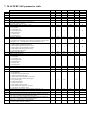
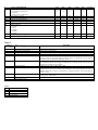
MASTERCASE parameter table......................................................................................................................................................39
Note 1........................................................................................................................................................................................................42
Meaning........................................................................................................................................................................................................42
Note 2 ..................................................................................................................................................................................................42
1. Introduction
MasterCase is the integrated system designed by Carel for the complete management of showcases. MasterCase controls and manages the entire
refrigeration unit, both electrically and electronically. The use of power relays means that MasterCase does not require an extra electrical panel, and
can directly control the lights, defrost heaters, fans, cooling actuators, and so on.
MasterCase can be connected to a local network to coordinate operations on a group of utilities, synchronising defrosts or sharing probes.
Furthermore, MasterCase can be integrated into the PlantVisor system, which saves and displays all the data on the operation of the unit.
MasterCase is available for the control of showcases with both mechanical expansion valves and in the version with "built-in" driver for the
management of proportional electronic expansion valves, which maximises the performance of the refrigeration unit.
The electronic valve optimises the evaporation temperature and superheating, and reduces the power consumption of the unit. Product conservation
quality and lower weight loss are ensured by the greater temperature stability and the reduced need for defrosts using MasterCase.
1.1 Main characteristics of the MasterCase
Power supply
230V alternating current.
Appearance and assembly
The dark plastic container, the narrow, stretched shaped, and the rear supports for DIN rail mounting, make this controller ideal for supermarkets and
for installation under the showcase. In addition, the 220Vac power supply and the relay outputs with voltage signals for the various loads (lights,
fans, defrost, etc.…) mean significant time savings for the wiring and assembly of the electrical panel, the controller itself featuring an integrated
electrical panel.
User interface
The user interface is from the series of standard PST terminals. This series, as well as being the same used by other Carel instruments (meaning a
reduction in the number of product codes), offers various solutions: display only, small terminal with 3 digits and 3 buttons, and large terminal with
4 digits and 8 buttons. Each button is backlit by a LED to signal the status of the unit (actuators on, alarms, etc...).
The terminals are not required for the operation of the MasterCase, but rather are used to program the controller. The terminals can be installed at a
distance of up to 10m from the instrument, and can be connected “live”, that is, when the instrument is on, without creating problems in operation.
Energy Savings - Advanced Software
Thanks to the numerous and innovative functions featured, the MasterCase not only controls all the various configurations of the showcases, but also
ensures considerable advantages in terms of energy savings. In fact, the use of the night-time set point, the possibility of different types of intelligent
defrosts, and the control of electronic expansion valves are just some of the functions that allow significant energy savings to be achieved.
Local network (LAN)
The MasterCase instruments can be connected together to create a LAN (Local Area Network), in Master-Slave configuration, for the control of
multiplexed showcases or multi-evaporator utilities. Each instrument can be configured as either the Master or a Slave by simply setting a parameter.
This configuration allows the synchronisation and coordination of defrosts, the propagation of the status of the digital inputs, as well as the display
on the Master of any alarms active on the Slaves. Up to 6 instruments (1 master and 5 slaves) can be connected together. The particularly reliable
structure of the LAN (16-bit CRC error checking) means the values read by the control temperature and/or pressure probe on the master can be
shared across the network, thus allowing a saving in the number of probes required. Finally, as regards the supervision software, the master acts as
the interface for the slaves, as only the master needs to be fitted with the serial card and connected to the RS485 line to be able to manage all the
instruments in the local network.
Alarm log
Each unit can save up to 10 alarms. Each new alarm is recorded in the log, deleting the oldest event if necessary.
RTC
The MasterCase can be fitted with an RTC card (with backup battery) for managing the defrosts at set times. In addition, this option allows the use of
other functions, such as the setting of a night-time set point starting and ending at set times, the saving of the age of the event in the alarm log, and so
on.
Third probe
This is used to measure the temperature at the hot point of the showcase and is used to help determine the reference control
temperature. In addition, it can be used to manage the defrost function on a second evaporator.
Duty setting
This function allows the utility to be operated even when there is a control probe fault. In these cases, operation will continue for a
time (in minutes) equal to the value set for the parameter “duty setting” (c4), with a fixed off time of 15 minutes.
Multifunction output
The auxiliary outputs (Aux1 and Aux2) are programmable and can duplicate the function of any of the outputs already present. In
addition, they can be used as alarm outputs or hot wire outputs, and can be configured as additional defrost outputs that are
independent of the standard defrost output, associated with probe 3.
Multifunction input
A total of five programmable digital inputs are available (see the list of parameters). These allow numerous possibilities, such as the enabling of
defrosts, the management of immediate or delayed alarms, the control of a door switch, etc.... In addition, a digital input known as the virtual input
can be configured, which is not physically connected but rather managed via the local network (for further details see the corresponding paragraph
further on).
Continuous cycle
The continuous cycle function allows the utility controlled to be forced on for a time set by parameter. This function may be useful
when requiring a rapid reduction in temperature, even below the set point.
In-circuit testing
The MasterCase series is manufactured using the most advanced SMD technology. All the controllers undergo “in-circuit testing” to
check the components installed. These tests are performed on 100% of the products.
Probes
The instruments are designed to operate with NTC probes, as these offer greater precision across the rated operating range. The
pressure probes used are ratiometric. All the probes are supplied by Carel.
Electronic valve
An optional card soldered directly onto the main board of the MasterCase (version MGE0000020) can be used to control the operation
of an electronic expansion valve with stepper motor. This allows the possibility to directly control the injection of refrigerant into the
evaporator. Consequently, lower and more stable superheating values can be achieved, as well as a higher evaporation temperature
and consequently higher humidity and a more constant temperature in the showcase, guaranteeing better conservation and quality of
the products.
Watchdog (Surveillance)
This device prevents the microprocessor from losing control of the unit even in the presence of significant electromagnetic
disturbance. In the event of abnormal operation, the watchdog re-establishes the initial operating status.
Electromagnetic compatibility
The instruments comply with the EU standards on electromagnetic compatibility.
CE mark and ISO 9001 certification
The quality and the safety of the MasterCase series instruments are guaranteed by Carel's ISO 9001 certified design and production
system, and by the CE mark on the product.
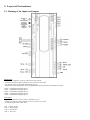
2. Layout of the hardware
2.1 Meaning of the inputs and outputs
Digital Inputs
- inputs from voltage-free contacts, with 8mA closing current
- connection with removable terminals for wires from 0.25 to 2.5mm2 .
- max distance 30m for standards compatibility (surge)
- the function of the digital inputs can be programmed using the parameters (multifunction inputs)
G-DI1 => Multifunction digital input 1
G-DI2 => Multifunction digital input 2
G-DI3 => Multifunction digital input 3
G-DI4 => Multifunction digital input 4
G-DI5 => Multifunction digital input 5
NTC sensors
- inputs for standard Carel NTC probes (10 Kohm at 25 °C)
- connection with removable terminals for wires from 0.25 to 2.5mm2
- maximum length of the cables 30m
G-S1 => Room probe
G-S2 => Defrost Probe
G-S3 => Third Probe
G-S4 => Not used
P.C. (condensing pressure ) Currently not supported
Evaporator Fan
L => Line
N => Neutral
4A 250Vac (Inductive Load)
Light
L => Line
N => Neutral
1000VA 250Vac (fluorescent tube)
Compressor
L => Line
N => Neutral
12 (12)A 2HP 250Vac (Inductive Load)
Defrost
L => Line
N => Neutral
12A 250Vac (Resistive Load)
230Vac
- Power supply input from mains to two removable screw terminals, with max 12A current rating
- minimum recommended cross-section of the wires from 1.5 to 2.5mm2.
L => Line
N => Neutral
230 Vac +10/-15% 50/60 Hz
230 Vac +10/-15% 50/60 Hz
Alarm
C => Common
NO => Normally Open (Free Contact)
NC => Normally Closed
12A 250Vac (Resistive Load)
Rail Heat (AUX2)
L => Line
N => Neutral
12A 250Vac (Resistive Load)
AUX Auxiliary (AUX1)
L => Line
N => Neutral
12A 250Vac (Resistive Load)
Note for all outputs:
- removable screw terminals for wires with a cross-section from 0.25 to 2.25mm2
Valve
- maximum length of the cables 10m
1 RED
W1
3 GREEN
2 WHITE
W2
4 BLACK
Valve Motor
Battery
B+ => Positive 24Vdc
B- => Negative
24Vac (0.5 Ampere)
~ => To 24Vac transformer output
~ => To 24Vac transformer output
NTC SH
G-Tsh => NTC superheating sensor
P.E. (evaporation pressure)
- for distances over 10m use shielded cables (2 wires plus shield connected to earth)
G => Ground
P => Input signal
Vp => Power supply
RS485 driver (Currently not supported )
PWM (Currently not supported )
Supervisor (network)
- Connector for optional card with RS485 driver for interfacing with the supervisor
- removable screw terminals for wires with cross-section from 0.25 to 2.25mm2.
- serial speed envisaged 19200 bit/sec
G => Ground
T+ => Connect to positive Carel Supervisor RS485 serial line
T- => Connect to negative Carel Supervisor RS485 serial line
Terminal
- three wire serial connection, maximum length 10m
- power supply supplied by the controller, 24/35Vdc 1.5W max.
Vs => Power supply
T+ => Data signal
G => Ground
LAN (Local Area Network)
- network connection to other controllers, max. length 10m
- removable screw terminals for wires with cross-section from 0.25 to 2.25mm2.
T+ => Data signal
G => Ground
PROGRAMMING KEY
The programming key should only be used when the controller is disconnected from the power supply (220Vac terminals not live),
and with the valve driver card powered (24Vac power supply terminals).
The product code of the programming key is PSOPZKEY00.
For details on how to use the key refer to the corresponding instruction sheet.
2.2 Codes of the models and accessories
CODES
DESCRIPTION
MGE0000000
MGE0000020
MGEOPZSER0
MGEOPZCLK0
PSOPZKEY00
MGECON0000
MGECON0020
MasterCas e
MasterCase with built-in electronic valve driver
Optional card for RS485 serial connection
Optional clock card (RTC)
Hardware programming key
Connector kit for MasterCase MGE0000000
Connector kit for MasterCase Valve MGE0000020
PST00VR100
PST00SR300
PST00LR200
PSTCON0300
PSTCON1000
SMALL red display
SMALL red terminal
LARGE red terminal
3m connection cable
10m connection cable
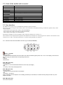
2.3 User interface
The MasterCase uses the series of standard PST terminals as the user interface.
This series, as well as being the same used by other Carel instruments (consequently allowing a reduction in product codes), offers
various solutions:
- small terminal with 3 digits and 3 buttons (code PST00SR300);
- large terminal with 4 digits and 8 buttons (code PST00LR200);
- remote display with 3 digits (code PST00VR100).
Each button is backlit by a LED to signal the status of the unit (outputs active, alarms, etc...).
The terminals are not required for the operation of the MasterCase, but rather are used to program the controller. The terminals can be
connected “live”, that is, when the instrument is on, without creating problems in operation.
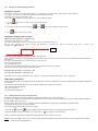
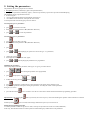
2.3.1 Functions of the buttons and LEDs on the PJ Large Terminal (PST00LR200)
Button • (red LED)
Normal operation
• pressed for 5 seconds deletes the HACCP alarm and resets the related signals (codes “HA” or “HF” on the display, the buzzer and
the alarm relay) and deletes all the corresponding data saved.
LED
on steady
HACCP alarm.
Button
(yellow LED)
Normal operation
• Pressed for 1 second activates/deactivates the AUX1 relay output (light)
LED
• on steady - AUX1 relay output (light) active
Button
(green LED)
Normal operation
• Pressed for 5 seconds switches the unit ON/OFF.
LED
• On steady - controller on
Note: the ON/OFF function depends on an enabling parameter (if not enabled, the controller is always ON), the LED in any case
displays the status.
Button
(yellow LED)
No function associated.
Button
(green LED)
Normal operation
• Pressed for 5 seconds activates or deactivates the continuous cycle.
LED
• on steady - continuous cycle on.
Button
(green LED)
Normal operation
• Pressed for 1 second switches the light on or off
• pressed together with button 8 displays the value of the third probe (S3)
• pressed together with button 7 for 5 seconds activates or deactivates the continuous cycle
Parameter programming
• Moves from one parameter to the next.
• Increases the value of the parameter displayed.
LED
• On steady - compressor on
• Flashing - compressor activation request in progress (cooling request)
Button
(yellow LED)
Normal operation
• Pressed for 5 seconds starts a manual defrost, if the conditions are right.
• pressed together with button 6 for 5 seconds activates or deactivates the continuous cycle
• pressed together with button 8 displays the value read by the end defrost probe (S2)
• Pressed together with button 8 when starting the controller loads the default parameters.
Parameter programming
• Moves from one parameter to the previous.
• Decreases the value of the parameter displayed.
LED
• on steady - defrost on
• Flashing –defrost request in progress.
Button
(red LED)
Normal operation
• Mutes the audible alarm (buzzer) and deactivates the alarm relay, if active.
• Pressed for 1 second displays and/or sets the set point
• Pressed for more than 5 seconds, when no alarm is present, accesses the menu of the type F parameters (frequent)
• pressed together with button 6 displays the value read by the third probe (S3)
• pressed together with button 7 displays the value read by the end defrost probe (S2)
• Pressed together with button 7 when starting the controller loads the default parameters.
Parameter programming
• Displays the value of the selected parameter or exits the display.
• Pressed for 5 seconds permanently saves the modifications made to the parameters.
LED
• on steady - alarm active.
2.3.2 Functions of the buttons and LEDs on the PJ Small Terminal (PST00SR300)
As regards the PJ Small terminal, the functions of the buttons are the same as seen for buttons
,
and
on the PJ Large terminal.
3. Installation
3.1 Electrical connections
For details on the electrical connections to the main board, see the layout shown above.
WARNINGS
Avoid installing the controllers in environments with the following characteristics:
1. Relative humidity greater than 85%, non-condensing
2. Heavy vibration or shocks
3. Exposure to continuous water sprays
4. Exposure to corrosive or pollutant gases (e.g. sulphur or ammonia fumes, saline mist, smoke) so as to avoid corrosion and oxidisation
5. Strong magnetic and/or radio interference (therefore avoid installing the unit near transmitting antennae)
6. Exposure of the controllers to direct sunlight or the elements in general.
The following warnings must be heeded when making the connections during the pre-installation of the controllers:
1. The incorrect connection of the power supply may seriously damage the system.
2. Separate the probe signal and digital input cables as much as possible from the power and inductive load cables, to avoid possible electromagnetic
disturbance. Never lay the power cables and the probe cables in the same channels. Avoid installing the probe cables in the immediate vicinity of power
devices (thermal magnetic circuit breakers and the like). Reduce the path of the probe cables as much as possible, and avoid paths that surround power
devices. Only use IP67 sensors for the end defrost probe; position the probes with the bulb placed vertically to assist the draining of any condensate.
Remember that the thermistor temperature probes (NTC) have no polarity and therefore can be connected in either order.
3. If a connection to the supervisory network is envisaged, connect the shield of the 485 cable to the 485 ground on the instrument.
4. In the MGE0000020 models, if a series of units are installed in the same electrical panel, do not supply the 24Vac from a common transformer,
but rather use a different transformer for each MasterCase.
5. The secondary of the transformers must not be earthed.
3.2 Configuring the controllers
3.2.1 Parameters relating to the hardware
When configuring an instrument that has just be installed, there are a number of parameters that are strictly related to the hardware connections.
These parameters are:
A1, A2,…, A5: configuration of the digital inputs;
/A: presence of the probes;
/4: virtual control probe (determines which probe is used for the control functions)
/7: presence of the remote display (determines the presence of the device and which probe is displayed on the remote display)
H5, H6: configuration of the auxiliary outputs;
P1(*): type of valve;
PI(*): type of pressure sensor;
PH(*): type of refrigerant used in the system.
(*) only for models with the electronic valve control, code MGE0000020
For the meaning and configuration of the parameters, see the corresponding section further on in the manual.
3.2.2 Stand-alone, local network (LAN) and supervisor configuration
There are three fundamental parameters used to configure an instrument for operation in a network (LAN or supervisor) or stand-alone operation: In,
H0 and Sn.
In defines the unit as the Master (In = 1) or a Slave (In = 0);
H0 represents the address of the instrument in the supervisor network for the Master or in the LAN for the Slaves;
Sn represents the number of Slaves present in the LAN (only set on the Master).
For the Master:
• the parameter “In” must be set to 1;
• the parameter “Sn” (Slave number): from 1 to 5, depending on the number of Slaves in the LAN;
- the parameter H0 (Serial address), in the event of connection to a supervisor network, must be set to a value equal to the sum of the address of the
previous master plus its number of slaves plus one, that is:
H0 = H0_Prev_Master + Sn_Prev_Master + 1 (Fig. x.x.x)
When switching the instrument on, the display will show “uM”, Master unit.
If the instrument is fitted with the RTC card, the following parameters also need to be set:
• parameters “td”, “th”, “t'”: weekday, hour, minute.
• parameters ”dx“, “hx”, “mx” with x = 1, 2,..., 10: days, hours and minutes corresponding to the defrost times, with 1 minute resolution.
For the Slaves:
• the parameter “In” must be set to 0;
• parameter “H0”: address of the slave in the LAN.
When switching the instrument on, the display will show “uSx” (x = 1..5 = value of “H0”).
3.2.3 Selecting the main operating parameters
Setting the set point
The set point (parameter “St”) is the main parameter, as it represents the reference value for the operation of the instrument.
It is simple to access and set, and this is done separately from the other parameters.
The default set point of the instrument is -20ºC.
If this value is not compatible with the application, it can be modified as follows:
•
press the
button for one second to display the current set point.
The value flashes;
•
increase or decrease the set point using the
•
press
and/or
buttons until reaching the desired value;
again to confirm the new value.
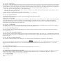
Parameters relating to the set point
Differential (control hysteresis) – parameter “rd”
The default of this parameter is 2 degrees.
The value is “RELATIVE”, that is, it is related to the set point, being added to this value.
The set point represents the point at which the instrument is switched off, while the activation point (On) is equal to the
set point (St) + differential (rd):
OFF
Temperature alarm thresholds – parameters “AH”, “AL” and "Ad"
These parameters are used to set the temperature thresholds above which the alarms are activated (activation of the alarm relays and the buzzer on
the terminal).
The values of these parameters are also “RELATIVE” to the set point.
AH: high temperature alarm;
AL: low temperature alarm;
Ad: delay time from when the threshold is exceeded to the activation of the alarm, in minutes.
The actual temperature thresholds are determined as follows:
high temperature threshold = set point (St) + AH;
low temperature threshold = set point (St) - AL;
The default values of these parameters are AH = 0 and AL = 0 (alarms not enabled), and the delay is Ad = 120 minutes.
Main defrost parameters
If the instrument is used for managing the defrost function, a number of parameters need to be checked when starting the instrument,
in particular:
• dI: interval in hours between defrosts (if set times with the RTC option are not used);
• dP: maximum defrost duration;
• d0: type of defrost;
• dt: end defrost temperature.
3.2.4 Loading the default values of the parameters.
During the installation of the instruments the operating parameters may be set incorrectly.
In other cases, significant electromagnetic disturbance may cause errors on the instrument when saving the data, with the display of
the error “EE” (data saving error).
In these and in other cases it may be useful to reset the instrument by assigning the parameters the default values.
To perform this operation, proceed as follows:
• disconnect the instrument from the power supply;
• press the Set
and Down
buttons together and switch the instrument on, keeping the buttons pressed;
• when the display shows the combination of characters “-- 3”, the buttons can be released.
At this point the instrument is automatically rebooted and is ready to operate correctly.
NOTE: If the error “EE” occurs quite frequently, the controller should be checked as the memory may be compromised and the
initial precision not guaranteed.
4. LAN functions
The MasterCase instruments can be connected together to create a LAN (Local Area Network), in Master-Slave configuration. The main purpose of
the LAN is to allow communication between as series of instruments (maximum six: one Master and five Slaves) with synchronised operation, for the
control of multi-evaporator utilities, such as multiplexed showcases. Each instrument can be configured as either the Master or a Slave by simply
setting a parameter. This configuration allows the synchronisation and coordination of defrosts, the propagation of the status of the digital inputs, as
well as display on the Master of any alarms active on the Slaves. The particularly reliable structure of the LAN (16-bit CRC error checking) means
the values read by the control temperature and/or pressure probe on the master can be shared across the network, thus allowing a saving in the
number of probes required. Finally, as regards the supervision software, the master acts as the interface for the slaves, as only the master needs to be
fitted with the serial card and connected to the RS485 line to be able to manage all the instruments in the local network.
4.1 Network defrost in multiplexed installations
One of the functions that most requires synchronisation is the defrost function. The Master controls the defrosts on all of the Slaves connected. It
waits for the defrost to be completed on all of the units before sending the end network defrost signal. The Slaves that have completed the defrost
must wait for the end defrost signal from the Master before switching to the dripping phase. Once the end defrost signal is received, the Slaves go
into dripping mode.
The defrost on each single unit and the network defrost are in any case stopped after the maximum defrost time, set using the parameter (“dP”,
default 30 min.).
The network defrost is performed cyclically, at a programmable interval set for the parameter dI. It can also be started:
- manually (pressing
for 5s on the Master);
- at set times (if the RTC option is present).
4.2 Remote alarm signals.
The unit configured as the Master in a LAN can signal remote alarms present on the Slave units, if enabled by setting the corresponding
configuration parameter (parameter Ar = 1). All the Masters are enabled for this function as default.
If a terminal or display is not essential for the operation of the unit, and indeed in a LAN the Slave can operate perfectly without such user interface,
this function is particularly useful for “centralising” the alarm management functions on the Master.
If the Master detects an alarm on a Slave unit (probe error, high or low temperature error, etc....), the display shows the signal “nX” (alternating with
the display of the temperature) where X = 1, 2, 3, ... 5, the LAN address of the Slave in question. When the event occurs, the alarm relay on the
Master is activated. The “nX” signal on the Master unit can be inhibited for one minute by pressing
.
4.3 Transmission of signals and probe readings
The particularly reliable and fast structure of the LAN (16-bit CRC error checking) allows the value read by the control probe and/or pressure probe
to be sent across the network, allowing savings in terms of both materials installed and installation time.
The transmission of the pressure probe signal must be enabled on the Master using the parameter “PA”, and the Slave must be enabled to receive the
signal suing the parameter “Pb”.
The control probe temperature sent by the Master is set on the Slaves by setting parameter “/A”=4.
5. Setting the parameters
The parameters have been grouped into two families:
• Frequent parameters (indicated by type F in the parameter tables)
• configuration parameters (indicated by type C), with access protected by a password to prevent unwanted tampering.
The parameters can be programmed as follows:
• from the keypad
• via LAN (download parameters from the Master to the Slaves)
• via an RS485 serial connection, if the optional card is fitted.
To set the parameters from the keypad, proceed as follows.
Accessing the type “F” parameters
•
•
press
for more than 5 seconds;
the display shows the parameter “PP” (Parameter Password);
•
press
and
to scroll the parameters.
Accessing the type “C” parameters
•
•
press
for more than 5 seconds;
the display shows the parameter “PP” (Parameter Password);
•
press
•
press
•
•
confirm by pressing
.
the display shows the parameter “PP” again;
•
press
;
or
or
until displaying 22 (password to access the type “C”) parameters;
until displaying the parameter to be programmed.
Modifying the parameters
After having displayed the first parameter, either type C or type F, proceed as follows:
•
press
•
press
•
modify the value by pressing
or
until reaching the parameter to be programmed;
to display the value associated;
and/or
;
• press
to temporarily confirm the new value and return to the display of the parameter code;
• repeat all the operations in the point “Setting the parameters” to modify the values of other parameters.
Saving the new values:
•
press the SET button
for five seconds to save the new value/values entered and exit the Parameter programming procedure.
Important note: only pressing the
off before pressing
button permanently saves the temporary values entered during the operation. If the instrument is switched
for five seconds, all the changes made and temporarily saved will be lost.
Exiting the programming procedure
To exit the procedure without saving the new values, do not press any button for at least 30 seconds (TIMEOUT).
In this way, the instrument returns to normal operation without making any modifications to the parameters.
5.1 Classification of the parameters
The parameters, as well as being divided by TYPE, are grouped into logical categories identified by the first letter or symbol. The following table
shows the categories and the corresponding letters/symbols.
Letter/Symbol
/
r
c
d
A
F
H
t
P
Category
temperature probe management parameters
temperature control parameters
safety and control activation time parameters
defrost management parameters
alarm management parameters
evaporator fan management parameters
general configuration parameters (addresses, enabling of the functions, etc…)
clock and HACCP parameters
electronic valve management parameters
5.2 “Password” parameters
PP: access level password
The first parameter encountered when entering programming mode is a “password” parameter that allows access to all the parameters of the
instrument; if the password is not entered, only the type “F” parameters can be accessed. This prevents access to the “C” parameters by unauthorised
persons. Once having accessed the configuration parameters, the type “F” parameter can also be modified.
The procedure for accessing and modifying the parameters is described above.
PS: alarm log password
• after having reached the parameter “PS” (Password Log).
• enter 44 as the password for accessing the alarm log
•
press
for more than 5 seconds to access the log.
ALARM LOG
All models of the MasterCase series feature an alarm log that saves up to 10 events. The models fitted with RTC also allow “the age” of each alarm
to be saved, that is, the time in hours that has elapsed from when the alarm was recorded to when the log is accessed.
The following events are saved in the log:
• the high and low temperature alarms (“HI”, “LO”);
• the control probe error (“rE”);
• the end defrost probe error (“E2”);
• the defrost by temperature ended by timeout signal, if enabled as an alarm (“Ed”);
• the loss of LAN communication by a controller in network, either the Master or the Slaves (“MA” and “uSx”).
Accessing the display of the log
The alarm log is displayed by entering the value 44 for the password parameter “PS” (Log Password) and confirming by pressing the Set button for
5 seconds.
Description of the alarm log
If the alarm log is empty, the display shows three bars (\\\), otherwise the following information is displayed in sequence:
• the index of the alarm in the log, preceded on the left by a graphic symbol;
• the code of the alarm;
• the time elapsed in hours (only for units fitted with RTC) since the event was saved.
If the RTC option is not present, the graphic symbol “_ _ _” is displayed instead of the time.
The three displays are shown cyclically in succession. In the log is scrolled by pressing the arrow buttons:
•
to display the older alarms
•
to display the more recent alarms.
The log can save 10 events.
The alarms appear in the log in the order they were saved in.
When a new alarm is saved, the older alarms are moved back a position in the list. If the log is full, the new alarm deletes the oldest alarm (FIFO
logic: First In First Out).
If an alarm has been present in the log for over 199 hours, its age is replaced by the graphic symbol “_ _ _”.
NOTE: If the current time value is lost on the instrument, the display shows “tC” and the age of all the alarms saved is replaced by the graphic
symbol “_ _”.
Exiting the log
To exit the display of the log, press
for one second, or alternatively do not press any button for 30 seconds.
Deleting the log
The alarm log can be deleted by pressing and holding
controller will exit the display of the log.
and
together for 5 seconds when the log is displayed. At the end of the operation the
Pd: download password
• after having reached the parameter “Pd” (Download Password).
• enter 66 as the password on the Master unit with Slaves connected to download the parameters from the Master to the Slaves during the
configuration of a multiplexed island
• press
for more than 5 seconds to start the download.
When the temperature is displayed again the download is complete.
DOWNLOAD PARAMETERS
All the MasterCase series instruments feature the possibility of transferring the values of the parameters from the Master to the Slaves via the LAN.
This operation saves time when programming instruments in the same LAN with similar settings.
The table below lists the parameters that can be transferred via LAN from the Master to the Slaves.
TABLE OF DOWNLOADABLE PARAMETERS
CODE
St
/4
/6
/7
/9
/A
/t
rd
r1
r2
r3
r4
r5
r6
c0
c4
c6
cc
d0
d2
d3
d4
d5
d6
d7
d8
d9
dd
dI
dP
dt
A0
A7
Ad
AH
AL
F0
F1
F2
F3
Fd
H1
H3
H4
DESCRIPTION
Control probe Set Point
Virtual probe (%)
Enable decimal point to display the temperature
Remote display management
Use third probe as end defrost probe
Presence of probes
User interface management
Control differential
Minimum temperature setting
Maximum temperature setting
Enable defrost ended by timeout signal
Variation between daytime and night-time set point and vice-versa
Enable Max and Min temperature monitoring
Enable night-time control with the third probe
Start compressor delay from controller on
Compressor on time in Duty Setting operation
Low temperature alarm bypass time after continuous cycle
Continuous cycle duration
Type of defrost
Type of control for local network defrost
Compressor on time with temp. < 1°C before starting defrost
Defrost when switching the instrument on (YES/NO)
Defrost delay when switching the instrument on
Management of the terminal display and remote display during the defrost
Enable skip defrost based on defrost duration
Alarm bypass time after defrost
Defrost priority over compressor safety
Dripping time
Interval between defrosts
Maximum defrost duration
End defrost temperature
Fan alarm differential
Digital input reading delay time
Delay in reading high and low temperature alarms
High temperature alarm upper band
Low temperature alarm lower band
Fan management (always on or slave to the fan controller)
Fan set point
Fans off when compressor off
Fans off in defrost
Fans off in post-dripping
Enable / disable remote control
Enable ON – OFF from keypad
Enable ON – OFF from supervisor
Download failed signals
The Master displays the failure of the download to a Slave by showing the signal (alternating with the temperature) “dx”, where x = 1, 2, ..., 5, that is,
the value of the parameter “H0” corresponding to the Slave on which the “data transfer” via LAN operation failed.
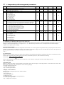
5.3 / = temperature probe management parameters
/
/2
/4
/6
/7
/8
/9
/A
/C
/d
/t
PROBE PARAMETERS
Measurement stability
Virtual probe (between probe 1 and probe 3)
(0 = probe 1; 100 = probe 3)
Enable decimal point (0 = No, 1 = Yes)
Remote display management
0 = not present
1 = room probe (S1)
2 = defrost probe (S2)
3 = third probe (S3)
4 = virtual probe
5 = terminal probe
3rd probe calibration
Defrost also with probe 3:
1 = the defrost by temperature ends when the temperature detected by
probe 2 and probe 3 are the temperature set for the parameter “dt”
Probes present
0 = defrost probe and third probe absent
1 = defrost probe absent and probe 3 present
2 = defrost probe present and probe 3 absent
3 = both defrost probe and probe 3 present
4 = control probe from master
Control probe calibration
Defrost p robe calibration
User interface management
0 = not present
1 = room probe (S1)
2 = defrost probe (S2)
3 = third probe (S3)
4 = virtual probe
5 = terminal probe
Type
C
Min.
1
Max.
15
UOM
-
Def.
1
To LAN
C
0
100
-
0
•
C
0
1
flag
1
•
C
0
5
-
0
•
C
-20.0
20.0
°C
0.0
C
0
1
flag
0
•
C
0
4
-
0
•
F
C
-20.0
-20.0
20.0
20.0
°C
°C
0.0
0.0
C
0
5
-
4
•
/C: calibration or calibration offset of the room probe (S1)
The value assigned to this parameter is added to (positive value) or subtracted from (negative value) the temperature measured by probe S1. For
example, to decrease the temperature by 2.3 degrees, set /C = -2.3. The offset may be set from -20 to +20 with precision to the tenth of a degree.
- Default: 0.0 (no offset to probe reading).
/2: measurement stability
Defines the coefficient used to stabilise the temperature measurement. Low values assigned to this parameter offer a prompt response of the sensor to
variations in temperature; the reading is however more sensitive to disturbance. High values, on the other hand, slow down the response but
guarantee greater immunity to disturbance, meaning a more stable reading.
- Def.: 1.
/4: virtual probe:
Defines a non-existent probe used for the normal control functions This parameter determines the weighted average used to calculate the reference
control probe value based on the reading of the room probe (S1) and the third probe (S3). The formula is the following:
virtual probe =
(100 − ("/4")) xS1 + ("/4") xS 3
;
100
If set to 0, the virtual probe coincides with the room probe (S1); if set to 100, the virtual probe coincides with the third probe (S3).
- Def.: 0, room probe (S1).
/6: decimal point
Enables or disables the display of the temperature with resolution to the tenth of a degree, in the range between -9.9 and 99.9 for the version with
Small display, and between -99.9 and 999.9 for version with Large display.
0 = display without decimal point;
1 = display with decimal point.
- Def.: 1, decimal point enabled.
/t: display on user interface
Selects the probe reading displayed on the interface terminal
0 = Not present
1 = Room probe (S1)
2 = End defrost probe (S2)
3 = Third probe 3 (S3)
4 = Virtual control probe (depends on the parameter /4)
5 = Terminal probe (if present)
- Def.: 4, displays the virtual probe.
/7: display on remote display
Selects the probe reading displayed on the remote display
0 = Not present
1 = Room probe (S1)
2 = End defrost probe (S2)
3 = Third probe (S3)
4 = Virtual control probe (depends on the parameter /4)
5 = Terminal probe (if present)
- Def.: 0, display not present.
/8: third probe calibration
The value assigned to this parameter is added to (positive value) or subtracted from (negative value) the temperature measured by probe S3. For
example, to decrease the temperature by 2.3 degrees, set /8 = -2.3. The offset may be set from -20 to +20 with precision to the tenth of a degree.
- Default: 0.0 (no offset to probe reading).
/9: defrost with probe 3
This parameter allows the third probe S3 to be used as the end defrost probe together with probe S2. In this case, the defrost by temperature ends
when the temperature measured by both the probes is greater than or equal to the end defrost temperature (see parameter “dt”). Consequently, probe
3 can be used as a defrost probe on a second evaporator.
- Def.: 0.
/d: end defrost probe calibration (S2)
The value assigned to this parameter is added to (positive value) or subtracted from (negative value) the temperature measured by probe S2. For
example, to decrease the temperature by 2.3 degrees, set /C = -2.3. The offset may be set from -20 to +20 with precision to the tenth of a degree.
- Default: 0.0
/A: probes present
The value of this parameter tells the instrument whether the probes S2 and/or S3 are connected. The value of 4 only makes sense on controllers
configured as slaves as, with this setting, the slaves no longer uses their own probes for the control functions, but rather use the probe reading sent by
the master.
Do not set the value to 4 on a controller configured as the Master.
The possible values of this parameter are as follows:
0 = defrost probe and third probe absent
1 = defrost probe absent and probe 3 present
2 = defrost probe present and probe 3 absent
3 = both defrost probe and probe 3 present
4 = control probe from master (slaves only).
The room probe (S1) is always considered as being present.
- Def.:0.
5.4 r = temperature control parameters
r
r1
r2
r3
r4
r5
r6
rd
rH
rL
rt
CONTROL PARAMETERS
Minimum temperature setting
Maximum temperature setting
Enable Ed alarm (defrost ended by timeout)
0 = No, 1 = Yes
Automatic variation of the night-time set point
(curtain switch closed)
Enable min. and max. temperature monitoring
0 = No; 1 = Yes
Night-time variation with third probe
(1 = night-time with curtain lowered, control with probe 3;
0 = night-time control with the virtual probe)
Control differential (hysteresis)
Max. temperature measured in the interval “rt”
Min. temperature measured in the interval “rt”
Min. and max. temperature monitoring time
Type
C
C
Min.
-50.0
r1
Max.
r2
90.0
UOM
°C
°C
Def.
-50.0
90.0
To LAN
•
•
C
0
1
flag
0
•
C
-20
20
°C
3.0
•
C
0
1
flag
0
•
C
0
1
flag
0
•
F
F
F
F
0.1
0
20.0
999
°C
°C
°C
hours
2.0
-50
90
0
•
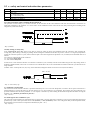
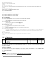
rd: differential
Determines the value of the temperature control differential. Operation can be defined as follows:
temperature > set point + diff. (rd) à control on
temperature set point à control off
This is also shown in Figure xx.
Direct (cooling)
rd
on
actuator
off
Set point
Fig. xx
- Def.: 2.0.
r1: Minimum temperature setting
Determines the minimum value that can be set for the set point. This parameter prevents the user from setting a set point that is lower than the
corresponding value.
- Def.: -50.0.
r2: Maximum temperature setting
Determines the maximum value that can be set for the set point. This parameter prevents the user from setting a set point that is higher than the
corresponding value.
- Def.: 90.0.
r3: enable end defrost by timeout signal
Enables the signal indicating the end of the defrost after the maximum time, set for the parameter “dP”, using the code “Ed”.
0 = signal disabled
1 = signal enabled
- Def.: 0.
r4: set point variation
The value set for this parameter will only be effective if the parameter “Stn” is set to 1 or 2. In this case, the set point will change either when a
digital input configured as the “curtain switch” is closed (see parameters A1…A5 = 7), or at a set time if the controller is fitted with the RTC option
(see parameters “hSn” and “hSd”). The set point varies by the value with sign saved for the parameter “r4”, as follows:
new_set point = set point (“St”) + “r4”
- Def.: 3.0.
r5: enable temperature monitoring
Enables temperature monitoring, recording the maximum (“rH”) and minimum (“rL”) temperatures reached in the interval “rt” (max
999h).
r5 = 0: temperature monitoring disabled
r5 = 1: temperature monitoring on probe S1 enabled
The monitoring starts from when “r5” is assigned the value 1.
To disable temperature monitoring, set “r5” to 0. After 199 hours, the maximum monitoring time allowed by the instrument, the max.
and min. temperatures are no longer recorded. Set “r5” again to start a new monitoring cycle.
- Def.: 0.
r6: control with the third probe from digital input
This is used to move the temperature control to the third probe (S3) when a digital input configured as the “curtain switch” is closed (see parameters
A1…A5 = 7).
r6 = 0: no change, control by virtual probe
r6 = 1: when the digital input is closed, control is performed using probe S3
- Def.: 0.
rt: temperature monitoring time
Once the temperature monitoring function (parameter “r5”) has been enabled, this parameter records the time in hours from the start of the
monitoring cycle.
- Def.: read-only parameter, no default value.
rH: maximum temperature measured in the time “rt”
Once the temperature monitoring function (parameter “r5”) has been enabled, this parameter records the maximum temperature reached from the
start of the monitoring cycle.
- Def.: read-only parameter, no default value.
rL: minimum temperature measured in the time “rL”
Once the temperature monitoring function (parameter “r5”) has been enabled, this parameter records the minimum temperature reached from the
start of the monitoring cycle.
- Def.: read-only parameter, no default value.
5.5 c = safety and control activation time parameters
c
c0
c4
c6
cc
TIMES AND SAFETY PARAMETERS
Control start delay when switching the instrument on
Safety relay
0 = control always OFF
100 = control always ON
Low temp. alarm bypass time after continuous cycle
Continuous cycle duration
Type
C
C
Min
0
0
Max
15
100
UOM
min
min
Def.
0
0
C
C
0
0
15
15
hours
hours
2
4
c0: Control start delay when switching the instrument on
This parameter is used to delay, by a set time in minutes, for the activation of the control functions from when the instrument is switched on. In
multi-utility installations, the parameter “c0” can be used to avoid simultaneous starts of the various units, thus preventing the overloading of the
refrigeration system when starting.
- Def.: 0 (minutes).
c4: Duty setting or safety relay
If the “control probe error (rE)” alarm occurs (that is, probes S1 and/or S3 faulty), this parameter allows the controller to keep operating the
cooling utility, thus reducing or limiting any damage while awaiting the elimination of the fault. In practice, as there is no longer any temperature
control, the controller operates in cycles, with an ON time equal to the value assigned to the parameter “c4” (in minutes) and a fixed OFF time of 15
minutes.
Two values of c4 bring about specific situations:
c4 = 0: controller always OFF;
c4 = 100: controller always ON.
If control error occurs while the controller is in a defrost or continuous cycle, it instantly exits the current status and goes into “duty setting” mode. It
should be remembered that, in the event of a control error on a Master/Slave unit, local or manual defrosts and the continuous cycle functions are no
longer available.
A Master with a “control probe error (rE)” may, on the other hand, manage the defrosts on the slaves served (network defrost).
OFF=15 min.
c4
- Def.: 0, control always off.
cc: continuous cycle duration
This is the time in hours that the controller is operated continuously for so as to lower the temperature, even below the set point. This function is
started manually by pressing the buttons on the user interface. If cc=0, the continuous cycle is disabled. The controller exits the continuous cycle
procedure when the time set for the parameter “cc” has elapsed, or alternatively when reaching the minimum temperature threshold set using the
parameter “AL” (minimum_threshold=set point-AL).
- Def.: 4 (hours).
c6: alarm bypass after continuous cycle
This is the time in hours that the low temperature alarm is ignored, that is, not activated, after a continuous cycle. The low temperature alarm will be
generated only if, after a time equal to the sum of “c6” (in hours) + "Ad" (in minutes), where "Ad" is the general delay for the temperature alarm,
the temperature is still below the low temperature threshold (set point - “AL”).
- Def.: 2 (hours).
5.6 d = defrost management parameters
d
d0
d2
d3
d4
d5
d6
d7
d8
d9
dd
dI
dP
dt
dM
dPM
DEFROST PARAMETERS
Defrost type
0 = electric: ends at temperature and/or by timeout
1 = hot gas: ends at temperature and/or by timeout
2 = electric: ends by timeout
3= hot gas: ends by timeout
LAN defrost command type
0 = start only
1 = start and stop
Compressor running time with ambient temperature below 1°C before
forcing a defrost
Defrost when starting the instrument (0 = No, 1 = Yes)
Defrost delay when starting the instrument or from digital input
Interface module and remote display management during defrost:
0 = No display lock. The temperature alternates with the “dF” symbols
on both displays;
1 = Temperature locked on both displays
Enable skip defrost based on defrost time (0 = No, 1 = Yes)
High temperature alarm bypass time after defrost and if A4 = 5 or A8 =
5 alarm bypass time from door open
Defrost priority over compressor protection (0 = No, 1 =Yes)
Dripping time after defrost
Interval between two defrosts
Maximum defrost duration
Defrost end temperature
Time between two successive cleaning signals
Cleaning signal duration
Type
Min.
Max.
UOM
Def.
To LAN
C
0
3
-
0
•
C
0
1
flag
1
•
C
0
192
hours
0
•
C
C
0
0
1
180
flag
min
0
0
•
•
C
0
1
flag
0
•
C
0
1
flag
0
•
F
0
15
hours
1
•
C
F
F
F
F
C
C
0
0
0
1
-50.0
1
0
1
15
192
180
30.0
999
60
flag
min
hours
min
°C
hours
min
0
2
8
30
4.0
1
0
•
•
•
•
•
d0: type of defrost
Establishes the type of defrost:
0 = electric heater, end at temperature or after maximum safety time (timeout)
1 = hot gas, end at temperature or after maximum safety time (timeout)
2 = electric heater, end by timeout
3 = hot gas, end by timeout
- Def.: 0, electric heater defrost, end at temperature.
d2: Type of defrost control
Determines whether the instrument, in a LAN, at the end of the defrost waits for an end defrost signal or not.
“d2” = 0 the instrument completes the defrost without waiting for the end signal (stand-alone instrument);
“d2” = 1 the instrument waits, at the end of the defrost, for the end signal sent by the Master via the LAN of multiplexed showcase.
Def.: 1.
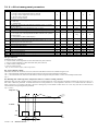
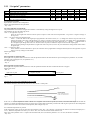
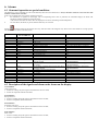
d3: Running time with evaporator temperature below 1°° C before starting a defrost.
Determines how long the controller operates (solenoid valve output/compressor active) when the temperature measured by probe S2 is below 1°C,
after which a defrost is performed. To disable this function set the parameter to 0. For temperature values above 1°C and/or when the controller is
inactive, the time is not counted. Obviously, the time is managed by an incremental counter that is set to zero only after the set value has been
reached and the corresponding defrost performed.
Def.: 5 (hours).
Temp. S2 °C
1°C
time
Control
ON
OFF
t1
t1 + t2 +… tn
d3à Start defrost
t2
time
d4: Defrost when switching the instrument on
Starts a defrost when the instrument is switched on. The possible values are:
0 = no, no defrost is performed when switching the instrument on;
1 = yes, a defrost is performed when switching the instrument on.
This function may be useful in cases where, due to frequent power failures and the consequent resetting of the defrost timer (see parameter “dI”), the number of
defrosts performed may be insufficient. In multi-utility systems, to avoid the simultaneous defrosting of all the units when power returns, set parameter “d5”,
corresponding to the defrost delay, to different values.
- Def.: 0.
d5: Defrost delay when switching the instrument on or from digital input
Represents the delay time in minutes before starting a defrost when the instrument is switched on (as set by parameter “d4”) or from a digital input (set with
parameters A1…A5 = 3 or 4).
- Def.: 0.
d6: user interface and remote display management during defrosts
During the defrosts, two types of behaviour can be set for the user interface and the remote display:
0 = display of the temperature, alternating with the symbol “dF” on both displays;
1 = both displays locked on the last value displayed before starting the defrost.
The display normally returns on both devices after the post-dripping phase (with normal control enabled).
- Def.: 0.
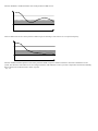
SKIP DEFROST
d7: enable “skip defrosts”
This parameter enables the algorithm by which, based on the actual time elapsed during the last defrost, the following defrost is performed or
skipped. The following rules are considered:
• the maximum number of consecutive defrosts that can be skipped is 3, that is, after the third defrost skipped, the following one is always performed;
• after switching the instrument on, the first 8 defrosts are always performed;
• the number of events to be skipped is increased by a maximum of 1 at a time;
• the manual defrosts (started on the user interface) or by digital input are always performed and counted;
• the function can only be used with the defrosts that end at temperature (“d0” = 0 or 1).
“d7” = 1 skip defrosts enabled; “d7” = 0 skip defrosts disabled.
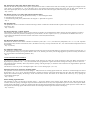
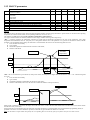
This function is based on a very simple but very effective principle. If the defrost lasts less than or equal to 65% of the time set for the parameter
“dP” (maximum defrost time), the next defrost envisaged will be skipped. When the following defrost is performed, the check is repeated, and if the
outcome is the same then the following two defrosts envisaged are skipped, and so on according to the criteria described above (maximum 3
successive defrosts skipped).
As soon as the defrost time exceeds 65% of the time “dP”, the following defrost will be performed and the function will start again.
The following is a graphic representation of the function.
Def
time
< 65%
Def
Def
Manual < 65%
The planned defrosts are skipped
time
< 65%
Defrosts skipped
time
< 65%
< 65%
The function starts over
Manual > 65%
- Def.: d7=0.
d8: Alarm bypass time after defrost and/or door open
Indicates the time the temperature alarm signal is ignored from the end of a defrost and/or after the switching of a digital input configured as the
“door switch” (see parameters A1…A5). In the latter case, it also indicates the maximum opening time for the door, in other words, after the set
time, if the digital input (door) is still open, the instrument will start the control functions again, with an alarm signal on the display.
- Def.:1 (hours).
d9: Defrost priority over safety and control activation times
Cancels the safety times set using the parameters in family “c” when starting the defrost.
0 = the safety times are observed;
1 = the defrost has greater priority and the times set using the “c” parameters are ignored.
- Def.: 0.
dd: dripping time
This parameter is used to set the time in minutes following a defrost in which the controller and the evaporator fans are stopped, so as to allow the
evaporator to drip.
- Def.: 2 (minutes).
dI: interval between “cyclical” defrosts
The parameter “dI” manages the so-called “cyclical” defrosts, in that they are repeated after the number of hours set for the parameter. The time is
reset every time a defrost is performed (including non-cyclical defrosts). If “dI” is equal to 0 (dI = 0), cyclical defrosts are disabled. In a LAN, a
cyclical defrost on the Master also starts a defrost on the Slaves connected (network defrost).
- Def.: 8 (hours).
dP: Maximum defrost duration
Determines the duration of the defrost in minutes for defrosts by time (“d0” = 0 or 1). For defrosts by temperature (“d0” = 2 or 3), “dP” represents
the maximum safety duration of the defrost, that is, the defrost will in any case stop after the time “dP”, even if the end defrost temperature has not
been reached.
- Def.: 30 (minutes).
dt: end defrost temperature
This parameter is used to set the evaporator temperature measured by probe S2 at which the defrost is stopped. If when a defrost is started (“d0” = 0
or 1) the temperature ready by S2 is greater than the value of “dt”, the unit goes directly into the dripping phase. If probe S2 is faulty, the defrost in
any case ends after a maximum time (parameter “dP”).
- Def.: 4.
CASE CLEANING MANAGEMENT
This function is used to manage the periodical cleaning of the showcase. By setting two specific parameters (“dM” and “dPM”) and selecting a
digital input (see parameters “A1”…”A5”), the instrument can be programmed to “signal” the need for cleaning and “oblige” the user to intervene.
The instrument enters “standby” status (only after the opening of the digital input), in which the control functions are stopped and the inputs and
outputs deactivated.
The function is active only if one of the digital inputs is set as a “case cleaning input” (“Ax”=10).
dM: time between two successive cleaning signals
This parameter is used to set the time in hours (range 1 - 1000) between one cleaning signal and the next. The time is counted starting from when a
digital input is set (“Ax” to 10) or when the instrument is switched on and one of the inputs has already been set to that value. When the time has
elapsed, the instrument displays the message “CCM” and the buzzer sounds. The buzzer can be muted in the normal way or by opening the
corresponding digital input.
- Def.: 1 (hours).
dPM: cleaning signal duration
This parameter is used to set the time in minutes (range 0 - 60) for the duration of the cleaning signal. When the time “dM” has elapsed, the
controller awaits the opening of the digital input associated with this function, and only if the input remains open for a time at least equal to “dPM”
will the signal on the display (“CCM”) be cancelled and, unless already deactivated manually, the buzzer muted. At this point, the counter “dM” will
start again for the following signal. Otherwise the buzzer will sound again and the signal will remain on the display.
- Def.: 0 (minutes).
5.7 A = alarm management parameters
A
A0
A1...5
A7
A8
Ad
AH
AL
Ar
ALARM PARAMETERS
Fan (see parameter F1) and alarm differential
Digital input configurations
Detection delay time for the “delayed alarm” input (An = 2)
Virtual digital input configuration
Temperature alarm delay
High temperature alarm: indicates the maximum variation from the set
point. AH = 0 disables the high temperature alarm
Low temperature alarm: indicates the maximum variation from the set
point. AL = 0 disables the low temperature
alarm
Slave alarm signal enabled on Master
(1=remote alarms enabled on Master)
Type
C
C
C
C
C
Min.
0.1
0
0
0
0
Max.
20.0
10
180
10
180
UOM
°C
min
min
Def.
2.0
0
0
0
120
To LAN
•
F
0
20.0
°C
0.0
•
F
0
20.0
°C
0.0
•
C
0
1
flag
1
•
•
A0: Fan and alarm differential
Represents the differential used to establish the temperature threshold for the deactivation of a high or low temperature alarm (“AL” and “AH”) (see
the figure below) and for the management of the fans (see parameter “F1”). In the case of the alarms, the value of A0 is used to determine the points
at which the temperature alarm is deactivated.
- Def.: 2.0.
AH: High temperature alarm
This value is related to the set point. It indicates the maximum deviation allowed from the set point above which a high temperature alarm is
activated, indicated by the code “HI” on the display and signalled audibly by the buzzer. In numerical terms:
Control temperature > Set point (“St”) + “AH” è
HIGH TEMPERATURE ALAR M
(“HI”)
Changing the set point therefore automatically changes the alarm threshold.
The point at which the alarm is deactivated is as follows:
Control temperature
Set point (“St”) + “AH” - “A0”
When the alarm condition is no longer present the corresponding audible signal and message the display are automatically cancelled.
- Def.: 0.0.
AL: Low temperature alarm
This value is related to the set point. It indicates the maximum deviation allowed from the set point set point below which a low temperature alarm is
activated, indicated by the code “LO” on the display and signalled audibly by the buzzer. In numerical terms:
Control temperature < Set point (“St”) - “AL” è
LOW TEMPERATURE ALARM
(“LO”)
Changing the set point therefore automatically changes the alarm threshold.
The point at which the alarm is deactivated is as follows:
Control temperature
Set point (“St”) - “AL” + “A0”
When the alarm condition is no longer present the corresponding audible signal and message the display are automatically cancelled.
It should be remembered that the low temperature alarm threshold is also used in the continuous cycle (see parameter “cc”) as the minimum value for
stopping the function.
- Def.: 0.0.
NOTE: the temperature alarms are not generated in the following cases:
- during a defrost;
- during the continuous cycle.
Ad: temperature alarm delay
Indicates after how many minutes the temperature alarm is signalled from when the corresponding alarm threshold has been exceeded. If the alarm
condition is longer present before the time "Ad" has elapsed, no alarm signal is generated.
The temperature alarm delay has no effect on two special functions: the defrost and the continuous cycle. To delay a temperature alarm after these
functions, use the parameters “d8” for the defrost and “c6” for the continuous cycle.
- Def.: 120 (minutes).
DIGITAL INPUT CONFIGURATIONS
The MasterCase series instruments feature five digital inputs that can be configured using parameters A1, A2, A3, A4 and A5 (following A1…A5)
respectively, associated with the inputs DI1 to DI5. In addition, a further parameter, “A8”, is used to manage a digital input called the “virtual” input,
as it is not physically present on the instrument, but rather associated with the status of digital input DI1 on the Master in a LAN (Master-Slave
configuration).
On a Master controller, the input will be associated with a specific signal from the Supervisor, otherwise parameter “A8” will have no function.
The functions corresponding to each value of A4…A5 / A8 are described below:
A1…A5 / A8 = 0: digital input disabled
The corresponding digital input is not used and ignores the closing/opening of any contacts connected to it.
A1…A5 / A8 = 1: input associated with an immediate external alarm
The digital input can be connected to an external alarm that requires immediate activation (for example, high pressure alarm, etc…). The alarm is
generated when the contact is opened, and causes the display of the code “IA”, the activation of the buzzer and the total shutdown of the controller
and all the related outputs. When the alarm condition is no longer present, the unit returns to normal temperature control operation.
A1…A5/A8 = 2: input associated with a delayed external alarm
The operating mode is the same as for value 1 above, in this case however the alarm signal can be delayed by a time, in minutes, equal to the value
set for the parameter “A7”.
A1...A5/A8 = 3: input associated with a defrost enabling signal
This setting is used to enable/disable the defrost function. When the contact is open the defrost is inhibited, when the contact is closed the defrost is
enabled. If the contact is closed, but there is no defrost request, the defrost is obviously not performed. If the contact is closed and a defrost is in
progress, when the digital input is opened the current defrost is stopped and the successive defrosts are inhibited, until the next time the digital
contact is closed.
Possible applications
This function is useful, for example, in the case of multiplexed showcases with hot gas defrost. In these systems, the defrosts are performed in
“islands” and therefore, at any one time, some islands are enabled to defrost, and others are disabled. Another use of the function is to prevent
defrosts on the units accessible to the public during opening times.
NOTE: the enabling/disabling of the defrost from a digital contact is effected locally. A Master, with A1...A5/A8=3 and with the corresponding
digital input open, may not defrost locally, while it may start the defrost on the units served (manual, cyclical or set time defrost).
A1...A5 /A8 = 4: input associated with an immediate defrost from external contact
When the corresponding digital input is closed, a defrost is started, according to the criteria set for the type “d” parameters.
Possible applications
This function is useful when defrosts need to be performed on a series of utilities coordinated by an external timer. To avoid simultaneous defrosts,
the parameter “d5” can be used to delay the start of the defrost on each unit. Another use of the function is to prevent defrosts on the units accessible
to the public during opening times.
NOTE: in the case of a Master with Slaves, when its own digital contact closes a network defrost will start, even if the Master will not defrost locally.
The following drawing explains the above function:
t
time
defrost
dP(1
d5(2
unit
defrost
dP(2
d5(3
unit
defrost
dP(3
unit
defrost
request
KEY:
t = impulse from the timer to start the defrost: the minimum duration must be 0.5 seconds
dP(1) = maximum defrost duration, unit 1
d5(2) = defrost delay from external contact for unit 2. This must be greater than dP(1), otherwise the defrosts will overlap.
Similar meanings for d5(3) and dP(3)
A1…A5 / A8 = 5: Door switch
This function is used to manage the door switch on a cold room. When the contact (door) is opened, the control functions and the fans are stopped and
the light output is activated. When the contact closes the unit starts again in the previous operating mode, delaying any temperature alarms for a number
of hours equal to the value of the parameter “d8”. If the door, and consequently the contact, remain open for a time greater than “d8”, the display shows
the alarm code “dr” and the controller returns to the operating mode it was in prior to the opening of the door. Specifically:
• if the controller was in Duty Setting mode, it returns to Duty Setting;
• if the controller was in continuous cycle mode, it returns to continuous cycle mode, and the maximum duration of the continuous cycle is
extended by the time the door was open;
• if the controller was in defrost mode, it remains in defrost mode;
When the controller is restarted, the set safety times are observed (see type “c” parameters).
A1…A5 / A8 = 6: Remote ON/OFF
By setting the input for this function the controller can be switched on/off using an external contact.
Contact closed = controller On;
Contact open = controller Off.
Switching off is not equivalent to disconnecting power, but rather is a “logical Off”, that is, the controller goes into “standby”, ignoring all the digital
inputs and outputs, the defrost requests, continuous cycle and Duty Setting. The controller however still continues to display the temperature,
alternating with the message “Off”. If the instrument that is Off is a Master connected to a series of Slaves, it is in any case able to manage the
network defrost and signal the alarms on the remote units.
A1…A5 / A8 = 7: curtain switch
The digital input set to this value is used to activate/deactivate the “light” relay output when the corresponding contact is opened/closed. In addition,
if the parameter “Stn” is set to 1, the set point will be varied by the value of the parameter “r4”.
A1...A5 / A8 = 8: duty setting operation
The opening of the contact associated with the digital input set with this value will switch the controller to “duty setting” operation, as described
earlier (see parameter “c4”).
A1...A5 / A8 = 9: door switch with controller On
The behaviour of the controller when the digital input set to this value is opened is the same as for the “door switch” (An = 5) with the difference that in this
case the outputs remain active (ON). This configuration can be used in cases where the door is opened and closed frequently, for short periods (frozen food
display cabinets, etc…).
A1...A5 / A8 = 10: case cleaning management
This configuration of the digital input is used to manage the “case cleaning” function, as described earlier (see parameters “dM” and “dPM”).
Warning
For the correct management of the functions associated with the digital inputs, the values of A1...A5, A8 must be different from one another, or
alternatively must be equal to zero. That is, if A1...A5, A8 are assigned values other than zero, the following must be true: A1 ≠ … ≠ A5 ≠ A8.
- Def.: 0.
A7: external alarm detection delay
Sets the delay (in minutes) relating to the external alarm from digital input, when A1...A5 / A8 = 2.
- Def.: 0 (minutes).
Ar: enable Master for the alarm signals on the Slaves
This parameter allows the Master unit to be enabled to display the presence in its LAN of one or more Slaves with alarms. If an alarm is activated on
a Slave, on the Master the display shows the signal “nx” alternating with the temperature, where x is the address of the Slave in question (x = 1, ...,
5). This type of alarm also activates the buzzer and the alarm relay.
“Ar” = 0, function disabled;
“Ar” = 1, function enabled.
- Def.: 1.
5.8 F = evaporator fan management parameters
F
F0
F1
F2
F3
Fd
PARAMETERS FANS
Fan management:
0 = fans always on (except in special cases: see parameters F2, F3, Fd)
1 = fans controlled according to the absolute set point F1
Absolute fan control set point
Fans off when compressor off (0 = No, 1 = Yes)
Active if F0 = 0
Fans off in defrost (0 = No, 1 = Yes)
Valid for all values of F0
Fans off in post-dripping
Type
C
Min
0
Max
1
UOM
flag
Def.
0
To LAN
•
F
C
-40.0
0
50.0
1
°C
flag
5.0
1
•
•
C
0
1
flag
1
•
F
0
15
min
1
•
F0: fan management
The fans can be managed by the “fan controller”, which manages them according to the temperature measured by the end defrost probe S2 (see
parameter “F1”), or alternatively can be always on, and stop when the controller is switched off (see parameter “F2”).
“F0” = 0, fans managed based on the parameter “F2”;
“F0” = 1, fans subject to the “fan controller” (see parameter “F1”).
It should be remembered that if a dripping phase (parameter “dd” ≠ 0) and/or post-dripping phase (parameter “Fd” ≠ 0) is set, the fans are always off
in these phases.
- Def.: F0=0.
F1: (absolute) fan control set point (parameter valid only if F0=1)
The fans are controlled according to the following formula:
Temperature S2 < “F1” - “A0” à fans on;
Temperature S2 “F1” à fans off.
- Def.: 5.
F2: fans off when the controller is off (parameter valid only if F0=0)
This is used t o decide whether the fans must be always on (except in cases “F3”, “dd” and “Fd”) or only when the controller is on.
“F2” = 0, no, fans always on;
“F2” = 1, yes, fans off when the controller is off.
- Def.: 0.
F3: fans off in defrost (parameter always valid)
This is used to decide whether the fans must be on or off during the defrost.
“F3” = 0, no, fans always on during the defrost;
“F3” = 1, yes, fans off during the defrost.
It should be remembered that during the dripping wait (in the case of network defrosts), dripping (if featured) and post-dripping (if featured) times,
the fans are always off.
- Def.: 1.
Fd: fans off in post-dripping
Indicates the time (in minutes) after the dripping phase (see parameter “dd”), known as the “post-dripping” phase, that the fans stay off for, even if
the controller, and thus the power supply to evaporator, have already restarted. This is useful to allow the evaporator to return to the normal operating
temperature after defrosting and to freeze the remaining moisture and droplets, thus avoiding wetting the goods inside the showcase when the fans
are started.
- Def.: 1 (minutes).
5.9 H = other settings
H
H0
H1
H2
H3
H4
H5
H6
OTHER SETTINGS
Serial address
Enable/Disable IR remote control
Infrared remote control code
Enable ON/OFF from keypad
Enable ON/OFF from supervisor
AUX1 configuration
AUX2 configuration (hot wire)
Type
C
C
C
C
C
C
C
Min.
0
0
0
0
0
0
0
Max.
199
1
99
1
1
8
8
UOM
flag
flag
flag
-
Def.
1
0
0
1
0
0
5
To LAN
•
•
•
H0: serial address
Assigns the instrument an address to which it responds when connected to a supervisory or telemaintenance system. It is also used for the serial
connection or network connection.
In a Master-Slave LAN configuration, for the Slaves it represents the local address (from 1 to 5) in the LAN.
Make sure that if a series of Masters with their own LANs are connected to a supervisor network (RS485), the address of each Master must be set
considering the number of Slaves present in the previous LAN. This concept is expressed by the following formula:
“H0” = “H0”_previous_Master + “Sn”_previous_Master + 1
- Def.: 1.
H1: enable/disable remote control
Enables the use of the infrared remote control.
- Def.: 0.
H2: remote control enabling code
This is used to enter a code to distinguish, when programming from the remote control, between various controllers located in the same area.
- Def.: 0.
H3: enable On/Off from keypad
Enables or disables the ON/OFF button on the user interface.
“H3” = 0, On/Off button disabled;
“H3” = 1, On/Off button enabled.
- Def.: 1.
H4: enable On/Off from supervisor:
Enables or disables the remote ON/OFF signal from the supervisor.
“H4” = 0, Remote ON/OFF from the supervisor disabled;
“H4” = 1, Remote ON/OFF from the supervisor enabled.
- Def.: 0.
H5: AUX1 configuration
This is used to configure the auxiliary output as a repeat of any one of the other outputs. Specifically:
“H5” = 0, output disabled;
“H5” = 1, ON/OFF valve output;
works in parallel to the controller and can used to control a solenoid valve;
“H5” = 2, compressor output;
repeats the operation of the main control output (
symbol);
“H5” = 3, light and/or curtain output;
“H5” = 4, fan output;
“H5” = 5, hot wire output (rail heat);
the output is always active except for when the control is in standby;
“H5” = 6, alarm output;
“H5” = 7, evaporator 1 defrost output;
manages a second defrost output that works in parallel with the main defrost output;
“H5” = 8, evaporator 2 defrost output.
In association with the setting of parameter “/9” = 1 (defrost with probe S3), a second defrost output can be managed, independently of
the main output and related to the value read by probe S3. It can therefore be used to control an electric defrost heater on a second
evaporator.
- Def.: 0.
H6: AUX2 configuration
Same as parameter “H5”. As default this output is configured for the control of the hot wire (rail heat).
- Def.: 5.
5.10 LAN parameters
Sn
In
LAN PARAMETERS
Number of Slaves.
0 = LAN not present
Configuration of the unit as Master or Slave
In = 1, Master unit
In = 0, Slave unit
Type
C
Min
0
Max
5
UOM
-
Def.
0
C
0
1
flag
0
Sn: number of Slaves
This parameter is only valid on the controllers configured as the Master (parameter “In” = 1) and is used, in a LAN, to tell the Master controller how
many Slaves it must manage.
- Def.: 0.
In: master/slave configuration
The value of this parameter configures the unit as the Master or a Slave. When the controller is started, the display will show “uM” (Master unit) if
“In” = 1, or “uSx” (Slave unit number x, x = 1 ... 5: address of the slave in the LAN) if “In” = 0.
“In” = 1, unit configured as Master;
“In” = 0, unit configured as Slave.
- Def.: 0.
Suggestions
• During the installation of a LAN make sure that the values of H0 on the various units are all different;
• The value of H0 assigned to any Slave must not be higher than the value of “Sn” on the Master;
• A LAN must not have more than one unit configured as the Master.
5.11 “Set point” parameters
SET POINT
Operating temperature set point
Select night-time set point mode
Night-time set point start time
Night-time set point end time
Absolute minimum temperature, probe S1
SL1= 90°C function disabled
St
Stn
hSn
hSd
SL1
Type
F
C
C
C
C
Min.
r1
0
0
0
-50.0
Max.
r2
2
23
23
UOM
°C
hours
hours
Def.
-20.0
0
0
0
90.0
°C
90.0
To LAN
•
St: temperature set point
Represents the reference control temperature.
See the paragraph dedicated to this parameter.
- Def.: -20.0.
Stn: select night-time set point mode
The parameter Stn can be used to configure the controller to automatically change the night-time set point.
The parameter may have the following values:
“Stn” = 0, no night-time set point;
There will be no night-time variation in the set point, irrespective of the value set for the parameter “r4” (positive or negative change in
the set point).
“Stn” = 1, set point variation from digital input;
If Stn = 1, when the status of the digital input programmed as the curtain switch (Ax = 7) changes, the reference set point will also be
changed according to the value of the parameter “r4” (positive or negative change in the set point). If no digital input is programmed as
the curtain switch (Ax 7), there will be no night-time variation of set point. If, on the other hand, Ax = 7 but Stn 1, when the status of
the x-th digital input changes there will be no variation in the set point, but rather the simple activation of the output (light).
The action corresponding to the parameter r6 (night-time control on probe 3) will be only be related to the setting and the status of the xth digital input.
“Stn” = 2, variation by RTC;
If the controller is fitted with the RTC option, the controller can be programmed to change from the daytime to the night-time set point
and vice-versa by setting two time bands.
See the figure below.
- Def.: 0.
hSn: Night-time set point start time
If the night-time set point from RTC function is used, this parameter indicates the time that the set point is changed (see parameter “r4”) and the
reference probe is changed, if set (see parameter “r6”).
See the figure below.
- Def.: 0.
hSd: Night-time set point end time
If the night-time set point from RTC function is used, this parameter indicates the time at which the function is stopped.
See the figure below.
- Def.: 0.
night-time set point
daytime set point
hSd
night-time set point
hSn
Fig. xx
MINIMUM OUTLET AIR TEMPERATURE ALARM
This function should be used when the controller is set to use the “virtual probe”
In this case, in fact, the temperature control is based on a “weighted” value of the two probes (S1 and S3). This means that despite the fact that the
reference is constant, the temperature of the two probes may in reality differ significantly, with the risk of having an evaporator air outlet temperature
(that is, the air that comes into contact with the product) that is dangerously low.
SL1: minimum temperature for probe S1
If the temperature read by probe S1 falls below the minimum value “SL1”, the controller is stopped and an alarm is activated (code displayed =>
”L01”). When the temperature increases by 2°C above “SL1”, the controller restarts and the alarm is reset.
If the value of the parameter “SL1” is equal to the maximum limit (90.0°C) and/or the parameter “/4” is set to 0, the function is disabled.
- Def.: 90.0.
5.12 HACCP parameters
tr
tA
tO
tH
tM
tt
tE
to
HACCP PARAMETERS
HA alarm delay ( HACCP)
0 HACCP disabled
Type of HACCP alarm:
0 no alarm
1 HA alarm
2 HF alarm
Weekday last HACCP alarm
Hour last HACCP alarm
Minutes last HACCP alarm
Maximum temperature measured during the HACCP alarm
Duration of the HACCP alarm
Reset HA HF alarms
Type
C
Min
0
Max
127
C
0
2
C
C
C
C
C
C
0
0
0
-50.0
0
0
7
23
59
90.0
199
1
UOM
min
Def.
0
To LAN
0
Days
Hours
Min
°C/°F
Hours
flag
0
0
0
-50.0
0
0
HACCP
This function allows advanced control of the operating temperature and the recording of any faults due to power failures or increases in the operating
temperature for various reasons (faults, severe operating conditions, user errors, etc…).
This function can only be activated on the controllers with the RTC option inserted.
Two types of HACCP alarm are featured, identified on the display with the following codes respectively:
"HA" - if, during operation, the temperature measured is greater than the threshold represented by the sum of the parameters “AH” (high
temperature alarm threshold) and “St” (set point), for a time greater than the sum of the parameter “tr” (specific for the HACCP alarms) and the
parameter "Ad" (temperature alarm delay), the alarm HA is activated. When the event occurs the following data are saved:
•
hour, minutes and weekday;
•
type of alarm;
•
maximum temperature reached after the activation of the alarm;
•
duration of the alarm.
Recording of the
maximum
temperature
HA alarm
AH
SP
tr+Ad
Alarm duration
“HF” – this is activated after a power failure if, when power returns, the temperature is higher than the threshold of “AH” + “St”. The following data
are saved:
•
hour, minutes and weekday;
•
type of alarm;
•
maximum temperature reached after the activation of the alarm;
•
duration of the alarm (in this case, the time also includes the duration of the power failure).
HF alarm
Power Fail
AH
SP
When an HA or HF alarm is activated, the display shows the codes "HA" or “HF”, the alarm LED and the HACCP LED come on, the buzzer sounds
and the alarm relay is activated.
Pressing SET for one second deactivates the alarm relay and mutes the buzzer. To delete the data saved, enter Parameter programming mode, set
parameter "Ad" from 1 to 0 and confirm the operation, or alternatively press the HACCP button for 5 seconds.
Note: the HF alarm is acquired and consequently the corresponding data are saved only if the power failure lasts for more than 1 minute.
tr: HA alarm delay
Delay in the activation of the HA alarm.
- Def.:0.
tA: type of HACCP alarm
Identifies the type of the most recent HACCP alarm ("HA" or “HF”):
“tA” = 0, no alarm;
“tA” = 1, HA alarm;
“tA” = 2, HF alarm.
Read-only parameter.
- Def.: 0.
tO: weekday last alarm
Displays the weekday on which the last HACCP alarm occurred:
"Ad" = 1…7, Monday…Sunday.
Read-only parameter.
- Def.: 0.
tH: hour last alarm
Displays the hour at which the last HACCP alarm occurred:
Read-only parameter.
- Def.: 0.
tM: minutes last alarm
Displays the minutes at which the last HACCP alarm occurred:
Read-only parameter.
- Def.: 0.
tt: maximum temperature during alarm
Displays the maximum temperature reached during the last HACCP alarm:
Read-only parameter.
- Def.: -50.0.
tE: duration of the HACCP alarm
Duration of the last HACCP alarm:
Read-only parameter.
- Def.: 0.
to: reset HACCP alarms
Deletes all the data saved for the HACCP alarm, restoring the default values.
- Def.: 0.
5.13 RTC (Real Time Clock) parameters
td
th
t’
d1
h1
m1
d2
h2
m2
--------d8
h8
m8
RTC PARAMETERS
Current weekday
Current hour
Current minutes
Day of first defrost
Hour of first defrost
Minutes (of hour h1 on the current day) for starting the defrost
Day of the second defrost
Hour of the second defrost
Minutes (of hour h2 on the current day) for starting the defrost
------------------------------------------------------------------------------------------------------------------------------------------------Day of the eighth defrost
Hour of the eighth defrost
Minutes (of hour h8 on the current day) for starting the defrost
Type
F
F
F
C
C
C
C
C
C
------------C
C
C
Min
1
0
0
0
0
0
0
0
0
--------------0
0
0
td, th, t’: current day, hour and minutes
These can be modified as if they were type “F” parameters.
dx, hx, mx: are respectively the weekday, hour and minutes set for the x-th defrost.
For example, to start a defrost at 3:30 a.m. on Monday, set dx = 1, hx = 3 and mx = 30 (x = 1, 2, ... 8).
To inhibit the defrost, set dx = 0.
If dx = 8 the defrosts will be performed from Monday to Friday at hour hx and minutes mx.
If dx = 9 the defrosts will be performed on Saturday and Sunday at hour hx and minutes mx.
If dx = 10 the defrosts will be performed every day of the week at hour hx and minutes mx.
Max
7
23
59
10
23
59
10
23
59
------------10
23
59
UOM
days
hours
min
days
hours
min
days
hours
min
----------days
hours
min
Def.
1
0
0
0
0
0
0
0
0
------0
0
0
To LAN
5.14 Electronic valve (EEV) option
The MasterCase controller is also available in a version with a built-in electronic expansion valve controller (code MGE0000020).
The following components also need to be added:
- an NTC temperature probe for reading the evaporation temperature;
- a ratiometric pressure probe for reading the evaporation pressure;
- a motorised expansion valve;
- a 24Vac 15V/A safety transformer (with a 1A slow-blow fuse on the secondary).
P
P1
P3
PA
Pb
Pc
PE
PH
Pi
OSH
VALVE PARAMETERS
Valve model
Superheating set point
Enable propagation of pressure probe from Master (set only on the Master)
Enable evaporation pressure probe via the local network (set only on the
slaves)
0 = local probe
1 = Master probe
Pressure probe alarm delay
Display superheating
Type of gas
0 = R134a
1 = R22
2 = R404a
3 = R410a
4 = R407c
Evaporation pressure probe model
Superheating offset
Type
C
C
C
Min
0
0.0
0
Max
2
25.0
1
UOM
°C
flag
Def.
2
5.0
0
C
0
1
flag
0
C
C
0
-
255
-
min
°C
5
-
C
0
4
-
2
C
C
0
0.0
2
60.0
-
0
0.0
To LAN
P1: valve model
The MasterCase controller can manage 3 different models of valve. Parameter P1 is used to set the model installed.
“P1” = 0, Carel E2V 1* 16mm valve (-nn 390 steps );
“P1” = 1, Sporlan valve (models SEI-0.5, SEI-1, SEI-2, SEI-3.5, SEI-6, SEI-8.5, SEI-11).
“P1” = 2, Carel 16mm valve (EV-nn 480passi );
- Def.: 2.
P3: superheating set point
Parameter P3 is used to set the superheating set point at the evaporator outlet.
- Def.: 5.0.
Note: too low values for the set point may compromise the stability of the showcase control functions. It is recommended to not set the value below 3°C.
PA: enable propagation of evaporation pressure probe on local network
In the event of a multiplexed showcase with the controllers connected in Master/Slave configuration, a single evaporation pressure probe can be
connected to the Master and the value sent across the LAN to the Slaves, so that all the multiplexed islands use the same probe.
“PA” = 0, propagation disabled;
“PA” = 1, propagation enabled.
This parameter can only be set to 1 on the Master
- Def.: 0.
Pb: enable evaporation pressure probe via the local network
To enable the propagation of the pressure probe reading via the local network, parameter PB must be used to enable each Slave to use the reading
sent by the Master for calculating the superheating value.
“PB” = 0, use the local pressure probe;
“PB” = 1, use the pressure probe reading sent by the Master via the LAN.
This parameter may only be set on the Slaves
- Def.: 0.
Pc: pressure probe alarm delay
The MasterCase controller checks that the pressure values read by the ratiometric pressure probes are within the limits envisaged for the model set
(see parameter Pi). In addition, the probes are also checked to see if they are disconnected or short-circuited. In all these cases, a time can be set for
the controller to wait for the fault to pass before signalling the alarm. It should be remembered the controller also signals if the probes are out-ofrange, and so the delay set must allow for any transitory excess pressure values on the unit.
- Def.: 5, (minutes).
PE: display superheating value (read-only)
The parameter PE (read-only) can be used to enable the display of the superheating value acquired by the MasterCase controller.
- Def.: read-only parameter.
PH: refrigerant type
Parameter PH is used to set the type of refrigerant used in the system.
PH = 0, R134a
PH = 1, R22
PH = 2, R404a
PH = 3, R410a
PH = 4, R407c
- Def.: 2.
Pi: pressure probe model on the evaporator
This parameter is used to set the model of the probe installed at the evaporator outlet.
“Pi” = 0 probe with range -1013 - 4,168 mbarg (0/75 psia);
“Pi” = 1 probe with range -1013 - 9329 mbarg (0/150 psia);
“Pi” = 2 probe with range 0 - 34474 mbarg (0/500 psia).
In accordance with the operating pressure of the system, it is recommended to use the probe with the maximum value as near as possible to the max
pressure reached during normal operation (excluding transitory conditions).
- Def.: 0.
SMART THERMOSTAT
This function allows, using a parameter that acts on the superheating value measured, the typical swings in temperature due to the ON/OFF control
of the solenoid valve to be reduced or even eliminated. In practice, the closer the temperature gets to the set point, the further the controller decreases
the cooling capacity of the evaporator, by closing the expansion valve.
In the best cases, the real temperature of the showcase thus becomes very stable around the set point, without the solenoid valve ever closing, but
rather by exclusively controlling the expansion of the refrigerant.
OSH: superheating offset
The parameter “OSH” determines the deviation from the actual superheating value measured that is applied when the temperature controlled enters
in the activation zone of the function, that is, the threshold above the set point at which modulation of the cooling capacity of the showcase starts.
“OSH” = 0, function disabled.
Operating range of the showcase
(solenoid open/valve controlled)
Controlled
temperature
(°C)
(Ton) Case differential (°C)
(T f) Function activation threshold (°C)
(Toff) Showcase set point (°C)
Time
Range in which the function is
active
Tf = set point (“st”) + differential (“rd”) / 2
PRACTICAL EXAMPLES
Controlled
temperature
(°C)
(Ton) Case differential (°C)
(Tf) Function activation threshold (°C)
(Toff) Showcase set point (°C)
Function disabled or enabled with the value of the parameter OSH too low.
Controlled
temperature
(°C)
(Ton) Case differential (°C)
(Tf) Function activation threshold (°C)
(Toff) Showcase set point (°C)
Function enabled with the value of the parameter OSH too high. The advantages of the function are not exploited adequately.
Controlled
temperature
(°C)
(Ton) Case differential (°C)
(Tf) Function activation threshold (°C)
(Toff) Showcase set point (°C)
Function enabled with the optimum value of the parameter OSH. Except for sudden variations in the load or disturbance in the
system, the showcase will remain in ON for a longer time than with traditional control, yet with a temperature and relative humidity
that are much more stable and nearer to the set point.
- Def.: 0.0.
6. Alarms
6.1 Abnormal operation or special conditions
The MasterCase series instruments are able to automatically detect the main malfunctions. Always check the connectors wired onto the cable
from the terminal to the controller.
In the event of malfunctions, the controller responds as follows:
•
the malfunction is signalled on the display with a corresponding alarm code. In particular, the instrument displays the alarm code
alternating with the temperature read by the probe;
in the event of more than one alarm, these are displayed in succession, alternating with the temperature;
•
for some alarms, the buzzer, if present, and the alarm relay are activated.
Pressing
mutes the buzzer and de-energises the relay, while the alarm code disappears only when causes of the alarm are no longer present.
The alarm codes are shown in the table below:
ALARM CODE
rE
E1
E2
E3
E0
IA
dA
L0
HI
EE
HA
HF
Ed
Ed1
BUZZER
and AUX RELAY
active
not active
not active
not active
not active
active
active
active
active
not active
active
active
not active
active
Ed2
active
Edc
active
dr
dF
tC
MA
uX (X= 1,...,5)
nX (X= 1,...,5)
dX (X= 1,....5)
not active
not active
not active
not active
not active
active
not active
DESCRIPTION
control probe error
room probe error
defrost probe error
probe 3 error
terminal probe error (display)
immediate external alarm
delayed external alarm
low temperature alarm
high temperature alarm
data saving error
HA alarm (HACCP)
HF alarm (HACCP)
defrost ended by time-out
superheating temperature sensor (NTC Sh) on driver
board out-of-range
evaporation pressure sensor (PE) on driver board
out-of-range
loss of internal communication between EEV driver
board and controller
door switch error (door open timeout)
defrost in progress
RTC invalid
lost contact with the Master
Slave X not communicating
Slave X alarm
download failed to Slave X
MODELS where featured
ALL
ALL
ALL
ALL
ALL
ALL, if the external alarm is connected
ALL, if the external alarm is connected
ALL
ALL
ALL
ALL
ALL
ALL
On MasterCase with EEV management
(code MGE0000020)
On MasterCase with EEV management
(code MGE0000020)
On MasterCase with EEV management
(code MGE0000020)
ALL
ALL
On the Master with RTC
On the Slave units
On the Master units
On the Master units
On the Master units
6.2 Description of the signals and alarm codes shown on the display
rE FLASHING
Control probe error:
• Probes not working: the probe signal is discontinued or short-circuited;
• Probes not compatible with the instrument.
E1 FLASHING
Room probe error:
• Probe not working: the probe signal is discontinued or short-circuited;
• Probe not compatible with the instrument;
E2 FLASHING
Evaporator probe error:
• Probe not working: the probe signal is discontinued or short-circuited;
• Probe not compatible with the instrument;
E3 FLAS HING
Probe 3 error:
• Probe not working: the probe signal is discontinued or short-circuited;
• Probe not compatible with the instrument;
E0 FLASHING
Terminal probe error:
This error appears only if the display of the terminal probe is selected using the parameters /t =5 or /7=5, on the interface or the remote display
respectively. It is cancelled if the display returns to one of the probes available.
• Probe not working: the probe signal is discontinued or short-circuited;
• Probe not compatible with the instrument;
IA FLASHING
Immediate alarm from digital input:
• Check the status of the digital input and the value of the corresponding parameter A1...A5 / A8.
dA FLASHING
Delayed alarm from digital input:
• Check the status of the digital input and the value of the corresponding parameters A1...A5 / A8 and A7.
L0 FLASHING
Low temperature alarm. The virtual probe has read a temperature lower than the set point by a value greater than the parameter AL:
• Check the parameters AL, Ad and A0.
The alarm is reset automatically when the temperature returns within the set limits (see parameter AL).
HI FLASHING
High temperature alarm. The virtual probe has read a temperature higher than the set point by a value greater than the parameter “AH” + “St”.
• check the parameters “AH”, "Ad", “St” and “A0”;
• check the correct operation of the temperature probes;
• the alarm is reset automatically when the temperature returns within the set limits (see parameter “AH”).
EE DISPLAYED DURING OPERATION OR ON STARTING
Data acquisition error.
• Try to restore the default parameter values.
HA
HACCP alarm, type HA
A high temperature alarm has been detected, based on the settings of the parameters tr, Ad, AH, St.
•
Check the HACCP parameters;
•
check the temperature and the correct operation of the temperature probes.
HF
HACCP alarm, type HF
A high temperature alarm has been detected, based on the settings of the parameters tr, Ad, AH, St.
A power failure has occurred for more than one minute, and when power returned the temperature was higher than AH+St.
•
Check the HACCP parameters;
•
Check the temperature.
Ed FLASHING
The last defrost ended as the maximum time (parameter “dP”) exceeded, before reaching the end defrost temperature. The signal is active only if
parameter “r3” = 1. The signal remains on unti l a defrost is performed that ends at the set temperature.
• Check parameters “d0”, “dt” and “dP”;
• Check the efficiency of the defrost devices.
Ed1 FLASHING
Evaporation pressure sensor (PE) on the driver board out-of-range.
The valve is controlled by reading the superheating, which in turn is the difference between the value measured by the pressure probe and the
temperature probe (NTC Sh). If this probe is faulty or out-of-range, the controller is no longer able to manage the valve, and starts operating in safety
mode (to avoid the presence of liquid at the evaporator outlet), while still guaranteeing a minimum of cooling. The safety position is calculated by
taking 50% of the average position of the valve in the last hour of operation. The valve will remain in the safety position until the problem is no
longer present, or in any case for no longer than 1 hour, after which the valve will be closed.
• check the electrical connections.
Ed2 FLASHING
Superheating temperature sensor (NTC Sh) on the driver board out-of-range.
See the description of the alarm “Ed1”.
•
check the electrical connections.
Edc FLASHING
Loss of internal communication between the controller and the built-in driver board (electronic valve option).
In this case, the alarm will cause the driver board to immediately close the electronic valve.
•
try restarting the controller (switch it off and on again);
•
check that the driver is powered (24Vac connection from external transformer).
The fault signal is automatically reset when the problem is no longer present.
dr Door open for more than the time set for parameter d8.
•
Check that the door is closed.
•
Check the door switch.
dF FLASHING
Defrost in progress:
• This is not an alarm signal, but rather an indication that the instrument is performing a defrost.
• It appears only if parameter d6 = 0, or d6 = 2.
tC flashing
RTC error on the unit fitted with RTC and configured as the Master
• Set the hour and minutes from the user interface
MA flashing on Slave
Slave not communicating with the Master.
• Check the electrical connections on the LAN;
• check the settings of the parameters “In”, “Sn” and “H0”;
• these network signals (on both the Master and the Slaves) are reset automatically as soon as communication is restored between the Master and
the Slaves.
“n1,… n5” flashing on the Master
Local alarm on Slave n1, …, n5.
• Check
“u1, … u5” flashing on Master
Loss of communication with Slave 1, …, 5 (for at least a minute)
• Check the electrical connections on the LAN;
• check the settings of the parameters “In”, “Sn” and “H0”;
• these network signals (on both the Master and the Slaves) are reset automatically as soon as communication is restored between the Master and
the Slaves.
“d1, ..., d5” flashing on Master
Parameter download failed to unit “uS1, ..., uS5”
• Check the wiring on the LAN;
• repeat the download procedure.
7. MASTERCASE parameter table
PP
PS
Pd
/
/2
/4
/6
/7
/8
/9
/A
/C
/d
/t
A
A0
A1...5
A7
A8
Ad
AH
AL
Ar
PARAMETERS
PARAMETER PASSWORD
LOG PASSWORD
DOWNLOAD PASSWORD
Type
F
F
F
Min.
00
00
00
Max.
199
199
199
UOM
-
Psw.
22
44
66
To LAN
PROBE PARAMETERS
Measurement stability
Virtual probe (between probe 1 and probe 3)
(0 = probe 1; 100 = probe 3)
Enable decimal point (0 = No, 1 = Yes)
Remote display management
0 = not present
1 = room probe (S1)
2 = defrost probe (S2)
3 = third probe (S3)
4 = virtual probe
5 = terminal probe
3rd probe calibration
Defrost also with probe 3:
1 = the defrost at temperature ends when the temperature read by probe
2 and probe 3 are the temperature set for the parameter “dt”
Probes present
0 = defrost probe and third probe absent
1 = defrost probe absent and probe 3 present
2 = defrost probe present and probe 3 absent
3 = both defrost probe and probe 3 present
4 = control probe from master
Control probe calibration
Defrost probe calibration
User interface management
0 = not present
1 = room probe (S1)
2 = defrost probe (S2)
3 = third probe (S3)
4 = virtual probe
5 = terminal probe
Type
C
Min.
1
Max.
15
UOM
-
Def.
1
To LAN
C
0
100
-
0
•
C
0
1
flag
1
•
C
0
5
-
0
•
C
-20.0
20.0
°C
0.0
C
0
1
flag
0
•
C
0
4
-
0
•
F
C
-20.0
-20.0
20.0
20.0
°C
°C
0.0
0.0
C
0
5
-
4
•
ALARM PARAMETERS
Fan (see F1 parameter) and alarm differential
Digital input configurations
0 = input disabled
1 = immediate external alarm input
2 = delayed external alarm input
3 = enable defrost from external contact input
4 = start defrost from external contact input
5 = door switch input
6 = remote on-off input
7 = curtain switch input
8 = duty setting activation input
9 = door switch with compressor on input
10 = periodical case cleaning input
Detection delay time for the “delayed alarm” input (An = 2)
Virtual digital input configuration
Temperature alarm delay
High temperature alarm: indicates the maximum variation from the set
point. AH = 0 disables the high temperature alarm
Low temperature alarm: indicates the maximum variation from the set
point. AL = 0 disables the low temperature alarm
Enable Slave remote alarm signal on Master
(1=remote alarms enabled on Master)
Type
C
Min.
0.1
Max.
20.0
UOM
°C
Def.
2.0
To LAN
•
C
0
10
-
0
C
C
C
0
0
0
180
10
180
min
min
0
0
120
•
F
0
20.0
°C
0.0
•
F
0
20.0
°C
0.0
•
C
0
1
flag
1
•
c
c0
c4
c6
cc
d
d0
d2
d3
d4
d5
d6
d7
d8
d9
dd
dI
dP
dt
dM
dPM
F
F0
F1
F2
F3
Fd
H
H0
H1
H2
H3
H4
H5
H6
COMMON PARAMETERS
Control start delay when starting the instrument
Safety relay
(0 = always OFF, 100 = always ON)
Low temp. alarm bypass time after continuous cycle
Continuous cycle duration
Type
C
Min.
0
Max.
15
UOM
min
Def.
0
To LAN
•
C
0
100
min
0
•
C
C
0
0
15
15
hours
hours
2
4
•
•
DEFROST PARAMETERS
Defrost type
0 = electric: ends at temperature and/or by timeout
1 = hot gas: ends at temperature and/or by timeout
2 = electric: ends by timeout
3= hot gas: ends by timeout
LAN defrost command type
0 = start only
1 = start and stop
Compressor running time with ambient temperature below 1°C before
forcing a defrost
Defrost when starting the instrument (0 = No, 1 = Yes)
Defrost delay when starting the instrument or from digital input
Interface module and remote display management during defrost:
0 = No display lock. The temperature alternates with the “dF” symbol on
both displays;
1 = Temperature locked on both displays
Enable skip defrost based on defrost time (0 = No, 1 = Yes)
High temperature alarm bypass time after defrost and if A4=5 or A8=5
alarm bypass time from door open
Defrost priority over compressor protection (0 = No, 1 =Yes)
Dripping time after defrost
Interval between two defrosts
Maximum defrost duration
Defrost end temperature
Time between two successive cleaning signals
Cleaning signal duration
Type
Min.
Max.
UOM
Def.
To LAN
C
0
3
-
0
•
C
0
1
flag
1
•
C
0
192
hours
0
•
C
C
0
0
1
180
flag
min
0
0
•
•
C
0
1
flag
0
•
C
0
1
flag
0
•
F
0
15
hours
1
•
C
F
F
F
F
C
C
0
0
0
1
-50.0
1
0
1
15
192
180
30.0
999
60
flag
min
hours
min
°C
hours
min
0
2
8
30
4.0
1
0
•
•
•
•
•
FAN PARAMETERS
Fan management:
0 = fans always ON (except in special cases: see F2, F3, Fd)
1 = fans controlled according to the absolute set point F1
Fan control absolute set point
Fans OFF with compressor OFF (0=No, 1=Yes) if F0 = 0
Fans OFF during defrost (0 = No, 1 = Yes)
Valid for all values of F0
Fans off in post-dripping
Type
Min.
Max.
UOM
Def.
To LAN
C
0
1
flag
0
•
F
C
-40.0
0
50.0
1
°C
flag
5.0
1
•
•
C
0
1
flag
1
•
F
0
15
min
1
•
OTHER SETTINGS
Serial address
Enable/Disable IR remote control
Infrared remote control code
Enable ON/OFF from keypad
Enable ON/OFF from supervisor
AUX1 configuration:
0 = output disabled
1 = ON/OFF valve output
2 = compressor output
3 = light and/or curtain output
4 = fan output
5 = hot wire output
6 = alarm output
7 = evaporator 1 defrost output
8 = evaporator 2 defrost output
AUX2 configuration (hot wire):
for the values see H5
Type
C
C
C
C
C
Min.
0
0
0
0
0
Max.
199
1
99
1
1
UOM
flag
flag
flag
Def.
1
0
0
1
0
To LAN
C
0
8
-
0
C
0
8
-
5
•
•
•
LAN PARAMETERS
Configuration of unit as Master
(In = 1) or Slave (In = 0)
Type
Min.
Max.
UOM
Def.
C
0
1
flag
0
CONTROL PARAMETERS
Minimum temperature setting
Maximum temperature setting
Enable Ed alarm (defrost ended by timeout)
0 = No, 1 = Yes
Automatic variation of the night-time set point
(curtain switch closed)
Enable min. and max. temperature monitoring
0 = No; 1 = Yes
Night-time variation with third probe
(1 = night-time with curtain down, control with probe 3;
0 = night-time control with the virtual probe)
Control differential (hysteresis)
Max. temperature measured in the interval “rt”
Min temperature measured in the interval “rt”
Min. and max. temperature monitoring time
Type
C
C
Min.
-50.0
r1
Max.
r2
90.0
UOM
°C
°C
Def.
-50.0
90.0
To LAN
•
•
C
0
1
flag
0
•
C
-20
20
°C
3.0
•
C
0
1
flag
0
•
C
0
1
flag
0
•
F
F
F
F
0.1
0
20.0
999
°C
°C
°C
hours
2.0
-50
90
0
•
SET POINT
Temperature set point
Select night-time set point mode
Night-time set point start time
Night-time set point end time
Absolute minimum temperature, probe S1
SL1= 90°C function disabled
Type
F
C
C
C
Min.
r1
0
0
0
Max.
r2
2
23
23
UOM
°C
flag
hours
hours
Def.
-20.0
0
0
0
To LAN
•
90.0
°C
90°
LAN PARAMETERS
Number of Slaves (0= LAN not present)
Type
C
Min.
0
Max.
5
UOM
-
Def.
0
To LAN
Type
Min.
Max.
UOM
Def.
To LAN
C
0
180
min
0
C
0
2
-
0
tO
tH
tM
tt
tE
to
HACCP PARAMETERS
HA alarm delay
0 HACCP disabled
HACCP alarm type:
0 no alarms
1 HA alarm
2 HF alarm
Last HACCP alarm: day
Last HACCP alarm: hour
Last HACCP alarm: minutes
Max. temperature read during HACCP alarm
HACCP alarm duration
Reset HACCP alarms
C
C
C
C
C
C
0
0
0
-50.0
0
0
7
23
59
90.0
199
1
day
hours
min
°C
hours
flag
0
0
0
-50.0
0
0
d1
h1
m1
d2
h2
m2
--------d8
h8
m8
td
th
t’
RTC PARAMETERS
Day of the first defrost
(see Note 2)
Hour of the first defrost
Minutes (of hour h1 on the current day) for starting the defrost
Day of the second defrost
(see Note 2)
Hour of the second defrost
Minutes (of hour h2 on the current day) for starting the defrost
------------------------------------------------------------------------------------------------------------------------------------------------Day of the eight defrost
(see Note 2)
Hour of the eighth defrost
Minutes (of hour h8 on the current day) for starting the defrost
Current weekday
Current hour
Current minutes
Type
C
C
C
C
C
C
------------C
C
C
F
F
F
Min.
0
0
0
0
0
0
--------------0
0
0
1
0
0
Max.
10
23
59
10
23
59
------------10
23
59
7
23
59
UOM
hours
min
hours
min
----------hours
min
day
hours
min
Def.
0
0
0
0
0
0
0
0
0
0
0
1
0
0
In
r
r1
r2
r3
r4
r5
r6
rd
rH
rL
rt
St
Stn
hSn
hSd
SL1
Sn
t
tr
tA
C
-50.0
To LAN
To LAN
P
P1
P3
PA
Pb
Pc
PE
PH
Pi
OSH
VALVE PARAMETERS
Valve model
0 = Carel E2V 1*(390 steps)
1 = Sporlan
2 = Carel E2V 2* (480 steps)
Superheating set point
Enable Master probe on Slaves
Pressure probe from Master
Delay pressure probe alarm
Superheating (read-only parameter)
Refrigerant type
0 = R134a
1 = R22
2 = R404a
3 = R410a
4 = R407c
Evap. pressure probe type
Superheating offset
Type
Min
Max
UOM
Def.
C
0
2
-
2
C
C
C
C
C
0.0
0
0
0
-
25.0
1
1
255
-
°C
flag
flag
min
°C
5.0
0
0
5
-
C
0
4
-
2
C
C
0
0.0
2
60.0
-
0
0.0
To LAN
Note 1
Value of
A1…A5/A8
Meaning
0
1
2
3
4
input not active
immediate external alarm
delayed external alarm
enable defrost
start defrost
5
door switch
6
7
remote ON/OFF
curtain switch
8
duty setting operation
9
10
door switch with compressor ON
case cleaning input
Note 2
0
1…7
8
9
10
No event
Monday … Sunday
From Monday To Friday
Saturday and Sunday
All Weekdays
Operation
Contact open = alarm active
Contact open = alarm active. Delay: see parameter A7
Contact open = defrost not enabled
The defrost starts when the contact closes. It can be used for real time defrosts. Simply
connect a timer to the digital input, and select A4=4. To disable the cyclical defrosts
generated by the controller automatically, set dI=0.
Contact open = door open. When the door opens the compressor and the fans are turned
off. If the door remains open longer for than d8, the controller restarts normal operation
(compressor and fans ON, if required).
Contact closed = ON. Contact open = OFF
Contact closed = curtain down. If the input is selected as a curtain switch, the controller
modifies the set point when contact closes, adding the value of the parameter r4. If r4=3.0
(default value), the set point is increased by 3 degrees from the value used when the
curtain is raised.
Contact closed = duty setting activated
Contact open = deactivated
As for number 5, but the compressor stays ON.
CAREL S.p.A.
Via dell’Industria, 11 - 35020 Brugine - Padova (Italy)
Tel. (+39) 049.9716611 Fax (+39) 049.9716600
http://www.carel.com - e- mail: [email protected]
Cod. Carel: +030220221
Preliminary versione dated 24/01/03
Agenzia: