1
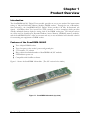
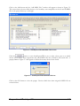
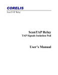
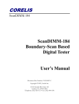
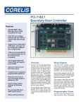
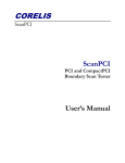
CORELIS
ScanDIMM-168/NC
ScanDIMM-168/NC
Boundary-Scan Based
Digital Tester
User’s Manual
CORELIS
ScanDIMM-168/NC
ScanDIMM-168/NC
Boundary-Scan Based
Digital Tester
User’s Manual
Document Part Number: 70355 Revision B
Copyright
2004, Corelis Inc.
Corelis, Inc.
12607 Hiddencreek Way
Cerritos, CA 90703-2146
Telephone: (562) 926-6727 • Fax: (562) 404-6196
Preface
PRINTING HISTORY
New editions are complete revisions of the manual. Update packages, which are issued between
editions, contain additional and replacement pages to be merged into the manual by the customer.
The dates on the title page change only when a new edition is published.
A software code may be printed before the date; this indicates the version of the software product at
the time the manual or update was issued. Many product updates and fixes do not require manual
changes and, conversely, manual corrections may be done without accompanying product changes.
Therefore, do not expect a one to one correspondence between product updates and manual
updates.
Revision A, March 2004
Revision B, January 2010
GENERAL NOTICE
Information contained in this document is subject to change without notice. CORELIS shall not be
liable for errors contained herein for incidental or consequential damages in connection with the
furnishing, performance, or use of material contained in this manual. This document contains
proprietary information, which is protected by copyright. All rights reserved. No part of this
document may be reproduced or translated to other languages without the prior written consent of
CORELIS.
CORELIS assumes no responsibility for the use of or reliability of its software on equipment that is
not furnished by CORELIS.
i
PRODUCT WARRANTY
This CORELIS product has a warranty against defects in material and workmanship for a period of
90 days from date of shipment. During the warranty period, CORELIS will, at its option, either
repair or replace products that prove to be defective.
For warranty service or repair, this product must be returned to a service facility designated by
CORELIS. Outside CORELIS service travel areas, warranty service will be performed at the
Buyer's facility only upon CORELIS' prior agreement and Buyer shall pay CORELIS' round trip
travel expenses.
For products returned to CORELIS for warranty service, the Buyer shall prepay shipping charges to
CORELIS and CORELIS shall pay shipping charges to return the product to the Buyer. However,
the Buyer shall pay all shipping charges, duties, and taxes for products returned to CORELIS from
another country.
CORELIS warrants that its software and firmware designated by CORELIS for use with an
instrument will execute its programming instructions when properly installed on that instrument.
CORELIS does not warrant that the operation of the instrument, software, or firmware will be
uninterrupted or error-free.
The foregoing warranty shall not apply to defects resulting from improper or inadequate
maintenance by the Buyer, Buyer-supplied software or interfacing, unauthorized modification or
misuse, operation outside of the environmental specifications for the product, or improper site
preparation or maintenance.
NO OTHER WARRANTY IS EXPRESSED OR IMPLIED. CORELIS SPECIFICALLY
DISCLAIMS THE IMPLIED WARRANTIES OF MERCHANTABILITY AND FITNESS FOR
A PARTICULAR PURPOSE.
EXCLUSIVE REMEDIES
THE REMEDIES CONTAINED HEREIN ARE THE CUSTOMER'S SOLE AND
EXCLUSIVE REMEDIES. CORELIS SHALL NOT BE LIABLE FOR ANY DIRECT,
INDIRECT, SPECIAL, INCIDENTAL, OR CONSEQUENTIAL DAMAGES, WHETHER
BASED ON CONTRACT, TORT, OR ANY OTHER LEGAL THEORY.
Product maintenance agreements and other customer assistance agreements are available for Corelis
products. For assistance, contact your nearest Corelis Sales and Service Office.
RETURN POLICY
No items returned to CORELIS for warranty, service, or any other reason shall be accepted unless
first authorized by CORELIS, either direct or through its authorized sales representatives. All
returned items must be shipped pre-paid and clearly display a Returned Merchandise Authorization
(RMA) number on the shipping carton. Freight collect items will NOT be accepted. Customers or
authorized sales representatives must first contact CORELIS with notice of request for return of
merchandise. RMA's can only originate from CORELIS. If authorization is granted, an RMA
number will be forwarded to the customer either directly or through its authorized sales
representative.
ii
Table of Contents
CHAPTER 1 PRODUCT OVERVIEW .......................................................................... 1-1
Introduction ............................................................................................................................................................... 1-1
Features of the ScanDIMM-168/NC.......................................................................................................................... 1-1
ScanDIMM-168/1.8V ................................................................................................................................................ 1-2
Daisy-Chaining the TAPs .......................................................................................................................................... 1-2
ScanDIMM-168/NC Specifications ........................................................................................................................... 1-3
CHAPTER 2 SCANDIMM-168/NC INSTALLATION .................................................... 2-1
What’s on the Disk .................................................................................................................................................... 2-1
Unit Under Test Board Layout .................................................................................................................................. 2-2
Daisy-Chaining Multiple ScanDIMM-168/NC Modules .......................................................................................... 2-2
Indicator LED ............................................................................................................................................................ 2-2
CHAPTER 3 PREPARATION OF TEST INPUT FILES ............................................... 3-1
Introduction ............................................................................................................................................................... 3-1
Testing the Socket Power and Ground Pins ............................................................................................................... 3-7
iii
List of Figures
Figure 1-1.
Figure 3-1.
Figure 3-2.
Figure 3-3.
Figure 3-4.
Figure 3-5.
Figure 3-6.
Figure 3-7.
iv
ScanDIMM-168 module (top view) ....................................................................................................... 1-1
ScanExpressTPG BSDL Files Phase ..................................................................................................... 3-2
ScanExpressTPG Add BSDL Files Screen............................................................................................. 3-3
ScanExpressTPG Added New Devices .................................................................................................. 3-3
ScanExpressTPG Add BSDL Files Screen After Auto-Find .................................................................. 3-4
ScanExpressTPG Populated BSDL Files Screen ................................................................................... 3-5
ScanExpressTPG Move Down Menu Selection ..................................................................................... 3-5
ScanExpressTPG BSDL File Phase with TAP Break ............................................................................ 3-6
List of Tables
Table 1-1. DC Characteristics .................................................................................................................................. 1-3
Table 2-1. TAP Connection List ............................................................................................................................... 2-2
v
Chapter 1
Product Overview
Introduction
The ScanDIMM-168/NC Digital Tester module provides an easy-to-use method for interconnect
testing of 168-pin Dual Inline Memory Module (DIMM) sockets. Through the use of BoundaryScan technology, the ScanDIMM-168/NC Digital Tester provides 158 fully bi-directional test
signals. A Boundary-Scan Test Access Port (TAP) connects to a host computer, which provides
virtually unlimited memory depth for testing each of the DIMM socket pins. The 168-pin sockets
are often used for Synchronous Dynamic Random Access Memory (SDRAM) memory modules,
and the ScanDIMM-168/NC offers an accurate and easy-to-use mechanical and electrical solution
for connecting test equipment to DIMM sockets.
Features of the ScanDIMM-168/NC
Tests 168-pin DIMM sockets
Tests for opens on the socket’s power and ground pins
3.3V interface, 5V tolerant
Daisy-chain an unlimited number of ScanDIMM-168/NC modules
LED indicates power-on
Compatible with ScanPlus software.
Figure 1-1 shows the ScanDIMM-168 module. (The NC version looks similar).
Figure 1-1. ScanDIMM-168 module (top view)
Product Overview
1-1
ScanDIMM-168/1.8V
The ScanDIMM-168/NC is designed to fit into the popular 168-pin, 3.3V-compatible DIMM
socket. A similar module, the ScanDIMM-168/NC/1.8V, fits into a 1.8V-compatible DIMM
socket. This manual applies to both the 3.3V and 1.8V modules but for the sake of simplicity it
references only the more popular 3.3V module. For ordering information on the 1.8V version,
please contact [email protected].
Daisy-Chaining the TAPs
Multiple ScanDIMM-168/NCs give access to units under test (UUTs) that contain multiple DIMM
sockets. Simply connect the TDO from one socket to the TDI on the next.
1-2
Product Overview
ScanDIMM-168/NC Specifications
Size and Form Factor
Compatibility
Dimensions
JEDEC MO-161
5.250 in. × 1.000 in. (JEDEC MO-161 AA
dimension)
0.050 inches
3.3V-compatible, 1.8V version also available
PCB thickness
Connector Keying
Number of Boundary-Scan Test Signals
158 per module
Maximum Test Clock (TCK) Frequency
Maximum TCK Frequency
25 MHz
PWR
Indicates 3.3V power source is present
LEDs
I/O and TAP Signals DC Characteristics
Parameter
Conditions
MIN
MAX
UNIT
Operating Power (VDD) – Provided via the 168 pin socket pins
3.00
3.60
V
High Level Input Voltage (VIH)
2.0
5.5
V
Low Level Input Voltage (VIL)
-0.30
0.80
V
Output High Level Voltage (VOH )
Output Low Level Voltage (VOL)
Input leakage Current (II)
IOH= -4 mA dc
2.90
V
IOH= -0.1 mA dc
3.10
V
IOL= 8 mA dc
0.40
V
IOL= 0.1 mA dc
0.20
V
10
A
VI = VDD or GND
Table 1-1. DC Characteristics
Product Overview
1-3
Power Requirements (Provided by the 168-pin mating socket)
3.30 V
0.200 A (Maximum)
Operating Environment
Temperature
Relative Humidity
0 C to 55 C
10% to 90%, non-condensing
Storage Environment
Temperature
1-4
-40 C to 85 C
Product Overview
Chapter 2
ScanDIMM-168/NC Installation
The ScanDIMM-168/NC product consists of the following components:
ScanDIMM-168/NC Module
User’s Manual
Configuration Disk
Ensure all materials listed are present and free from visible damage or defects before proceeding. If
anything appears to be missing or damaged, please contact Corelis at the number listed on the title
page.
What’s on the Disk
The disk contains the ScanDIMM-168/NC BSDL file:
Filename
Description
ScanDIMM-168NC.bsd
BSDL file for the ScanDIMM-168/NC Boundary-Scan
component.
ScanDIMM-168/NC Installation
2-1
Unit Under Test Board Layout
The Unit Under Test must be designed to support the ScanDIMM-168/NC module. The TAP
signals of the ScanDIMM-168/NC are connected to the edge connector that plugs into the socket
on the unit under test as shown in Table 2-1.
DIMM
Pin
Signal Name
I/O
44
TDI
In
48
TDO
Out
80
TMS
In
Test Mode Select
81
TCK
In
Test Clock
Description
Test Data In (to UUT)
Test Data Out (from UUT)
Table 2-1. TAP Connection List
The TDI to the socket should come from the TDO of a component in the scan chain or from the
connector. The TDO from the socket should go to the next component in the scan chain or to the
connector. The TMS and TCK from the Unit Under Test TAP must be connected to the socket as
well as any other boundary-scan components. Treat all TAP signals, especially TMS and TCK, as
critical nets. It is recommended that pull-up and pull-down resistors be placed at the end of the
TCK clock trace.
Daisy-Chaining Multiple ScanDIMM-168/NC Modules
To daisy-chain multiple ScanDIMM-168/NC modules, simply connect the TDO of one module to
the TDI of the next. TMS and TCK should be brought to all modules.
Indicator LED
The LED indicates the status of the ScanDIMM-168/NC module. D2 is labeled PWR. It
illuminates if the ScanDIMM-168/NC is receiving power from the target (through pins 41 and 84).
If the LED is not illuminated, the ScanDIMM-168/NC module is not powered up.
2-2
ScanDIMM-168/NC Installation
Chapter 3
Preparation of Test Input Files
Introduction
The ScanDIMM-168/NC integrates easily with a boundary-scan test plan. When the ScanDIMM168/NC is installed in a socket, the socket behaves like a boundary-scan component. Therefore, it
is not necessary to make any changes to the netlist to include the ScanDIMM-168/NC in a test plan.
Once the ScanDIMM-168/NC is plugged into the socket on the target board, the boundary-scan
test system will automatically test the socket. However, regeneration of the interconnect tests with
the included ScanDIMM-168/NC BSDL file is required (using ScanExpressTPG).
Copy the file ScanDIMM-168NC.bsd to your design directory.
Preparation of Test Input Files
3-1
Proceed through the ScanExpressTPG test generation steps normally until you get to the BSDL files
screen shown in Figure 3-1. This screen is used to detect the scan chain ordering and provide
information about the physical characteristics of the JTAG compatible devices on the board.
Figure 3-1. ScanExpressTPG BSDL Files Phase
3-2
Preparation of Test Input Files
Click on the Add button and the “Add BSDL Files” window will appear as shown in Figure 3-2.
This screen shows the most likely devices to be boundary scan compatible on the left and all BSDL
files in the project directory on the right.
Figure 3-2. ScanExpressTPG Add BSDL Files Screen
Click the
button to cause ScanExpressTPG to try to make a best guess as to which
devices are boundary scan components and which BSDL files they should be associated with. A
popup similar to Figure 3-3 will appear to indicate how many devices were found.
Figure 3-3. ScanExpressTPG Added New Devices
Click on the OK button to close the popup. Devices which have been assigned a BSDL file are
colored in blue.
Preparation of Test Input Files
3-3
Change the device filter option to All Devices to allow the ScanDIMM-168/NC device to be seen.
Figure 3-4 below shows an example target system with an Altera CPLD and a ScanDIMM-168/NC
module associated with their BSDL files.
Figure 3-4. ScanExpressTPG Add BSDL Files Screen After Auto-Find
Click on the Close button to return to the BSDL files screen.
3-4
Preparation of Test Input Files
The BSDL files screen now contains entries for all JTAG compatible devices on the board. An
example is shown in Figure 3-5.
Figure 3-5. ScanExpressTPG Populated BSDL Files Screen
The JTAG devices must appear on this screen in the actual order that they are in the scan chain on
the board. Select the ScanDIMM entry and right-click to bring up the menu. Select Move Down as
shown in Figure 3-6 to move the ScanDIMM entry down the list until it is at the bottom.
Figure 3-6. ScanExpressTPG Move Down Menu Selection
Preparation of Test Input Files
3-5
Click on the
button and ScanExpressTPG will attempt to put the devices into the
correct order. The status window shown will appear to show the processing status. The warnings
about the netlist not having a connection to the ScanDIMM may be safely ignored.
This window also displays any detected compliance enable information. Compliance enable
conditions must be met for the JTAG devices to function properly. When the processing
completes, click on the OK button to close the status window.
The BSDL files screen now contains entries for all JTAG compatible devices on the board in the
correct order with associated TAP Breaks. This can be seen in Figure 3-7.
Figure 3-7. ScanExpressTPG BSDL File Phase with TAP Break
Click the Next button to proceed with the rest of the test generation steps. ScanExpressTPG will
use the input files to generate the actual test patterns that will be applied to the board by ScanPlus
Runner.
3-6
Preparation of Test Input Files
Testing the Socket Power and Ground Pins
To test the power and ground pins on the ScanDIMM-168/NC socket, the constraint file should
have added syntax:
SENSE_HIGH VDD
SENSE_LOW GND
Where VDD and GND are the net names of the 3.3V SDRAM power and ground signals on the
target board. This syntax may already be present to test other power or ground connections in the
target system.
Preparation of Test Input Files
3-7