1
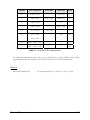
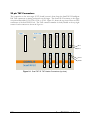
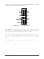
CORELIS ScanTAP-32 ScanTAP-32 Multiple TAP Intelligent Pod User’s Manual Document Part Number: 70332 REV C Copyright 2003-2007 Corelis Inc. 12607 Hiddencreek Way Cerritos, CA 90703-2146 Telephone: (562) 926-6727 • Fax.: (562) 404-6196 Preface PRINTING HISTORY New editions are complete revisions of the manual. Update packages, which are issued between editions, contain additional and replacement pages to be merged into the manual by the customer. The dates on the title page change only when a new edition is published. A software code may be printed before the date; this indicates the version of the software product at the time the manual or update was issued. Many product updates and fixes do not require manual changes and, conversely, manual corrections may be done without accompanying product changes. Therefore, do not expect a one to one correspondence between product updates and manual updates. Edition 1, March 2003 Edition 2, July 2006 Edition 3, September 2007 GENERAL NOTICE Information contained in this document is subject to change without notice. CORELIS shall not be liable for errors contained herein for incidental or consequential damages in connection with the furnishing, performance, or use of material contained in this manual. This document contains proprietary information, which is protected by copyright. All rights reserved. No part of this document may be reproduced or translated to other languages without the prior written consent of CORELIS. CORELIS assumes no responsibility for the use of or reliability of its software on equipment that is not furnished by CORELIS. i PRODUCT WARRANTY This CORELIS product has a warranty against defects in material and workmanship for a period of 90 days from date of shipment. During the warranty period, CORELIS will, at its option, either repair or replace products that prove to be defective. For warranty service or repair, this product must be returned to a service facility designated by CORELIS. Outside CORELIS service travel areas, warranty service will be performed at the Buyer's facility only upon CORELIS' prior agreement and Buyer shall pay CORELIS' round trip travel expenses. For products returned to CORELIS for warranty service, the Buyer shall prepay shipping charges to CORELIS and CORELIS shall pay shipping charges to return the product to the Buyer. However, the Buyer shall pay all shipping charges, duties, and taxes for products returned to CORELIS from another country. CORELIS warrants that its software and firmware designated by CORELIS for use with an instrument will execute its programming instructions when properly installed on that instrument. CORELIS does not warrant that the operation of the instrument, software, or firmware will be uninterrupted or error-free. The foregoing warranty shall not apply to defects resulting from improper or inadequate maintenance by the Buyer, Buyer-supplied software or interfacing, unauthorized modification or misuse, operation outside of the environmental specifications for the product, or improper site preparation or maintenance. NO OTHER WARRANTY IS EXPRESSED OR IMPLIED. CORELIS SPECIFICALLY DISCLAIMS THE IMPLIED WARRANTIES OF MERCHANTABILITY AND FITNESS FOR A PARTICULAR PURPOSE. EXCLUSIVE REMEDIES THE REMEDIES CONTAINED HEREIN ARE THE CUSTOMER'S SOLE AND EXCLUSIVE REMEDIES. CORELIS SHALL NOT BE LIABLE FOR ANY DIRECT, INDIRECT, SPECIAL, INCIDENTAL, OR CONSEQUENTIAL DAMAGES, WHETHER BASED ON CONTRACT, TORT, OR ANY OTHER LEGAL THEORY. Product maintenance agreements and other customer assistance agreements are available for Corelis products. For assistance, contact your nearest Corelis Sales and Service Office. RETURN POLICY No items returned to CORELIS for warranty, service, or any other reason shall be accepted unless first authorized by CORELIS, either direct or through its authorized sales representatives. All returned items must be shipped pre-paid and clearly display a Returned Merchandise Authorization (RMA) number on the shipping carton. Freight collect items will NOT be accepted. Customers or authorized sales representatives must first contact CORELIS with notice of request for return of merchandise. RMA's can only originate from CORELIS. If authorization is granted, an RMA number will be forwarded to the customer either directly or through its authorized sales representative. ii Table of Contents CHAPTER 1 PRODUCT OVERVIEW.......................................................1-1 Introduction ............................................................................................................................................................. 1-1 Features of the ScanTAP-32 ................................................................................................................................... 1-2 ScanTAP-32 Specifications ..................................................................................................................................... 1-2 CHAPTER 2 SCANTAP-32 INSTALLATION ...........................................2-1 ScanTAP-32 Installation ......................................................................................................................................... 2-1 System Power Up Sequence .................................................................................................................................... 2-1 20 pin TAP Connectors ........................................................................................................................................... 2-2 Connecting Multiple UUTs ..................................................................................................................................... 2-5 TAP Voltage Configuration .................................................................................................................................... 2-9 Connecting and Removing UUTs ......................................................................................................................... 2-11 iii Table of Figures Figure 1-1. Figure 2-1. Figure 2-2. Figure 2-3. Figure 2-4. Figure 2-5. iv ScanTAP-32........................................................................................................................................... 1-1 ScanTAP-32 TAP Header Connectors (top view).................................................................................. 2-2 20-Pin TAP Connector (top view) ......................................................................................................... 2-3 Target Configuration Window............................................................................................................... 2-8 Controller Configuration Window......................................................................................................... 2-9 Voltage Configuration Window ........................................................................................................... 2-10 Table of Tables Table 1-1. Table 2-1. Table 2-2. Table 2-3. Table 2-4. Table 2-5. Table 2-6. Table 2-7. Table 2-8. ScanTAP-32 DC Characteristics............................................................................................................. 1-3 20 Pin Connector Pinout......................................................................................................................... 2-4 TAP Utilization........................................................................................................................................ 2-5 TAP Connection for Targets With One TAP ........................................................................................... 2-6 TAP Connection for Targets With Two TAPs.......................................................................................... 2-7 TAP Connection for Targets With Four TAPs......................................................................................... 2-7 TAP Connection for Targets With Eight TAPs........................................................................................ 2-8 TAP Connection for Targets With Sixteen TAPs ..................................................................................... 2-8 ScanTAP-32 TAP Voltages Table.......................................................................................................... 2-10 v Chapter 1 Product Overview Introduction The ScanTAP-32 Multiple TAP Intelligent Pod is a desk-top/rack-mountable instrument that expands the Corelis high-speed boundary-scan interface to up to 32 TAPs. With the ScanTAP-32, a single PC equipped with the Corelis PCI-1149.1/Turbo controller card can simultaneously perform Boundary-Scan Testing and In System Programming (ISP) on up to 32 targets, each equipped with IEEE-1149.1 Test Access Ports (TAPs). The ScanTAP-32, shown in Figure 1-1, is configured to mount in a standard, laboratory 19-inch instrumentation rack. It can also be used on the desktop. Figure 1-1. ScanTAP-32 Product Overview 1-1 Features of the ScanTAP-32 The Corelis ScanTAP-32 Multiple TAP Intelligent pod connects to the PCI-1149.1/Turbo boundary-scan controller via the 68-pin SCSI II type HOST connector. Differential signal driving supports cables of up to 30 feet. Automatic delay mechanisms compensate for transport delays through the cable. The 32 TAPs are individually configurable for interface voltages from 1.25V to 3.30V. On-board voltage translation logic allows a host to chain these TAPs together, or to configure them for gang programming. During gang programming each TAP drives the same data out to up to 32 targets, and simultaneously programs and verifies them. Optional Slow Slew rate (Voltages limited to 1.8 V to 3.3 V for slow slew) is provided. ScanTAP-32 Specifications PCI-1149.1/Turbo Interface Host Connector 68-pin SCSI type (AMP part no. 787171-7 or equivalent) Host Cable Length: 6 foot (standard) - Corelis P/N 15339 15 foot (optional) - Corelis P/N 15328 30 foot (optional) - Corelis P/N 15329 TAP Interface TAP Connector 20-pin header, 3M part no. 3428-6302 or equivalent Mating TAP Connector 20-pin IDC (flat cable), 3M part no. 3421-6620 or equivalent Number of Concurrent TAPs 32 max Maximum TCK frequency 80 MHz Maximum scanning data length Unlimited Programmable Output Voltage 1.25V to 3.3V in 0.05V increments Independent Output Voltages Four (4) independent output voltages can be set: The first output voltage is for TAPs: 1, 5, 9, …, 29. The second output voltage is for TAPs: 2, 6, 10, …, 30. The third output voltage is for TAPs: 3, 7, 11, …, 31. The fourth output voltage is for TAPs: 4, 8, 12, …, 32. Programmable Input Voltage 0.50V to 2.0V in 0.05V increments Independent Input Voltages Four (4) independent input threshold voltages can be set: The first input voltage is for TAPs: 1, 5, 9, …, 29. The second input voltage is for TAPs: 2, 6, 10, …, 30. The third input voltage is for TAPs: 3, 7, 11, …, 31. The fourth input voltage is for TAPs: 4, 8, 12, …, 32. Signals DC characteristics See Table 1-1 1-2 Product Overview Symbol Test Conditions Limit Min Limit Max Units V IH Vdd >= 2.5V 2 Vdd + 0.5 V Vdd < 2.5V 0.65 × Vdd Vdd + 0.5 V Vdd >= 2.0V 0.7 V Vdd <= 2.0V 0.35 × Vdd V V IL V OH I OH = -2 mA V OL I OL = 2 mA Vdd – 0.35 V 0.45 V Vdd =1.65V I OH Vdd = 1.65V - 1.95V -4 mA I OL Vdd = 1.65V - 1.95V 4 mA Table 1-1. ScanTAP-32 DC Characteristics For additional information please refer to the Advanced Low Voltage CMOS (AVC) family signal characteristics data available from TI and from other AVC device manufacturers. Physical Box Outline Dimensions Product Overview 19” rack compatible (3U): 16.8 in. × 9..2 in. × 5.0 in. 1-3 Input Power Nominal Voltage 115 VAC at 60 Hz Input Range 90 to 264 VAC, 50 to 60 Hz Peak Inrush Current 50 Amp max at 115 VAC 80 Amp max at 230 VAC Input Line Current 5.0 Amp max at 115 VAC 2.5 Amp max at 230 VAC Operating Environment Temperature Relative Humidity 0C to 55C 10% to 90%, non condensing Storage Environment Temperature -40C to 85C Concurrent scanning at all TAPs occurs at up to the full TCK rate capability of the PCI1149.1/Turbo. 1-4 Product Overview Chapter 2 ScanTAP-32 Installation When you receive the ScanTAP-32 Multiple TAP Intelligent Pod product it should contain the following items: ScanTAP-32 Multiple TAP Intelligent Pod unit 6-foot Cable to connect the PCI-1149.1/Turbo Controller to the ScanTAP-32, Corelis P/N 15339 115 VAC power cord This ScanTAP-32 User’s Manual Ensure all materials listed are present and free from visible damage or defects before proceeding. If anything appears to be missing or damaged, contact Corelis at the number listed on the front cover immediately. ScanTAP-32 Installation Perform the following installation steps to connect the ScanTAP-32 intelligent pod to the PC System: 1. If you are installing the ScanTAP-32 in a 19” rack then make sure to connect the ground lug on the back panel of the ScanTAP-32 to the rack equipment ground according to local electric codes and safety practices. 2. Install the 115 VAC power cord into the ScanTAP-32 power connector on the back panel. 3. Connect one end of the 6-foot cable, Corelis P/N 15314, to the HOST connector on the ScanTAP-32 front panel. 4. Make sure that the HOST PC is turned OFF. Connect the other end of the host cable to the mating connector on the PCI-1149.1/Turbo controller (previously installed in a PCI slot of the host computer motherboard). 5. Make sure that all UUTs (targets) are powered down. 6. Connect one or more of each TAP connectors to a UUT, following the instructions in the PCI-1149.1/Turbo User Manual. System Power Up Sequence 1. Power up the ScanTAP-32 by plugging the other end of the power cord into a 115 VAC power outlet, avoiding contact with any of its electrodes. 2. Power-up the PC with the PCI-1149.1/Turbo. 3. Power-up each of the UUTs. ScanTAP-32 Installation 2-1 20 pin TAP Connectors The connection to the user target (UUT) board/system is done from the ScanTAP-32 Intelligent Pod TAP connectors to mating connectors on the target. The ScanTAP-32 connects to the target via optional flat cables, P/N 15310, 15311 or 15312. Figure 2-1 shows the top view of first ten TAP connectors of the ScanTAP-32 box. The TAP connector number is clearly labeled at the top right corner of each connector as shown in Figure 2-1. Pin 1 Pin 2 Pin 19 Pin 20 Figure 2-1. ScanTAP-32 TAP Header Connectors (top view) 2-2 ScanTAP-32 Installation There are 32 identical TAP connector on the front panel of the ScanTAP-32. Below is the top view of the target 20-pin connector header (0.100" x 0.100" spacing): Figure 2-2. 20-Pin TAP Connector (top view) The connector pinout is shown in Table 2-1. The first 5 signals on pins 1 through 9 are the standard IEEE-1149.1 signals. Corelis Flash Programming software supports two additional signals: the external write strobe signal (Write_Strobe*) and the external Ready/Busy* signal. The Write_Strobe* signal is active low and should be pulled up with a 1K resistor on the target board. It needs to be logically OR-ed with the flash Write-Enable (WE*) signal so that assertion of either the flash Write-Enable (WE*) signal or the external write strobe will assert the flash WE* input. The Ready/Busy* signal is an open-collector/open-drain signal which is directly tied to the same signal(s) on the Flash device(s). Pins 17 and 19 are not currently used and should not be connected. ScanTAP-32 Installation 2-3 Pin Signal Direction 1 TRST* Input to the UUT 2 GND 3 TDI 4 GND 5 TDO 6 GND 7 TMS 8 GND 9 TCK 10 GND 11 Write Strobe* (GPIO1) 12 GND 13 GPIO2 14 GND 15 Ready/Busy* (GPIO3) 16 GND 17 N.C. 18 GND 19 N.C. 20 GND Input to the UUT Output of the UUT Input to the UUT Input to the UUT Input to the UUT Discrete Input to UUT Output of the UUT Not connected (reserved) Not connected (reserved) Table 2-1. 20 Pin Connector Pinout The connector is a 3M part number 3428-6302. It is a 0.1" x 0.1" header with latch/ejector. Note that there are many other manufacturers who have similar parts. 2-4 ScanTAP-32 Installation Connecting Multiple UUTs The ScanTAP-32 TAPs are configurable to match the number of TAPs per target system. If a target system has more than one TAP then the ScanTAP-32 can be configured to chain multiple TAPs together (i.e. connect TDO of one TAP to TDI of the next TAP). Up to 16 TAPs can be chained together. Table 2-2 shows how the TAPs are utilized for multiple TAP targets. TAPs per Target Max Number ScanTAP-32 TAP Utilization of Targets 1 32 Full TAP utilization 2 16 Full TAP utilization 3 8 TAP4 of each 4 TAP group is unused 4 8 Full TAP utilization 5 4 TAP6-TAP8 of each 8 TAP group are unused 6 4 TAP7-TAP8 of each 8 TAP group are unused 7 4 TAP8, TAP16, TAP24 and TAP32 are unused 8 4 Full TAP utilization 9 2 TAP10-TAP16 of each 16 TAP group are unused 10 2 TAP11-TAP16 of each 16 TAP group are unused 11 2 TAP12-TAP16 of each 16 TAP group are unused 12 2 TAP13-TAP16 of each 16 TAP group are unused 13 2 TAP14-TAP16 of each 16 TAP group are unused 14 2 TAP15-TAP16 of each 16 TAP group are unused 15 2 TAP16 and TAP32 are unused 16 2 Full TAP utilization Table 2-2. TAP Utilization The following tables, Table 2-3 through Table 2-7, show the TAP connection for 1,2,4,8 and 16 TAP targets. ScanTAP-32 Installation 2-5 Single TAP Target ScanTAP-32 Target 1 TAP1 Target 2 TAP2 Target 3 TAP3 Target 4 TAP4 Target 5 TAP5 Target 6 TAP6 Target 7 TAP7 Target 8 TAP8 Target 9 TAP9 Target 10 TAP10 Target 11 TAP11 Target 12 TAP12 Target 13 TAP13 Target 14 TAP14 Target 15 TAP15 Target 16 TAP16 Target 17 TAP17 Target 18 TAP18 Target 19 TAP19 Target 20 TAP20 Target 21 TAP21 Target 22 TAP22 Target 23 TAP23 Target 24 TAP24 Target 25 TAP25 Target 26 TAP26 Target 27 TAP27 Target 28 TAP28 Target 29 TAP29 Target 30 TAP30 Target 31 TAP31 Target 32 TAP32 Table 2-3. TAP Connection for Targets With One TAP 2-6 ScanTAP-32 Installation Target (with 2 TAPs) ScanTAP-32 Target 1 TAP1, TAP2 Target 2 TAP3, TAP4 Target 3 TAP5, TAP6 Target 4 TAP7, TAP8 Target 5 TAP9, TAP10 Target 6 TAP11, TAP12 Target 7 TAP13, TAP14 Target 8 TAP15, TAP16 Target 9 TAP17, TAP18 Target 10 TAP19, TAP20 Target 11 TAP21, TAP22 Target 12 TAP23, TAP24 Target 13 TAP25, TAP26 Target 14 TAP27, TAP28 Target 15 TAP29, TAP30 Target 16 TAP31, TAP32 Table 2-4. TAP Connection for Targets With Two TAPs Target (with 4 TAPs) ScanTAP-32 Target 1 TAP1 - TAP4 Target 2 TAP5 - TAP8 Target 3 TAP9 - TAP12 Target 4 TAP13 - TAP16 Target 5 TAP17 - TAP20 Target 6 TAP21 - TAP24 Target 7 TAP25 - TAP28 Target 8 TAP29 - TAP32 Table 2-5. TAP Connection for Targets With Four TAPs ScanTAP-32 Installation 2-7 Target (with 8 TAPs) ScanTAP-32 Target 1 TAP1 - TAP8 Target 2 TAP9 - TAP16 Target 3 TAP17 - TAP24 Target 4 TAP25 - TAP32 Table 2-6. TAP Connection for Targets With Eight TAPs Target (with 16 TAPs) ScanTAP-32 Target 1 TAP1 - TAP16 Target 2 TAP17 - TAP32 Table 2-7. TAP Connection for Targets With Sixteen TAPs The ScanExpress Runner software will indicate how the TAPs are chained. Figure 2-3 below 16 targets with 2 TAPs each are being tested. Figure 2-3. Target Configuration Window 2-8 ScanTAP-32 Installation TAP Voltage Configuration The ScanTAP-32 implements a scaled architecture. One ScanTAP-32 module contains the logic of a ScanTAP-4 times eight (8). The TAP and I/O output voltage attribute is shared amongst each of the 8 blocks. There are four TAP output voltages, labeled TAP1, TAP2, TAP3, TAP4. These control TAP(4*N+1), TAP(4*N+2), TAP(4*N+3),TAP(4*N+4) for N=0,1,2,3,4,5,6,7. The TDO threshold voltage from the target may also be configured (although usually it is adequate to leave the setting as automatic. To set these voltages go to the ScanExpress Runner or ScanPlus Runner main window. Select Setup select Controller as shown in Figure 2-4 Figure 2-4. Controller Configuration Window Select Advanced. Figure 2-5 contains the output driver voltage and input threshold voltage. ScanTAP-32 Installation 2-9 Figure 2-5. Voltage Configuration Window Below is a table showing the voltages and threshold voltages set up in Figure 2-5. TAP Output Voltage Threshold Voltage TAP1, TAP5, TAP9, TAP13, TAP17, TAP21, TAP25, TAP29 3.3V 0.90V TAP2, TAP6, TAP10, TAP14, TAP18, TAP22, TAP26, TAP30 2.5V 0.90V TAP3, TAP7, TAP11, TAP15, TAP19, TAP23, TAP27, TAP31 1.8V 0.90V TAP4, TAP8, TAP12, TAP16, TAP20, TAP24, TAP28, TAP32 3.3V 0.90V Table 2-8. ScanTAP-32 TAP Voltages Table Note that the Output Voltage setting sets the output voltage for the following signals: TDI (output of the ScanTAP-32 TAPs) TMS TCK GPIO1 GPIO2 GPIO2 and the Input Threshold Voltage setting sets the input threshold voltage for the TDO signal (input of the ScanTAP-32 TAPs) 2-10 ScanTAP-32 Installation Connecting and Removing UUTs After the initial power up of the unit there is no further need to cycle power to the ScanTAP-32. To connect the TAP connector(s) to the target (UUT) perform these steps in the following order : Make sure that the target power is OFF. Make sure that the green ON LED on top of the ScanTAP-32 is illuminated. Install the TAP cable(s) on the ScanTAP-32 front panel SCAN TAP connectors.. Install the other side of the TAP cable(s) on the matching target TAP connectors. Now you can turn the target power ON. Disconnecting the UUTs from the ScanTAP-32 is done in reverse order. Appendix A in the PCI-1149.1/Turbo User’s Manual contains general recommendation for implementing compatible target TAP connector(s). Following these recommendations makes the connection to the target easy and straightforward. To accommodate target boards with TAP connectors other than this standard, Corelis offers short, custom adapter cables for connectors such as the Altera ByteBlaster connector, the Xilinx 9 pin header, the Lattice TAP connector or the TI 14 pin DSP connector) ScanTAP-32 Installation 2-11