1
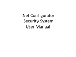
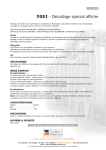
PUMP WATCH EXPRESS RTU ™ WEB-BASED CELLULAR REMOTE MONITORING CONTROL PANEL User Manual WATER SYSTEM INTEGRATOR AND CONTROLS PROVIDER WWW.PRIMEXCONTROLS.COM Ashland, OH 800-363-5842 Clearwater, FL 800-349-1905 Detroit Lakes, MN 888-342-5753 Milford, OH 513-831-9959 WARNINGS Failure to read and understand the information provided in this manual may result in personal injury or death, damage to the product or product failure. Please read each section in its entirety and be sure you understand the information provided in the section and related sections before attempting any of the procedures or operations given. Failure to follow these precautions could result in serious injury or death. Keep these instructions with warranty after installation. This product must be installed in accordance with National Electrical Code, ANSI/NFPA 70 so as to prevent moisture from entering or accumulating within the controller housing. ELECTRICAL SHOCK HAZARD A qualified service person must install and service this product according to applicable codes and electrical schematics. Disconnect power prior to servicing an equipment with the Pump Watch™ Express RTU. • Do not connect power to this equipment if it has been damaged or has any missing parts. • Do not install in areas with: excessive or conductive dust, corrosive or flammable gas, moisture or rain, excessive head, regular impact shocks, or excessive vibration. EXPLOSION OR FIRE HAZARD Do not use this product with flammable liquids. Do not install in hazardous locations as defined by National Electrical Code, ANSI/NFPA 70. PRIMEX® Pump Watch™ Express RTU User Manual TABLE OF CONTENTS Introduction & Ordering Information ........................................................... 1 Pump Watch™ Express RTU Introduction................................................... 2 Receiving and Inspection............................................................................ 2 Pump Watch™ Express RTU Features ....................................................... 3 Mounting the Pump Watch™ Express RTU................................................. 4 Wiring .......................................................................................................... 6 Sensor Wiring ............................................................................................. 7 Pump Watch™ Express Troubleshooting .................................................... 8 Activation and Service ................................................................................ 9 Pump Watch™ Express Setup Form ......................................................... 10 Logging In ................................................................................................. 11 Access Levels ........................................................................................... 12 Viewing/Searching for RTUs..................................................................... 13 Placing an RTU on the Map ..................................................................... 15 User Setup ................................................................................................ 16 Dashboard ................................................................................................ 17 RTU Setup ................................................................................................ 18 Online/Offline Trigger Alert Setup............................................................. 19 RTU Visualization ..................................................................................... 20 Main Screen Configuration ....................................................................... 22 RTU Parameter Configuration .................................................................. 23 Station Parameter Configuration .............................................................. 24 Alarm Notification Setup ........................................................................... 26 Reports & Trending................................................................................... 27 PRIMEX® Pump Watch™ Express RTU User Manual INTRODUCTION Designed for municipal wastewater lift stations and similar applications, the Pump Watch™ Express is a simple and effective RTU for management of a wastewater collection system via a cellular network. Alarms are monitored and service personnel notified in the event of a failure. Data logging and trending of critical information enables the User to visually track system performance and recognize impending problems. The station data can be visualized in a simple and intuitive way from your web browser on a PC, tablet or smart phone. ORDERING INFORMATION Two versions of the Pump Watch™ Express are available: • Pump Watch™ Express Light (Digital I/O only) • Pump Watch™ Express Premium (Analog & Digital I/O) The RTU module can be supplied for direct panel mounting, or pre-assembled in NEMA 4X enclosure for outdoor mounting near an existing panel. Note: All Pump Watch™ Express units include 1 year of cellular service. 1. Pump Watch™ Express RTU For installation inside a control panel. Parts Included: + or 771 7711 77 7 7 71 711 11 1 Pump Watch™ Express Lite 2. Pump Watch™ Express Premium + 3.7V Lithium Battery 100/150/200A Current Transducer (Premium version only) Options • High Gain Antenna (pole mounted) • Low Loss Cable - 20ft, 40ft and 60ft • 3dB Antenna with 6 foot cable • Mounting Bracket (3dB Antenna) for side mounting. • 24 Vdc Battery Backup (Analog & Digital) • Level Gage Transducer, 4-20mA, 0-15ft. WC, 50ft. cable • Level Rat Transducer, 4-20mA, 0-15ft. WC, 50ft. cable PRIMEX® 1 Pump Watch™ Express RTU User Manual PUMP WATCH™ EXPRESS RTU INTRODUCTION The Pump Watch™ Express remote monitoring system is designed to be connected to most simplex or duplex lift station type control panels. The Pump Watch™ Express RTU monitors pump run, run time, cycles, amps*, and flow. It can also monitor system in-flow*, power failure, level and level alarms*. All of this data is then relayed to the cloud, via a cellular network, to a secure website, and can be accessed and monitored from virtually anywhere in the world. * Amps, flow, and level measurements require Pump Watch™ Express Premium service. RECEIVING AND INSPECTION Pump Watch™ Express Lite Lite Unit ID Pump Watch™ Express Premium No analog terminals Premimum Unit ID Two analog inputs PUMP WATCH EXPRESS RTU ™ WEB-BASED CELLULAR REMOTE MONITORING CONTROL PANEL User Manual WATER SYSTEM INTEGRATOR AND CONTROLS PROVIDER WWW.PRIMEXCONTROLS.COM PRIMEX® Ashland, OH 800-363-5842 Clearwater, FL 800-349-1905 Detroit Lakes, MN 888-342-5753 Milford, OH 513-831-9959 (Premium version only) 2 Pump Watch™ Express RTU User Manual PUMP WATCH™ EXPRESS FEATURES PRIMEX® 3 Pump Watch™ Express RTU User Manual MOUNTING THE PUMP WATCH™ EXPRESS RTU 5.5”W x 4.5”H x 3.5”D (with antenna at 90 degrees as shown) Can be din rail mounted or panel mounted with 4 screws. PRIMEX® 4 Pump Watch™ Express RTU User Manual MOUNTING THE PUMP WATCH™ EXPRESS RTU Optional Outdoor Antenna and Mounting Bracket Backup Battery Connection PRIMEX® 5 Pump Watch™ Express RTU User Manual WIRING PUMP WATCH™ EXPRESS PREMIUM RTU SCHEMATIC BACKUP BATTERY CONNECTION TORQUE TO: 4.4-7.1 IN-LBS COM COM P1 P2 A2 A1 A3 A4 IN2 IN1 PUMP 1 RUNNING PUMP 2 RUNNING ALARM 1 ALARM 2 ALARM 3 ALARM 4 NC NO C REMOTE ACTIVATION CONTACTS (NON-POWERED) ATTENTION: CONNECT CONTACT CLOSURE INPUTS TO NON-POWERED CONTACTS ONLY 0V +24 24 VDC Supply Power LEVEL XDCR CURRENT XDCR PUMP WATCH™ EXPRESS LITE RTU SCHEMATIC BACKUP BATTERY CONNECTION TORQUE TO: 4.4-7.1 IN-LBS COM COM P1 P2 A1 A2 A3 PUMP 1 RUNNING PUMP 2 RUNNING ALARM 1 ALARM 2 ALARM 3 ALARM 4 A4 NC NO CONNECTION C NO 0V +24 24 VDC Supply REMOTE Power ACTIVATION CONTACTS (NON-POWERED) ATTENTION: CONNECT CONTACT CLOSURE INPUTS TO NON-POWERED CONTACTS ONLY PRIMEX® 6 Pump Watch™ Express RTU User Manual SENSOR WIRING CURRENT SENSOR EXAMPLE Connect the current transducer as shown on the schematics. Open the core of the current tranducer by pressing on the lever. Ensure that one (1) incoming power conductor passes through the center of the current transducer. *Premium version only PUMP RUN SIGNAL EXAMPLE Wire the pump run inputs to a non-powered auxiliary contact in the control panel, which closes when the pump is called to run. These must be wired for each pump. Motor contactor auxiliary contacts for reference only. Actual contactor configuration may differ. PRIMEX® 7 Pump Watch™ Express RTU User Manual PUMP WATCH™ EXPRESS TROUBLESHOOTING PROBLEM No reading from transducer. (level or current) (Premium version only) No flow reading is present. The Pump Watch™ Express web interface is not updating. CAUSE (S) Transducer wired incorrectly. Damaged or broken cable. Faulty transducer. The Pump Watch™ Express website has been configured incorrectly The Pump Watch™ Express panel is not powered on. SOLUTION (S) Check transducer connection. Repair the transducer cable. Replace the transducer. Check the Pump Watch™ Express website flow configuration. Ensure panel is powered. Move the Pump Watch™ Express panel to a less obstructed location or purchase a high gain, pole-mountable antenna to increase cellular strength. The cellular signal strength is too weak. The Pump Watch™ Express is not activated. Call the AMI™ customer support number. The Pump Watch™ Express website is experiencing problems. Indicating LED on the Pump Watch™ Express RTU Function LED (top of RTU) LD12 Green - External power (24Vdc). (Right) LD1 Green - Cellular Modem Power. LD2 Blue - Connecting to Cellular network (on power up). LD3 Red - App. LED #1. ON = Alarm/Fault present LD4 Yellow - Flash every 5 sec = RTU is ON LINE. Fast flash = OFFLINE I/O Status LED at the bottom of the RTU Each input has a corresponding LED indicator above the input terminal The relay output also has an LED indication. (See page 12 for details.) RTU COMMUNICATION The user can check the RTU signal strength (RSSI) on the web portal. RSSI THRESHOLDS RSSI is a measurement of the power present in a received radio signal (Received Signal Strength Indicator). The larger the number, the better the reception. Below is a guideline to appropriate strength thresholds: 1-5 = very poor (no communication 6-8 = poor (inconsistent communication) 9-11 = good (little to no communication issues) >12 = best SUPPORT For additional support, contact the AMI support team at: (888) 280-2060 PRIMEX® [email protected] 8 Pump Watch™ Express RTU User Manual ACTIVATION AND SERVICE The data management for Pump Watch™ remote cellular devices is hosted by: Aqua Management Incorporated, 6280 S. Valley View Blvd. Suite 212, Las Vegas, NV 89118 All Pump Watch™ Express RTUs are provided with a year of pre-paid cellular service. Activation of your device is required for operation. An account needs to be setup if this is your first Pump Watch™ device. Activate a new Pump Watch™ or Pump Watch™ Express device. User must fill in the Account Setup form and send it to a PRIMEX® contact person. Existing account? User must sent Activation request to a PRIMEX® contact person including the device ID + existing account name. YES NO (User already has an account and Pump Watch™ devices) Data needed: - Device ID number - Name and email of End User (will get the bill for service after the first year) - New Account name (Example: City of Fargo) - User login name request. PRIMEX® will forward request to AMI via: Support @aquamanagement.com Device typically activated within 2 hours (During office hours 9am-5pm Pacific time.) PRIMEX® will forward request to AMI via: Support @aquamanagement.com New Account will be created within 24 hours + device activated. End User Will receive login instructions via email. Will verify contact and billing information. Below is a list of PRIMEX® contact person for activation requests. PRIMEX® Location Contact Person / Phone Number Email Address Clearwater, FL Julian Atchia (800-746-6287 x 3462) [email protected] Clearwater, FL Russell Gardner (800-746-6287 x5110) Russell.Gardner@primex controls.com Ashland, OH Jason Mailloux (800-746-6287 x4110) [email protected] Plymouth, MN Troy Ladoux (763-559-0568 x 3915) [email protected] Detroit Lakes, MN Marty Grabarkewitz (800-746-6287 x 3357) [email protected] Pump Watch™ Express ID number (Located on the device) The Account Setup Form (on the next page) can be downloaded from: http://www.primexcontrols.com/municipal/remotemonitoring.html PRIMEX® 9 Pump Watch™ Express User Manual Pump Watch – Cellular RTU http://www.primexcontrols.com Pump Watch (Express) Account setup Form. (Sample) Fill in the User information First Name: Example: John Last Name: Example: Doe Example: [email protected] Email Address: Example: City of Fargo New Account Name: Example: Fargo123 Login Name: Example: 68023P Pump Watch Unit ID: FAQ Who should use this form? End Users who wish to create an account for monitoring Pump Watch units. End Users will be responsible for the service fee after the initial year is complete. Example of End Users: A City, Municipality, Water district, Utility Service Company, etc… Why create an account? Provides contact and billing information to AMI (Data Service Company). This will allow them to contact the End User directly with service renewal options after the first year is complete. A login and password will be setup to grant access to the Pump Watch (Express) web portal. Where to send this form? Compete this form sent to your PRIMEX contact person: Clearwater, FL Clearwater, FL Ashland, OH Plymouth, MN D. Lakes, MN Julian Atchia (800-746-6287 x3462) Russell Gardner (800-746-6287 x5110) Jason Mailloux (800-746-6287 x4110) Troy Ladoux (763-559-0568 x3915) Marty Grabarkewitz (800-746-6287 x3357) [email protected] [email protected] [email protected] [email protected] [email protected] When to create a new account? This form must be submitted at least 24 hours prior to the Pump Watch RTU activation. What happens next? Once the form is submitted, the End User will receive an e-mail (sent to the email address entered in this form) from AMI with a link and instructions for login and account verification. Click on the link or cut and paste it into our browser. Once the account is verified, the device is ready for use. For activation of future Pump Watch RTUs Once the account is setup, the End User can activate additional Pump Watch RTUs in the future, simply by sending an Email to your PRIMEX contact. (No forms are required) Include the Account Name and the Device ID of the Pump Watch RTU that needs to be activated. PRIMEX® 10 Pump Watch™ Express User Manual LOGGING IN Click on the following link or type in the following URL in your browser to open the login screen. http://www.primexlogin.com Google Chrome or Mozilla Firefox are the recommended web browsers. CUSTOMER SERVICE AGREEMENT AND TERMS OF USE This agreement outlines the agreement between AMI and the end User and must be agreed to before access to the cloud interface is allowed. An automatic email is generated and sent to the email address you entered. Follow the link in the email to verify and activate your account. After logging in again, you will need to agree to the Terms of Use. These steps only need to be completed during the initial setup and activation of your account. Notes: The end User should activate this product. When the initial 1 year of cellular service comes to an end, AMI will contact you directly and review renewal options. The primary User (Account Admin) will be able to add additional Users for login and alarm notification. The cellular service plan provided with the Pump Watch™ only covers text (SMS), and data for the Pump Watch™ Express unit. It does not cover SMS and Data service charges incurred for the use of your personal cell phone or tablet. PRIMEX® 11 Pump Watch™ Express User Manual ACCESS LEVELS The portal has three (3) levels of controls. • Dealer • Account Admin (Your Level) • User Run Reports X View Gateway Data X X Search Gateways X Name Gateways X X Configure Gateways2 X Place Gateways on Map1 Create Users X Assign Gateways to Accounts Create Account Admins Dealer Account Admin3 User Create Accounts Note! You may have multiple Account Admins and Users per account, but each Account Admin or User can only be assigned to one Account. X X X X X X X X X X X 1 With privileges assigned With privileges assigned 3 Accound Admin and User can work within assigned account only 2 PRIMEX® 12 Pump Watch™ Express RTU User Manual VIEWING/SEARCHING FOR YOUR DEVICE After you complete the registration procedure, you have access to your account and all of the RTUs contained within. There are multiple ways to search for/find/select a controller. • From Map (Satellite or road view available) • From List • From Tree View • Search by RTU Name or ID • Sort by RTU Name or ID FROM MAP When you log in, the interactive map appears on the main screen. If your RTU(s) have already been located on the map, it will appear here (the next section explains how to place the RTU on the map). Hover your mouse over a controller to see the device ID and other pertinent information. To select an RTU, click on the RTU icon. FROM LIST Clicking the button on the top of the page displays the available RTU by icon only. To select an RTU, click on the RTU icon. PRIMEX® 13 Pump Watch™ Express RTU User Manual FROM TREE VIEW On the left side of the window, all RTUs in the account are permanently displayed and can be clicked at any time to move from one RTU to another. To select an RTU from the Tree View, click on the RTU icon. SEARCH BY RTU ID OR NAME Clicking the at the top of the main page brings up an additional box where you can search for a RTU by the name or ID. or PRIMEX® 14 Pump Watch™ Express RTU User Manual SORT BY RTU ID OR NAME You may also sort your RTU by Name or ID by using the Sort by feature towards the top of the main page. Clicking on Name, places the RTUs in alphabetical order based on RTU name. Clicking on ID, places RTUs in numerical order based on the given ID of the unit (which cannot be changed). PLACING AN RTU ON THE MAP Account Adminstrators can place individual controllers on the map interface powered by Google Imagery. PLACING A CONTROLLER ON THE MAP • • Click at the top of the main screen. Click on to expand the Unlocated controllers (RTUs) in Summary box. • Click on the left magnifying glass as shown below to type in an address. You can zoom in manually on the map. • • • • Zoom In or Out until desired location is clearly in the viewing window Click on the controller you want to place. Move the cursor to map location and right click. Click Save Position. Note: Account Admins need special permissions to activate this feature. Contact AMI™ for assistance. PRIMEX® 15 Pump Watch™ Express RTU User Manual USER SETUP As an Account Admin, you can create/edit/delete Users, but not other Account Admins. To set up additional Account Admins, you need to contact the Dealer level admin or AMI support. NEW USER SETUP • Click at the top of the page. • Click and fill out the form. User Name (This will be the Login Name) First Name / Last Name / Primary Email Secondary Email - cell phone number to send alerts (Using Email to Text format - see below) Phone - optional Comments - optional Approve Date - select an approval date Access Level = USER Account = your account name Enable = check box • Click to save the information. An email will be sent to the Primary Email address with specific instructions on how to log in for the first time and how to setup a password. EMAIL TO TEXT AT&T - [email protected] Verizon - [email protected] T-Mobile - [email protected] Sprint PCS - [email protected] Virgin Mobile - [email protected] US Cellular - [email protected] Nextel - [email protected] Boost - [email protected] Alltel - [email protected] Example: If your phone number is 111-333-2222, and you are with Verizon, the email you should enter to receive a text for notification is: [email protected] EDIT EXISTING USER • • • • • Click at the top of the page. Click on the User you wish to change. Click . Edit the fields you wish to change. (Note: You can NOT change the Login Name.) Click to save the information and update the User. DELETE EXISTING USER • Click • Click on the User you wish to delete. • • Click . Confirm in the pop up box. PRIMEX® at the top of the page. 16 Pump Watch™ Express RTU User Manual DASHBOARD Ensure that the RTU has been properly configured. The functionality of this system is dependent on the setup of the RTU. Back RTUs available in your account User setup Edit RTU name RSSI RTU Name + ID Number Main Screen Configure RTU Get data from the RTU now* *The data on the screen may not contain the latest RTU values on opening. PRIMEX® 17 Pump Watch™ Express RTU User Manual RTU SETUP Click on the Setup button on the top row of the Main Screen to enter the RTU edit screen. Station ID# (cannot be edited) This number matches the one found on the Pump Watch™ Express RTU. Enter station designation Example: LS#24A (Lift Station 24A) GPS location for the station. You may enter coordinates or drag and drop on the map. Click PRIMEX® to store changes. It will take a few seconds to take effect. 18 Pump Watch™ Express RTU User Manual ONLINE/OFFLINE TRIGGER ALERT SETUP The Pump Watch™ Express has the ability to alert the user when the RTU transitions from online to offline and offline to online. Click on the tab on the setup screen to setup the online and offline triggers. Check the box and click on the button to enable and select the user for notification. See page 29 for more information on ALARM NOTIFICATION SETUP. The Online Triggered notification will alert the selected user when the RTU is connected to the cellular network and transmitting to the server. The Offline Triggered notification will alert the selected user if the RTU is no longer On-line (not connected to the server). This can be as a result of power loss for a prolonged time, or a drop in cellular service. It can take the server up to 20 minutes to detect this condition. PRIMEX® 19 Pump Watch™ RTU Express User Manual RTU VISUALIZATION Use the button to retrieve the latest values from the remote controller. Power Loss Alarm Alarm 1-4 Programmable alarms Pump High Amps Alarm1 Pump Dry Run Alarm (Low Amps)1 Station In-Flow1 Pump Runtime Alarm High Level Transducer1 Pump Amps (30 sec after start) Pump Run Indication Starts/day (last 24 hrs) Low Level Transducer1 Runtime in minutes (last 24 hrs) Fault Acknowledged Indicator Ack. Fault Button Pump Data Wet Well Level1 1 P1 & P2 GPM1 Relay Button (Relay will activate for 2 sec) Available on “Premium” versions on the Pump Watch™ Express only. ALARMS Light Version Alarm 1-4: These alarms become active upon a contact closure (see wiring schematics). The label “Alarm 1” can be changed to describe the actual alarm condition. Example: “P1 Fail”. (See pg. 24 for instruction on how to edit text on the Main Screen.) LED indication: The LED indication on the screen will turn red when the alarm is active. You can configure the alert notification by clicking on the indicator. Power: If 24 Vdc power is lost for more then the set time (see Configuration screen). The 3.7 Vdc battery must be connected. P1-2 Runtime Alarm: The pump ran continuously for longer than the set time (see Configuration screen). This condition may indicate a pump clog, a high in-flow event, or sensor fault. Premium Version Additional Alarms Xdcr High: Level transducer High Level alarm. This alarm set point and timer value is set in the configuration screen. The tank level value will go zero if 24 Vdc power is lost and the RTU keeps runing on the 3.7V Li ion battery. The High Level alarm will no longer be active druing this condition. It is recommended to have a 24 Vdc battery back up system to ensure alarm notification during power loss. Alternately, a high level float switch may be connected to any of the 4 digial alarms and activate during power loss. Xdcr Low: Level transducer Low Level alarm. This alarm set point and timer value is set in the configuration screen. This alarm will not be active on power loss (24 Vdc), and running on the 3.7V Li ion battery. P1-2 High Amps: The pump running amps are higher than set point for longer than the set timer (see Configuration screen). P1-2 Dry Run Alarm: The pump running amps are lower than set point for longer than the set timer (see Configuration screen). PRIMEX® 20 Pump Watch™ Express RTU User Manual RELAY BUTTON By pressing the on the screen, you will remotely energize the relay in the RTU. The relay will only stay ON for 2 seconds, then it will turn OFF automatically. The label text below the relay button can be edited to describe the function of the relay. Example: “Silence Horn”. See electrical schematics for relay wiring and rating information. CAUTION/DANGER Machine may start unexpectedly and cause serious injury or death. You must have confirmation that all personnel are free and clear from moving parts and the electrical panel before activating the relay remotely. Only allow qualified operators to remotely activate the relay. The relay remote operation must be part of a fail safe electrical circuit that would shutdown the equipment before failing or cause damage/injury. Local and National safety codes must be followed. ACK. FAULT BUTTON AND INDICATION The button must be pressed after an alarm within the set time (See Configuration screen). If an alarm becomes active, the timer starts and the operator must acknowledge the alarm on the screen before the timer times out (default value is 20 min). If not acknowledged the OK indicator turns red and can be used to notify other uses of the failure to acknowledge. This function is useful if only one user is on standby, and may not be able to respond in a timely manner. Click on to set the Alert notification. Leave it blank if you do not wish to use this function. STATION DATA (trending available - see Report & Trending section) Wet Well Level: Level of the wet well as measured by the transducer (See Configuration screen). P1-2 Amps: Pump Current captured 30 secs after start by the current transducer. P1-2 Cycles: The number of start cycles occurred during the previous 24hr period. P1-2 Runtime Minutes: The number of start cycles occurred during the previous 24hr period. A quick estimation of the station Gal/day = (P1 + P2) x GPM. A more accurate measurement of Gal/day can be derived from the In-Flow table format report. Station In-Flow (GPM): The measurements are calculated using the wet well level, the tank diameter and the fill time. It is very useful data point in tracking peak flow hours and to detect storm water infiltration issues. (See Configuration screen for parameter setup.) P1-2 GPM: The measurements are calculated using the wet well level, the tank diameter, the fill time and discharge time. It is a very useful data point in tracing the performance on each pump, and to understand the effect of changing head conditions. Pump Data: These values are not measured. They are used as reference and for record keeping. It is valuable to compare the pump FLA to the actual Amps on the screen for setting High Amp and Dry Run Alarms. It is also a quick way to check the pump data before making a service call to the station. PRIMEX® 21 Pump Watch™ Express RTU User Manual MAIN SCREEN CONFIGURATION MAIN SCREEN - Editing Text Labels On the Main Screen, double click on label text. and the screen will change to allow editing of the You can now edit the text labels with the red boxes. Example: To save changes press PRIMEX® , to cancel edits press 22 . Pump Watch™ Express RTU User Manual RTU PARAMETER CONFIGURATION Click on to navigate to the parameter Setup screen. PARAMETER PURPOSE DEFAULT VALUE Alarm 1-4 delay Delay timer used to confirm the presence of a closed contact. 2 Sec Power loss Alarm delay Delay timer used to confirm the loss of the 24Vdc power supply. 30 Sec High Tank Level Alarm delay Delay timer used to confirm the presence of a high level measurement from the transducer. This alarm is triggered by the High Tank Level value. 5 Sec Low Tank Level Alarm delay Delay timer used to confirm the presence of a low level measurement from the transducer. This alarm is triggered by the Low Tank Level value. 5 Sec If an alarm becomes active, the timer starts, and the operator must click the button on the screen before the timer times out. Acknowledge Alarm delay If not acknowledged, the indicator turns red and can be used to notify other users of the failure to acknowledge. This function is useful if only one user is on standby, and may not be able to respond in a timely manner. 20 Min Press PRIMEX® after edits to store values to the RTU. 23 Pump Watch™ Express RTU User Manual STATION PARAMETER CONFIGURATION LEVEL SENSOR SETUP (sold separately for Premium RTUs) PARAMETER DEFINITION DEFAULT VALUE Range (20mA) Level transducer measurement range. Value in Ft for 20mA output 15 Ft. Offset Level transducer distance above the bottom of the tank. This value is added to the measurement. 1 Ft. CURRENT SENSOR SETUP (supplied with Premium RTUs) PARAMETER DEFINITION DEFAULT VALUE Range (20mA) Current transducer measurement range. Value in A for 20mA output 100A ALARM SETUP PARAMETER DEFINITION DEFAULT VALUE High Tank Level High level set point for transducer high level alarm 12 Ft. Low Tank Level Low level set point for transducer low level alarm 0 Ft. P1-P2 Max Runtime Max timer value for pump runtime during a single cycle. The RTU is equipped with a maximum run time indicator. The unit can be configured to activate a message if a pre-determined maximum run time, per pump cycle, has been exceeded. This alarm requires the user to click on the to clear. 30 min. P1-P2 High Amp Max timer value for pump runtime during a single cycle. The RTU is equipped with a maximum run time indicator. The unit can be configured to activate a message if a pre-determined maximum run time, per pump cycle, has been exceeded. This alarm requires the user to click on the to clear. 80A P1-P2 Dry Run Dry Run indication uses the motor current measurement to determine whether a pump is running dry (no load). For a submersible pump, the current draw will typically drop 30% from normal when running dry. Please consult your pump manufacture for this value and test this fault, if possible. The amp set value corresponds to the minimum amp value that the pump should draw during normal operation. If the current drops below this value for longer than the Dry Run Delay, the remote telemetry unit will display a “Dry Run” fault. The “trip Delay” time is used to avoid nuisance tripping. This alarm requires the user to click on the button to clear. 0A Note: Setting values to “0” in the alarm setup will disable the alarm function. PRIMEX® 24 Pump Watch™ Express RTU User Manual FLOW MONITORING SETUP (PREMIUM) Volumetric flow measurement is available when a level transducer is used in a cylindrical tank. The Pump Watch™ Express unit calculates the volume of liquid based on the level. The flow is calculated by using the volume and the fill/discharge times. The in-flow and the discharge flow is measured. The Flow Calc. Level set points are not used for controlling the pump. They are used for volumetric flow calculation. The flow calculation is based on the diameter of the tank, the Start Flow Calc. and Stop Flow Calc. level set points, and the fill and discharge times. Both In-Flow and Discharge flow are calculated during every cycle. Tank Diameter: Enter the tank diameter in Ft. Flow Calc. Start Level: See below (in Ft.) Flow Calc. Stop Level: See below (in Ft.) Important notes on flow setup: Set Flow Calc. Start Level at least 4” below the pump start level. Set Flow Calc. Stop Level at least 4” above the pump stop level. The flow accuracy is better with longer cycle times (2 minutes or more). When using a rectangular tank, the equivalent diameter would be: d=2 LxW/ Example: A 10X10 tank would equate to a diameter of 11.28. Enter this value and get the flow calculations as if it was a cylindrical tank. L= length, W= width. PUMP DATA The Pump Data screen is for information only. It is a record on the pump HP, Volts, and FLA. Pump HP: Enter pump horsepower. Pump Voltage: Enter pump rated voltage. Pump FLA: Enter pump Full Load Amps (FLA) as shown on the nameplate. PRIMEX® 25 Pump Watch™ Express RTU User Manual ALARM NOTIFICATION SETUP EMAIL/TEXT ALARM NOTIFICATIONS Click on the alarm indicator to launch the “Led Alerts” dialog box. Click on “Select Users” to select which User will be notified when the alarm goes ON (condition set Alert), and when the alarm goes OFF (condition reset alert). Multiple Users may be selected for notification. To create additional Users, see “NEW USER SETUP” on page 19. Type in the Alert text message that will be delivered. You do not need to include the name of the station in the text as it is always sent as part of the notification. Wait a few seconds for the screen to update with the latest values from the cloud prior to making changes. Example of alarm notification Email: Subject: Alert Controller # [7156] LS # 42 (142 Street) From: [email protected] Date: Thu 01/23/2014 9:09 PM To: XXXXXXX #3 Power fail SMS (text) From: [email protected] Alert Controller # [7156] LS # 42 (142 Street) #3 Power fail PRIMEX® 26 Pump Watch™ Express RTU User Manual ACKNOWLEDGE FAULT FUNCTION The Acknowledge Fault function must be enabled at the RTU of Station View™ screen at the station. When enabled, a timer value must be entered (1min to 24h range). When disabled, the General fault alarm occurs immediately after any alarm. If any fault occurs, the indicator will turn red. The User must press the button before the timer set in the RTU times out. IF not pressed in time, the alarm will be activated. This alarm can be set to notify back up personnel, as alarms are active but not acknowledged in time. When the alarm is acknowledged, a notification message is sent via email and/or SMS (text). REPORTS & TRENDING Reports, data logging, and trending are available for visualization and downloading. These are very useful tools for evaluating the health of the pumps and for detecting sudden invents that may alter the normal operation of the station. Example: High inflow from water infiltration from a storm or other event. ACCESSING THE REPORT SCREEN Click PRIMEX® at the top of the page. 27 Pump Watch™ Express RTU User Manual To select which value to trend, select from the drop down menu: To select the time frame, click on Start Date. Click on to create the graph. To view a particular time frame, use the Zoom function. Simply click and drag on the graph. Use your mouse to view and follow the graph to view specific point value. Click on PRIMEX® to view export options. 28 Pump Watch™ Express RTU User Manual To view the data in tabular format, click on . To view Email notifications sent to Users, click on . All notifications sent are logged and can be viewed in a tabular format. The table can be exported to an Excel spreadsheet. (See sample below.) MessageTime DeliveredTime ToAddress 1/10/2014 8:57 1/10/2014 8:57 [email protected] Alert Controller # [7160] LS #10 St Pete Beach Subject #8 High level Float - Reset TextPart 1/10/2014 8:52 1/10/2014 8:50 [email protected] Alert Controller # [7160] LS #10 St Pete Beach #4 Power Fail - Reset 1/10/2014 8:50 1/10/2014 8:50 [email protected] Alert Controller # [7160] LS #10 St Pete Beach #8 High level Float 1/10/2014 8:36 1/10/2014 8:26 [email protected] Alert Controller # [7160] LS #10 St Pete Beach #1 Fault Acknowledged 1/10/2014 8:29 1/10/2014 8:29 [email protected] Alert Controller # [7160] LS #10 St Pete Beach #3 Power Fail When you are finished with your session, please logout of the system. Click PRIMEX® . 29 Pump Watch™ Express RTU User Manual WATER SYSTEM INTEGRATOR AND CONTROLS PROVIDER WWW.PRIMEXCONTROLS.COM Ashland, OH 800-363-5842 Clearwater, FL 800-349-1905 Detroit Lakes, MN 888-342-5753 Milford, OH 513-831-9959 PN 1045241A © 2015 SJE-Rhombus® Rev 09/15 PRIMEX is a trademark of SJE-Rhombus®