1
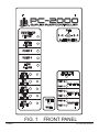
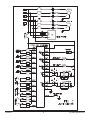
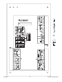
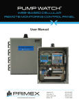
PC-2000
DUPLEX PUMP CONTROLLER
User Manual
WWW.PRIMEXCONTROLS.COM
Ashland, OH
800-363-5842
Clearwater, FL
800-349-1905
Detroit Lakes, MN
888-342-5753
Milford, OH
513-831-9959
PN 1038550A
© 2013 SJE-Rhombus® Rev 09/13
PRIMEX is a trademark of SJE-Rhombus®
PC2000
1.0 INTRODUCTION
The model PC-2000 is a float switch based dual pump controller intended primarily for
wastewater lift stations and other pump down applications. It has inputs for five normally
open float switches and sensor inputs for the seal fail and temperature fail sensors
normally found in submersible pumps. The controller has indicator lamps and test
push button switches on each of the float inputs as well as an indicator which illuminates
if the floats do not close in the correct order. The controller has built in alternation and
a three position switch to select automatic alternation or to select between pump 1
and pump 2 if alternation is off. The controller has disable inputs for each of the pumps.
The controller has built in support for an alarm horn with inputs for an external mute
button and also a mute button on the controller front panel. There are two alarm outputs.
One for the high alarm and one for the low alarm. These output relays can be
setup to cycle on and off during an alarm to support a blinking panel alarm light. The
controller has five output relays. Two are for the two pumps, one each for the high and
low level alarms, and one to drive the horn. The controller has indicator lights and external
relay drivers for the following conditions ( floats out of sequence, seal fail for pumps 1
and 2, temperature fail for pumps 1 and 2, pump disabled for pumps 1 and 2).
2.0 OPERATION
The PC-2000 uses five normally open float switches for level sensing. When the tank is
empty all of the floats are open. The lowest float is the low alarm float. If it is not used
the low float input should be shorted with a jumper. When the tank is empty the controller
will be in the low alarm condition. On rising water when the level is high enough
to close the low float switch then the low alarm will turn off. As the level rises the off
float will close and then the lead float will close. When this happens the pump controller
will call for the lead pump. Which pump is the lead, will be determined by the alternator.
If the alternator is set for pump 1 then pump 1 will be called. If the alternator is
set for pump 2 then it will be called. If the alternator is set in the on position then each
pump cycle the lead pump will change. If one of the pumps has and existing leak failure
then the other pump will be called as the lead. If any pump has existing temperature
failure or is disabled then that pump will not be called. If the lead pump lowers the water
level far enough to open both the lead and off floats then the lead pump will be turned
off and the lead pump changed if alternation is on. If the water level continues to rise
and closes the lag float then the lag pump will be called. If the level drops enough to
open the lag, lead, and off floats then the two pumps will be turned off. When both pumps
are turned off there is a 4 second delay between the first and second pump turning off.
If the water level continues to rise and closes the high alarm float then the high alarm
condition will be set. This will cause the high alarm relay and light to come on. This alarm
condition will clear when the level is low enough to open the high float. Any time a pump
is started an internal timer is started which will prevent the other pump from starting
for a period of time which is selected by one of the option switches on the bottom of
the controller. This time can be either 6 or 12 seconds.
The controller has three pairs of inputs for setting pump related alarms or faults.
PRIMEX™
2
PC-2000 Specifications
SEAL FAIL INPUTS
Each pump has an input for the seal fail ( moisture ) sensor commonly found in submersible
pumps. The controller measures the resistance of the sensor. In normal operation
the seal fail condition is set if the resistance is less than 50,000 ohms. One of the
option switches can be used to change this to set the alarm if the resistance is greater
than 50,000 ohms. If a seal fail alarm is set then that pump is demoted to lag pump and
its seal fail lamp and output are activated. The seal fail does not disable the pump.
TEMPERATURE FAIL INPUTS
Each pump has an input for the temperature fail sensor often found in pumps. This sensor
should be shorted if the pump is good. If the pump overheats then this sensor will
open. The sensor is connected to ground and to the sensor input for that pump. If the
pump controller detects an open condition in the sensor then the temperature fail lamp
and output are activated. The temperature fail condition will disable the pump. The controller
can be set using an option switch on the bottom of the controller to latch up
the temperature fail condition. If this option is selected then once a temperature fail
condition is detected the fault will not clear until the fault condition is cleared and the
reset push button is pushed (or external reset input is closed). If this option is not
selected then the fault will clear when the sensor in the pump closes again.
DISABLE / PUMP RUNNING INPUTS
Each pump has an input which has two possible functions. If the fail to start test is not
activated by an option switch on the bottom of the controller these inputs are pump
disables. Under this condition, if this input is shorted to ground then that pump will be
disabled. If the fail to start test is activated these inputs are pump running inputs and
should be shorted to ground when ever the pump is running.
FAIL TO START TEST
If the fail to start test is activated (using the option switches on the bottom of the
controller) then the following sequence is used each time a pump is called:
1. When a pump is called a timer is started.
2. After a start up time has expired (set by switch 6) the pump running input is
checked. If the pump is not running at the end of the time then a pump fail to start condition
is set and the pump is disabled. The pump will remain disabled until the reset button
is pushed, a high level alarm is set, or until the external reset input is activated.
ALARM RELAY OUTPUTS
The controller has two relays for level alarm. Option switch 5 can be used to cause
these relays to cycle on and off. This is useful to provide blinking on the external alarm
lights.
AUXILIARY RELAY
There is one relay which can have either of two functions selected by option switch 4.
PRIMEX™
3
PC-2000 Specifications
1. If the horn option is selected then this relay can be used to drive an external horn
or bell. Whenever either a high or low alarm condition starts the relay is activated
(closed). If the alarm condition is cleared then the relay is also cleared. If the reset button
is pushed or the external reset/mute input is activated then the horn relay is
cleared. If the horn is muted then it will not reactivate until the alarm condition is
cleared and another starts.
2. If the common alarm option is selected then this relay will be activated when any of
the following conditions exist:
• High alarm
• Low alarm
• Pump Temperature Failure
• Pump disabled by fail to start test
This common alarm condition can be used to drive an alarm light, telephone dialer, or
telemetry system.
OPTION SWITCHES
There are six switches on the back of the controller which select several different
options.
SW1 / When this switch is set the fail to start test is enabled
SW2 / When this switch is set the temperature fail condition is latched up until reset
SW3 / When this switch is set the seal fail input is inverted (open is fault)
SW4 / When this switch is set the aux relay is the common alarm. If it is not set then the aux relay is
the horn output.
SW5 / When this switch is set the low and high alarm relays will cycle to cause a lamp blink
SW6 / When this switch is set the time between pump starts and the delay for the fail to start test is
12 seconds instead of 6 seconds
FAULT OUTPUTS
There are seven fault lamps with corresponding driver outputs. They are use to display
the following fault conditions:
1. Floats out of sequence
2. Pump 1 seal fail
3. Pump 2 seal fail
4. Pump 1 temperature fail
5. Pump 2 temperature fail
6. Pump 1 disabled
7. Pump 2 disabled
Each of these has a corresponding relay drive output. These outputs are designed to
drive the coil of a 12VDC relay external to the controller. A source of 12VDC is also
provided. To use these outputs one side of the relay coil is connected to 12VDC and the
other coil connection is connected to the driver output.
3.0 SPECIFICATIONS
3.1 Float and Sensor Input
There are five float inputs, two seal fail sensor inputs, two temperature fail inputs, and
two disable inputs. They use current limiting resistors, filter capacitors and zener
diodes for transient protection. They also have both a hardware and a software filter
on these inputs to improve immunity from noise. They have the following specifications:
PRIMEX™
4
PC-2000 Specifications
Short Circuit Current
Open Circuit Voltage
-
less than 2 mA.
5.0 VDC
3.2 Mute / Reset Input
The mute / reset input is intended for use with a momentary push button switch mounted
on the dead front or on the side of the enclosure. It has the following specifications:
Short Circuit Current
Open Circuit Voltage
-
less than 2 mA.
5.0 VDC
3.3 Relay Outputs
There are five relays which are used for pumps and alarms. All of them except the low
alarm relay are form A (SPST) relays. The low alarm is a form C (SPDT) relay. They have
the following specifications:
Maximum current at 120 VAC
Maximum voltage
-
7 Amps with a resistive load
140 VAC
3.4 Power Inputs
The controller is designed to run on 120 VAC control power. It is internally fused at 1 Amp
and transient protected with a MOV transient protector. It uses transformer isolation and
internal current limited voltage regulators. It has the following specifications:
Input Voltage 120 VAC + or – 10% 50 to 70 Hz.
Maximum Current 0.4 amps
3.5 Operating and Storage Temperature Range
Operating Temperature
-
Storage Temperature
-
10 degrees C to 60 degrees C
0% to 95% relative humidity, non-condensing
20 degrees C to 65 degrees C
0% to 95% relative humidity, non-condensing
3.6 Fault Driver Outputs
The controller has seven open drain FET driver outputs for driving external relays, lights,
telephone dialers, or remote terminal units. The outputs short to ground when activated
and have the following specifications:
Maximum voltage +12VDC
Minimum voltage 0.0 VDC
Maximum continuous sink current +0.4 Amps
Maximum on resistance 2 ohms
Notes: Header and plugs use copper conductors only.
Torque requirement for plugs 1.47 Ft. Lbs.
Unit operates at “Pollution Degree 2”.
PRIMEX™
5
PC-2000 Specifications
4.0 CONNECTOR PIN DEFINITIONS
CONNECTOR J1
PIN FUNCTION
1
120 VAC HOT POWER INPUT TO THE CONTROLLER
2
120 VAC NEUTRAL POWER INPUT TO THE CONTROLLER
3
GROUND
4
GROUND
5
AUX RELAY CONTACT
6
AUX RELAY CONTACT
7
HIGH ALARM RELAY CONTACT
8
HIGH ALARM RELAY CONTACT
9
PUMP 2 RELAY CONTACT
10
PUMP 2 RELAY CONTACT
11
PUMP 1 RELAY CONTACT
12
PUMP 1 RELAY CONTACT
13
GROUND
14
LOW ALARM RELAY NORMALLY OPEN CONTACT
15
LOW ALARM RELAY COMMON CONTACT
16
LOW ALARM RELAY NORMALLY CLOSED CONTACT
CONNECTOR J2
PIN FUNCTION
1
PUMP 1 TEMPERATURE SENSOR INPUT
2
HIGH FLOAT INPUT
3
LAG FLOAT INPUT
4
LEAD FLOAT INPUT
5
OFF FLOAT INPUT
6
LOW FLOAT INPUT
7
PUMP 1 DISABLE / RUNNING INPUT
8
PUMP 2 DISABLE / RUNNING INPUT
9
PUMP 1 SEAL FAIL SENSOR INPUT
10
PUMP 2 SEAL FAIL SENSOR INPUT
11
PUMP 2 TEMPERATURE SENSOR INPUT
12
MUTE / RESET INPUT
CONNECTOR J3
PIN FUNCTION
1
+12 VDC VOLTAGE FOR EXTERNAL RELAYS
2
PUMP 1 DISABLE OUTPUT
3
PUMP 2 DISABLE OUTPUT
4
PUMP 1 TEMPERATURE FAIL OUTPUT
5
PUMP 2 TEMPERATURE FAIL OUTPUT
6
PUMP 1 SEAL FAIL OUTPUT
7
GROUND
8
PUMP 2 SEAL FAIL OUTPUT
9
FLOATS OUT OF SEQUENCE OUTPUT
10
RS232 RECEIVE
11
RS232 TRANSMIT
12
AUXILIARY INPUT
PRIMEX™
6
PC-2000 Specifications
PC-2000
DUPLEX PUMP CONTROLLER
ALT
AUX RELAY
/ HORN
1-2
2-1
ALTERNATION
HIGH
ALARM
PUMP 2
PUMP 1
LOW
ALARM
FLOATS OUT
OF SEQUENCE
HIGH
FLOAT
LAG
FLOAT
PUMP 2
SEAL FAIL
PUMP 1
LEAD
FLOAT
PUMP 2
TEMP FAIL
OFF
FLOAT
LOW
FLOAT
PUMP 1
RESET
DISABLED
MUTE
FIG. 1
PRIMEX™
PUMP 2
PUMP 1
FRONT PANEL
7
PC-2000 Specifications
PRIMEX™
8
PC-2000 Specifications
PRIMEX™
9
PC-2000 Specifications
PC-2000
DUPLEX PUMP CONTROLLE
PRIMEX™
10
PC-2000 Specifications