1
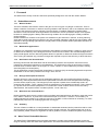
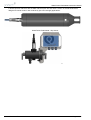
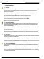
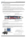
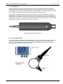
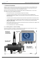
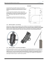
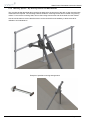
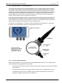
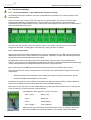
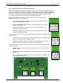
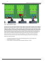
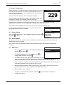
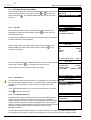
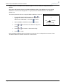
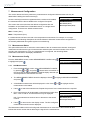
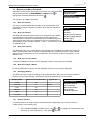
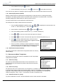
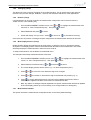
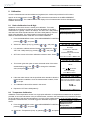
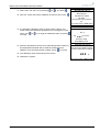
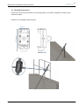
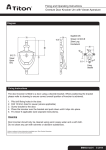
INSTRUCTION MANUAL
WaterTechw² Redox8000 Sensor
** This page is intentionally left blank **
WaterTechw² Redox8000 Instruction Manual
Table of Contents
1 Foreword....................................................................................................................................................... 5
1.1 Redox Measurement............................................................................................................................ 5
1.1.1 What is Redox?............................................................................................................................ 5
1.1.2 Wastewater Applications.............................................................................................................. 5
1.1.3 Nitrification and De-nitrification..................................................................................................... 5
1.1.4 Biological Phosphorus Removal................................................................................................... 5
1.1.5 What does the mV Scale Mean?.................................................................................................. 5
1.1.6 Summary...................................................................................................................................... 5
1.2 WaterTechw² Redox8000 Sensors....................................................................................................... 5
2 Introduction................................................................................................................................................... 7
2.1
2.2
2.3
2.4
Manual Conventions............................................................................................................................. 7
WaterWatch² Trademark....................................................................................................................... 7
Scope of Manual................................................................................................................................... 7
External Sensors.................................................................................................................................. 7
3 Safety Precautions........................................................................................................................................ 8
3.1
3.2
3.3
3.4
3.5
General ................................................................................................................................................ 8
Electrical installation............................................................................................................................. 8
Operating.............................................................................................................................................. 8
Service and Maintenance..................................................................................................................... 8
End of Life Disposal.............................................................................................................................. 9
4 The Sensor and Installation....................................................................................................................... 10
4.1
4.2
4.3
4.4
The WaterTechw² Sensors................................................................................................................. 10
Flowcell Assembly.............................................................................................................................. 10
Dip Housing........................................................................................................................................ 11
Insertion Electrode.............................................................................................................................. 11
5 Mechanical Installation................................................................................................................................ 12
5.1.1 Mounting Options – Flowcell assembly.......................................................................................12
5.1.2 Mounting Options – Dip Housing................................................................................................ 13
5.1.3 Mounting Options – Dip Housing Shaft Mount............................................................................13
5.1.4 Mounting Options – Dip Housing Handrail and Wall Brackets....................................................14
5.1.5 Mounting Options – Insertion Electrode......................................................................................15
5.1.6 Customer Supplied Brackets...................................................................................................... 15
5.2 Electrical Installation........................................................................................................................... 16
5.2.1 Electrical Installation – Dip or ModTechw² Interface to 7300w²..................................................16
5.2.2 Sensor Connections................................................................................................................... 16
5.2.3 ModTechw² Interface connections to Sensors............................................................................17
5.2.4 Extending Sensor Cables........................................................................................................... 18
6 Sensor Configuration.................................................................................................................................. 19
6.1
6.2
6.3
6.4
Sensor Config..................................................................................................................................... 19
Sensor Status..................................................................................................................................... 19
Add Sensor......................................................................................................................................... 19
S:0x WaterTechw² Redox8000........................................................................................................... 20
6.4.1 S:0x Info ..................................................................................................................................... 20
6.4.2 S:0x Remove.............................................................................................................................. 20
6.4.3 S:0x Modbus Address................................................................................................................. 20
226686IM-01 Issue Date 19/09/2013
Page 3 of 34
WaterTechw² Redox8000 Instruction Manual
7 Measurement Configuration........................................................................................................................ 22
7.1 Measurement Status........................................................................................................................... 22
7.2 Measurement Config........................................................................................................................... 22
7.2.1 Add Measurement...................................................................................................................... 22
7.3 Measurement Menu Redox8000......................................................................................................... 23
7.3.1 M:0x Info (Redox)....................................................................................................................... 23
7.3.2 M:0x Title (Redox)...................................................................................................................... 23
7.3.3 M:0x Units (Redox)..................................................................................................................... 23
7.3.4 M:0x Set Cal Low (124mV)......................................................................................................... 23
7.3.5 M:0x Set Cal High (300mV)........................................................................................................ 23
7.3.6 Averaging (Redox)...................................................................................................................... 23
7.3.7 Remove (Redox)......................................................................................................................... 23
7.3.8 M:0x Display Position (Redox).................................................................................................... 24
7.3.9 M:0x Restore Defaults (Redox)................................................................................................... 24
7.4 Measurement Menu Temperature...................................................................................................... 24
7.4.1 M:0x Info (Temp)........................................................................................................................ 24
7.4.2 M:0x Title (Temp)........................................................................................................................ 24
7.4.3 M:0x Set Cal (25.0°C) (Temp).................................................................................................... 24
7.4.4 Averaging (Temp)...................................................................................................................... 25
7.4.5 Remove (Temp).......................................................................................................................... 25
7.4.6 M:0x Display Position (Temp)..................................................................................................... 25
7.4.7 M:0x Restore Defaults................................................................................................................ 25
8 Calibration .................................................................................................................................................. 26
8.1 Redox Calibration Low & High............................................................................................................ 26
8.2 Temperature Calibration..................................................................................................................... 26
9 Maintenance............................................................................................................................................... 28
9.1 General cleaning ................................................................................................................................ 28
9.2 Inspection........................................................................................................................................... 28
10 Optional Accessories................................................................................................................................ 29
11 Technical Support..................................................................................................................................... 30
11.1 Returning Equipment for Repair....................................................................................................... 30
12 Technical Specification ............................................................................................................................ 31
12.1
12.2
12.3
12.4
12.5
12.6
12.7
Page 4 of 34
Physical Flowcell.............................................................................................................................. 31
Physical Dip (excluding shaft)........................................................................................................... 31
Environmental Data.......................................................................................................................... 31
Electrical .......................................................................................................................................... 31
Service Replacement........................................................................................................................ 31
Measurement.................................................................................................................................... 31
Mounting Options (Dip)..................................................................................................................... 31
226686IM-Iss01 Issue Date 19/09/2013
WaterTechw² Redox8000 Instruction Manual
1 Foreword
The WaterTechw² family of sensors has been specifically designed for use with the 7300w² Monitor.
1.1
Redox Measurement
1.1.1
What is Redox?
The terms oxidation and reduction refers to the gain or loss of oxygen or hydrogen or electrons. There is
always a transfer of electrons in reactions involving oxidation and reduction, that is, the oxidation state of one
or more of the elements is always changed. The term Redox or Oxidation-Reduction Potential (ORP)
describes a chemical reaction involving oxidation and reduction, the two processes always occur together
because an oxidising agent is always reduced during oxidation and a reducing agent is always oxidised
during reduction.
Redox Potential is a measure of the power of a substance to gain electrons in solution. A strong reducing
agent which readily loses electrons (which it can give to another substance), will have a high negative redox
potential. A strong oxidising agent will have a high positive redox potential. (Redox potential is the same as
electrode potential)
1.1.2
Wastewater Applications
As Redox is a measurement of levels of reduction and oxidation processes within a solution or liquor it's use
to determine the efficiency of the biological removal of ammonia and nitrate in the Activated Sludge Plants
(ASP) would appear obvious. Monitoring Redox allows an operator to determine whether biological reactions
are occurring and whether any processes changes are required to improve the efficiency of those reactions.
1.1.3
Nitrification and De-nitrification
Discharge limits mean that nitrification and de-nitrification processes are required to remove ammonia,
nitrate and to break down pollutants in the wastewater. The nitrification process is performed by nitrifying
bacteria when he Redox value is in the region of +100 to +350mV. In this condition the process is turning
ammonia (NH3) into nitrate (NO3-).
The de-nitrification process reduces the nitrate (NO3-) to nitrogen (N2), the de-nitrifying bacteria require the
wastewater to have a redox potential in the range -50 to +50 mV.
1.1.4
Biological Phosphorus Removal
Nutrient removal is a key process area in wastewater treatment, with ever lowering discharge consents.
Whilst many chemical processes have been implemented to aid the removal of Phosphorus the biological
process still has a part to play. The biological process requires a phase where volatile fatty acids in an
anaerobic tank (Redox: -100 to -225mV) cause the phosphorus to be released into solution. This is followed
by a phase where this soluble phosphorus is converted into a solid condition which can be removed by
sedimentation, this requires aerobic conditions (Redox: +25 to +250 mV).
1.1.5
What does the mV Scale Mean?
Redox electrodes and hence the monitors and controllers associated with them provide an output that varies
from -2000 to +2000 mV, in practice the measurement span is more like +/- 500 mV. An increasing -ve
reading indicates the presence of a reducing agent such as BOD or COD, whereas an increasing +ve value
indicates the presence of an oxidising agent such as Oxygen.
1.1.6
Summary
The use of Redox or ORP as a control parameter in wastewater treatment has the potential to reduce costs
and to enhance the quality of the treated water and the sludge produced. This measurement has yet to be
fully exploited, please contact our engineers for further guidance on how to install and operate our products.
1.2
WaterTechw² Redox8000 Sensors
The WaterTechw² Redox8000 sensor has been designed to provide highly reliable operation across the
range of drinking water and waste water applications. The flat faced electrode included the latest innovations
Page 5 of 34
226686IM-Iss01 Issue Date 19/09/2013
WaterTechw² Redox8000 Instruction Manual
in double junction reference with the ERP reference path. We also offer a version of the electrode that is
designed to monitor redox in low conductivity (low ionic strength) applications.
WaterTechw² Redox8000 – Dip Sensor
WaterTechw² Redox8000 – Flow Cell with Electrode
226686IM-01 Issue Date 19/09/2013
Page 6 of 34
WaterTechw² Redox8000 Instruction Manual
2 Introduction
2.1
Manual Conventions
All dimensions stated in this manual are in millimetres unless otherwise stated.
The manual has been written assuming the user has a basic knowledge of instrumentation and an
understanding of the type of measurement being made. Training in the use of the 7300w² Monitor and
sensors can be provided, please contact Partech for further information.
Icons have been used throughout this manual to draw your attention to precautions and useful notes.
They are categorised in the following way-
NOTES: General notes of interest to the user.
GENERAL CAUTION: Used where caution is required to prevent injury, damage, corruption of
data, loss of calibration or invalidation of warranty etc.
INSTALLATION NOTES: General installation notes of interest to the installer.
ELECTRICAL CAUTION: Used where there is a danger of electric shock to the installer or end
user, or where caution is required to prevent damage to the instrument.
MAINTENANCE NOTES: Used to highlight recommended maintenance procedures and help with
fault finding.
ENVIRONMENTAL NOTES: General notes on environmental issues, waste and disposal.
2.2
WaterWatch² Trademark
WaterWatchw² is the family name for the w² range of monitors and sensors. Sensors and instruments
designed for specific use with the 7300w² Monitor will be suffixed with the w² trademark.
2.3
Scope of Manual
This manual describes the installation, configuration, testing and operation of the WaterTechw² Redox8000
sensor. Please refer to 7300w² Monitor manual for standard functions of the 7300w² Monitor.
2.4
External Sensors
External sensors refers to any sensors, expansion modules or instruments connected externally to the
7300w² Monitor.
Page 7 of 34
226686IM-Iss01 Issue Date 19/09/2013
WaterTechw² Redox8000 Instruction Manual
3 Safety Precautions
3.1
General
Read the safety precautions carefully.
Check the delivery of your WaterTechw² Sensor for damage. Any damage should be reported to your
supplier as soon as possible.
Use care when unpacking the sensor. NEVER use sharp instruments to open the packaging, as this can
cause damage to the sensor or cable.
Only use accessories specifically manufactured by Partech for use with this sensor.
Read the operating instructions carefully before installing and operating this sensor.
Keep the cable connections dry and free from contamination during installation.
Keep the sensor away from high voltage cables.
3.2
Electrical installation
Only suitably qualified personnel or competent person may install, operate or repair this equipment. The
installer must ensure all electrical installation comply with local wiring regulations and standards (refer to
BS7671 for UK installations).
Please check the sensor has been terminated correctly. Incorrect termination may causes damage to the
sensor or monitor.
The WaterWatch² family of sensors are designed exclusively for use with the 7300w² Monitor. DO NOT
connect to other monitors.
Sensors need to be correctly addressed to the monitor before use. Please read the Sensor Configuration
section of this manual for full details.
3.3
Operating
Because these sensors have a wide range of applications, users must acquire the appropriate knowledge to
use these sensors in their specific application.
Partech are always available to provide advice and assistance in your application. Please contact Partech for
further information.
These sensors must be correctly calibrated before use. Please read the Calibration section of this manual for
full details of calibration procedures.
3.4
Service and Maintenance
Before maintenance, this equipment must be isolated or disconnected from HAZARDOUS LIVE voltages
before access.
Maintenance instructions for the WaterTechw² pH8000/Redox8000 sensors should be carried out as
specified in this instruction manual. Failure to carry out regular maintenance could invalidate the Warranty.
Services and repairs must be carried out by a Partech engineer. Partech can provide a service contract for
your system. Please ask for details.
226686IM-01 Issue Date 19/09/2013
Page 8 of 34
WaterTechw² Redox8000 Instruction Manual
3.5
End of Life Disposal
Equipment should be recycled according to local regulations.
Any calibration solutions should be disposed of as described in the Manufacture Safety Data Sheet
accompanied with the calibration solution.
Partech can provide recycling and disposal of your old Partech equipment, and may also provide the same
service for other manufactures equipment when replaced with Partech equipment.
Partech may provide a trade-in for old Partech equipment when upgrading your system. Please contact us
for further information.
Page 9 of 34
226686IM-Iss01 Issue Date 19/09/2013
WaterTechw² Redox8000 Instruction Manual
4
The Sensor and Installation
Whilst every attempt has been made to ensure that these instructions are correct, common sense and good
engineering practice should always be used, as every installation can present a new set of challenges and
difficulties. If you are in any doubt please contact Partech or your local distributor for further information.
4.1
The WaterTechw² Sensors
1. The Redox8000 sensor consists of an electronic assembly and a “consumable” replaceable part.
The WaterTechw² Redox8000 sensor has been designed to provide highly reliable redox measurement
along with temperature. The sensor uses a flat surfaced electrode which includes an extended reference
path, these features combine to provide an extremely robust redox measurement, suitable for use in surface
water, waste water and drinking water applications.
The electrode uses field proven flat surface, self-cleaning technology. The reference system is
enhanced by the Extended Path Reference (ERP) design which provides a complex path to protect the
reference in the presence of interacting ions such as proteins, silver and sulphides.
Electrode body – PPS or Ryton
3.5M Acrylamide Gel
Large Volume resists contamination
ERP = Extended Reference Path
Contaminants needs to travel further
UHWW HDPE pH Junction
The above illustration shows the internal construction of the pH8000 electrode.
4.2
Flowcell Assembly
Our flowcell assemblies are intended for applications where it is not possible to gain direct access to
the sample using a dip sensor, these are typically applications in drinking water and final effluent
discharge.
The WaterWatchw² platform has been designed to accommodate multiple sensors and multiple
parameters in the same 7300w² Monitor. Versions of this flowcell are available to combine pH
measurement with Turbidity, Redox and DO. These combinations provide an extremely cost effective
way of monitoring for regulatory or control purposes.
Flowcell Assembly
Multiple Sensor Flowcell Example
226686IM-01 Issue Date 19/09/2013
Page 10 of 34
WaterTechw² Redox8000 Instruction Manual
4.3
Dip Housing
The Dip housing has been specifically designed for use in open channels and easy access points.
Mounting shafts are available in a variety of lengths to suit any application. They range from 0.5 to 3.0
metre lengths. A range of mounting bracket options are also available. See Mounting Options section
of this manual for full details. The sensor connects directly to the 7300w² Monitor.
For installation in applications where gross fouling is anticipated we recommend that the sensor is
installed using our specially designed mounting system, with a flexible joint in the mounting shaft. The
flexible joint moves the sensor in the process, reducing bio-fouling and allowing rags to fall away from
the assembly. This motion is similar to that achieved by using a floating ball assembly, with the added
advantage of placing the sensor below the surface of the liquid.
WaterTechw² Redox8000 Dip Sensor
4.4
Insertion Electrode
The Insertion Electrode has been specifically designed for use in closed loop pipe systems. Mounting
boss must be fixed to the pipework to allow the sensors to be fitted. Partech can provided these
specific for your application. The sensors are provided with a ModTechw² interface box that allows
easy termination of the sensor cable to the monitor.
Page 11 of 34
226686IM-Iss01 Issue Date 19/09/2013
WaterTechw² Redox8000 Instruction Manual
5 Mechanical Installation
Reliable accurate measurement from any instrument can only be achieved by correct installation of the
measuring device; in the case of the WaterTechw² Redox8000 Sensor, this is particularly important. If
you are in any doubt contact Partech or your local distributor for advice.
Below are some points that should be considered before starting to install the sensor, or in the event
an installed sensor gives unreliable measurements•
Ensure that the sensor is immersed deeply enough into the sample.
•
The sensor should be mounted in such a way as to allow easy access for calibration and
maintenance. It should be possible to remove the sensor from the process without the need to shut
the process down.
•
The sensor must be monitoring a sample of the process that is representative of the whole process.
•
To allow a single technician to calibrate and maintain the system the sensor should be placed within
sight of the 7300w² Monitor. Although cable runs of up to 100 metres are possible operational
problems can be caused.
•
When possible, angle the sensor so that it is pointing down stream, this will allow any “ragging” to be
removed by the flow past the sensor.
•
Do not install where there is a likelihood of freezing.
5.1.1
Mounting Options – Flowcell assembly
The flowcell assembly is mounted on a single stainless steel plate with 4x 6.5mm fixing holes. Allow a
minimum wall space of 330 x 300mm to fix the flowcell assembly.
226686IM-01 Issue Date 19/09/2013
Page 12 of 34
WaterTechw² Redox8000 Instruction Manual
The inlet and return hose tails require a 12mm internal
diameter hose. Alternatively, user fittings and hoses can be
attached by removing the hose tails to reveal a 1/2” BSPT
thread.
The flowcell has been designed to take a small positive
pressure (1Bar) on the inlet, however the outlet from the unit
is normally fed to an open drain. We advise using an open
drain, as this allows visual inspection to confirm a flow is
present.
The drawing to the right shows the hole centres of the
Stainless Steel plate used to mount the flowcell assembly.
5.1.2
Mounting Options – Dip Housing
Partech offer a range of mounting brackets for the installation of the WaterTechw² pH8000/Redox8000
sensors, which will allow the user to apply the sensor in a wide variety of locations. Drawings of the brackets
are shown in the relevant “Optional Accessories” sections of this manual. When assessing mounting options,
attention should be paid to the accessibility of the sensor for calibration and maintenance, stability of the
sensor in the flow conditions present on site and to ensuring the sensor is fully submerged at all times.
5.1.3
Mounting Options – Dip Housing Shaft Mount
Mounting shaft fitting can be used to allows the WaterTechw² pH8000/Redox8000 sensors to be fitted to a
number of mounting accessories. Partech supply mounting shafts manufactured from 2” nominal bore grey
ABS pipe in 0.5, 1.0, 1.5, 2, 2.5 and 3.0 metre lengths. Whilst other lengths can be provided as special
orders, generally standard lengths will satisfy most requirements. It should be noted that sensors with long
mounting shafts are difficult to move safely and can present problems with calibration and maintenance,
shaft lengths should be kept to a minimum where possible.
Page 13 of 34
226686IM-Iss01 Issue Date 19/09/2013
WaterTechw² Redox8000 Instruction Manual
5.1.4
Mounting Options – Dip Housing Handrail and Wall Brackets
The mounting shafts described above need to be attached to the structure of the tank or flow channel where
measurement is required. The mounting shaft sits inside the mounting bracket and is located using locking
collars. To remove the mounting shaft, remove the locking thumb screw and lift the shaft from the bracket.
Care should be taken to ensure that the sensor can be reached from the walkway to allow removal for
calibration and maintenance.
Example of possible mounting arrangements
226686IM-01 Issue Date 19/09/2013
Page 14 of 34
WaterTechw² Redox8000 Instruction Manual
5.1.5
Mounting Options – Insertion Electrode
The Insertion Electrode has been specifically designed for use in closed loop pipe systems. Optional
mounting boss are available for your specific application, but not generally supplied with the sensors.
The illustration below shows 2x Stainless Steel Mounting Bosses welded to the Stainless Steel pipe.
Partech can provide these bosses to fit any pipe diameter or material (Stainless Steel, PVC, ABS etc).
These bosses must be welded/fixed to the pipework prior to installation. The illustration shows the
bosses welded at 90° to each other, however the position is not important, and can be fitted in any
position, as long as they are in close proximity to each other.
It may be necessary to fit isolation valves to one or both sides of the bosses to allow for the sensor to
be removed from the process for service or calibration. This is only necessary if the process flow can
not be stopped by other methods. Allow head room of 250mm or more above the boss to allow for the
sensor to be removed from the pipework for service and replacement.
The sensors are provided with a 1m cable to connect to the ModTechw² Interface box. It is therefore
necessary to fit the ModTechw² Interface in close proximity to the sensors.
5.1.6
Customer Supplied Brackets
When creating brackets to mount the WaterTechw² pH8000/Redox8000 sensors, care should be taken
to ensure that the following guidelines are observed:
•
The bracket must be strong enough to support the sensor with minimum movement when installed
into the sample.
•
The sensor should be fitted by clamping around the sensor body or suspended by the cable.
•
Consideration should be given to enable simple removal and replacement of the sensor for
inspection, calibration and servicing to be carried out.
Page 15 of 34
226686IM-Iss01 Issue Date 19/09/2013
WaterTechw² Redox8000 Instruction Manual
5.2
Electrical Installation
5.2.1
Electrical Installation – Dip or ModTechw² Interface to 7300w²
The following instructions detail the connection of the ModTechw² Interface box or the Dip sensors to the
7300w² Monitor.
Unscrew the two cover screws on the lower panel of the 7300w² Monitor to reveal the Terminals. Each
terminal strip is labelled as illustrated below. (This equipment must be isolated or disconnected from
HAZARDOUS LIVE voltages before access). Refer to the 7300w² Monitor user manual for full description of
all the terminals within the monitor.
The maximum size wire that can be terminated is 2.5mm² CSA. All the connections are via removable
Plug/Socket terminals. To disengage the terminal strip, simply pull down to release.
5.2.2
Sensor Connections
When routing the sensor cables, please ensure the cable is separated from any mains cables. Although the
Waterwatch² sensors have a high resistance to interference, separation of mains and data cables is always
good practice and should be followed where practical.
All Waterwatch² sensors and Expansion Boxes communicate with the monitor using the ModTechw²
Protocol. This protocol is a modified Modbus Protocol and has been specifically developed to take advantage
of the advanced features and diagnostics designed into the w² range of sensors.
Note: These sensors can NOT be used with other monitors that are not included in the w² family.
All sensors within the w² family of instruments are connected to the 7300w² Monitor using the same 4 wire
configuration.
•
RED and BLACK wires provide the 12VDC supply to the sensor and the communication ground.
•
WHITE and GREEN provide data communication.
A maximum of two sensors can be directly connected to the standard 7300w² Monitor, however additional
sensors can be added using the optional Expansion Boxes available separately.
Remove the 4-way connector from the 7300w² Monitor by pulling downwards to disconnect for easy access
to the connections. Connect the sensor cores as follows:
(Terminals from left to right on the 4 way connector)
Term 1 (Left)
-
RED (+12V)
Term 2
-
Black (0V)
Term 3
-
White (Data A)
Term 4 (Right) -
Green (Data B)
Always connect the screen drain wire with the Black (Term 2). Illustration Left shows
drain wire and Black wire connected together, and covered in Black Heat shrink.
226686IM-01 Issue Date 19/09/2013
Page 16 of 34
WaterTechw² Redox8000 Instruction Manual
Always use Bootlace ferrules when terminating the sensors to ensure a good connection to the terminals.
5.2.3
ModTechw² Interface connections to Sensors
The Insertion Electrode and Flowcell electrodes cannot connect directly to the 7300w² Monitor and
requires the ModTechw² interface box (supplied). The Flowcell sensor is supplied pre-terminated
ready for use, however, the Insertion Electrodes is supplied with a fly lead. The details below show
how to connect both the pH Electrode and Temperature sensors to the interface box. These
connections are the same for both Flowcell and Insertion assemblies.
The 12VDC supply RED core connects to the first LEFT terminal of the four
way terminal block labelled “+RED”.
•
The 0V supply BLACK core connects to the second terminal of the four way
terminal block labelled “-BLK”.
•
The DATA A WHITE core connects to the third terminal of the four way
terminal block labelled “A WHT”.
•
The DATA B GREEN core connects to the Fourth terminal of the four way
terminal block labelled “B GRN”.
A WHT
B GRN
•
+ RED
- BLK
ModTechw² cable from the monitor connects to the LEFT four way terminal block
labelled “MONITOR” on the circuit board.
MONITOR
The Screen of the Coax cable (covered with Black heatshrink) connects to the
MIDDLE terminal of the three way connector block labelled “-Blu”.
pH
The RED core connects to the RIGHT terminal of the three way terminal block
labelled “+RED”.
•
The BLUE core connects to the MIDDLE terminal of the three way connector block
labelled “-BLU”.
•
If the Temperature cable is fitted with a Screen, this should be connected to the
LEFT Terminal labelled “SCR”.
SCRN
Temperature sensor connects to the right hand three way terminal block labelled “TEMP”
on the circuit board.
•
+RED
•
+RED
The centre core of the Coax cable (coloured white) connects to the RIGHT terminal
of the three way terminal block labelled “+RED”.
-BLU
•
0V
-BLU
The pH or redox electrode connects to the middle three way terminal block labelled “pH” on
the circuit board.
MONITOR
Page 17 of 34
pH
-BLU
+RED
SCRN
+RED
0V
-BLU
A WHT
B GRN
+ RED
- BLK
TEMP.
TEMP.
226686IM-Iss01 Issue Date 19/09/2013
WaterTechw² Redox8000 Instruction Manual
5.2.4
Extending Sensor Cables
Sensors are usually supplied with 10M cables (longer cables can be provided by request). These cables can
be extended to a maximum length of 100M. To ensure optimum performance, we advise the use of Partech
ModTechw² cable for extensions. Partech can supply Junction Boxes to allow for easy termination of cable
extensions. These should be used on all installations where the cable length from the sensor to the monitor
exceeds 20M (Partech Junction Boxes include on-board filtering for long cable lengths). Junction Boxes are
also useful for local connection of sensors close to the sample point. This allows for easy replacement of
sensors without the need to pull back cables to the monitor. The Junction Box has an on-board terminator
switch that can be activated to terminate the network if the sensor is to be removed for long periods.
When joining cables, ensure the connection is fully waterproof. Any moisture ingress can effect the
performance of the sensor and monitor. Always ensure the screen is continued when making joints.
ModTechw² Cable specification:
•
•
•
2 Twisted Pair: Red/Black (Power) and Green/White (Data) with Screen and Drain wire
Cores 24AWG (0,22mm²) 7 x 0,20mm
Outer Insulation: PUR Polyurethane Blue (RAL5003), Diameter - 5mmØ
226686IM-01 Issue Date 19/09/2013
Page 18 of 34
WaterTechw² Redox8000 Instruction Manual
6
Sensor Configuration
Before attempting to configure the sensor, please read the user manual
that came with your monitor. The monitor manual will introduce you to
the basic set-up of the monitor, and will familiarise you with the monitor
menu structure and buttons.
M:01
mV
229
The monitor leaves the factory with no sensors pre-installed.
REDOX
Assuming the monitor has been physically connected to a sensor, the
next step is to register and configure the sensor before any
Monitor: OK
09:59:45 11/07/13
measurements can be made. A single sensor may provide one or more
measurements. We advise only connecting one sensor at a time. Once the first sensor has been
registered, connect the second and register again. Repeat for any additional sensors.
All sensors must be registered to the monitor in this way, even if they are different types.
MAIN MENU
Please note that live measurements are not available until the Sensor
Configuration stage has been completed.
6.1
Monitor Config
Expansion Config
Sensor Config
Measurement Config
Sensor Config
From the MAIN MENU screen, select SENSOR CONFIG by pressing
and press
to accept.
6.2
,
Alarm Config
Output Config
Information
Sensor Status
This option allows the user to review the current status of the 8 sensor channels, these will all be set to
disabled until a sensor is added.
Once a sensor has been installed the display will be updated to indicate the sensor type installed and
it's status.
6.3
Add Sensor
SENSOR CONFIG
1. From the MAIN MENU screen, select SENSOR CONFIG by
pressing
and press
.
2. The SENSOR MENU should be displayed. Press
highlight ADD SENSOR, and press
.
Sensor Status
Add Sensor
<No Sensors Installed>
to
3. The Monitor will now search all possible addresses (0 to 240)
to find any attached sensors. During the search, any sensors found will be displayed momentary
before continuing with the search. Default sensor address for WaterTechw² pH8000 = 18
4. Once the search is complete, the Monitor will display a list of sensors found. Each sensor will be
automatically allocated a new number from S:01 to S:08.
5. Repeat the above process to install a second, third or more sensors. A total of 8 sensors are
possible (expansion box may be required to add additional sensors).
6. Sensor addition is now complete.
7. If a single or multiple sensors have been found the
continuing the search.
Page 19 of 34
can be pressed to escape from
226686IM-Iss01 Issue Date 19/09/2013
WaterTechw² Redox8000 Instruction Manual
6.4
S:0x WaterTechw² Redox8000
SENSOR CONFIG
Once the sensor has been added and registered, the monitor will provide Sensor Status
Add Sensor
a list of functions specific to the sensor. Press
or
to select the
S:01 WaterTechw2 Redox8000
sensor and press
. The CONFIG MENU will display a list of sensor
functions.
6.4.1
S:0x Info
S:01 CONFIG
This function provides a range of diagnostic information that may be
requested by Partech for fault finding Press the
key to access the
information sub-menu.
S:01 Info
S:01 Remove
S:01 Modbus Address
Only the first two pages of this sub-menu are shown as they are deemed
the most relevant for initial diagnosis.
The first page of this information menu option shows the sensor type,
Modbus address and the sensor serial number. Press the
access the next page.
key to
S:01 INFO
Type
WaterTechw² Redox8000
SN
423466
Address
19
Status
OK
Press OK or MENU to Exit
Page 1/5
S:01 INFO
The second page displays the installed firmware version numbers and the
Sensor F/W
factory date. Press the
key to escape from this sub-menu.
This will return us the the Sensor Config. Menu again.
v1.02.16
Common F/W
v1.05.63
Common 2 F/W
N/A
Factory Date
11/09/2013 10:29
Press OK or MENU to Exit
6.4.2
S:0x Remove
Page 2/5
S:01 CONFIG
This allows the sensor to be removed for re-configuration of the monitor or S:01 Info
if a sensor has been added on error. If a sensor has been replaced with a S:01 Remove
S:01 Modbus Address
new sensors, the old sensor must be removed, and the new sensor
installed.
You will be prompted with 'Are you sure?' before the sensor is removed.
Press
to accept and remove.
6.4.3
S:0x Modbus Address
S:01 CONFIG
S:01 Info
All Waterwatch² sensors and Expansion Boxes communicate with the
S:01 Remove
monitor using the ModTechw² Protocol. This protocol is a modified
Modbus Protocol, and has been specifically developed to take advantage S:01 Modbus Address
of the advanced features and diagnostics designed into the w² range of
sensors. The term “Modbus Address” has been used as a generic term to
describe the address of each sensor and Expansion Box on the
Modtechw² network.
Once the first sensor has been configured, it will be necessary to change the Modbus Address before
connecting a second sensor, if they are of the same type. If only one sensor is to be connected to the
226686IM-01 Issue Date 19/09/2013
Page 20 of 34
WaterTechw² Redox8000 Instruction Manual
7300w² monitor or several sensors of different types, it is not necessary to change the Modbus
Address.
All sensors and Expansion Boxes have default addresses starting from address 10 to 240, leaving
addresses 1-9 free for user configuration. It is good practice to allocate Sensors 1-8 to Modbus
Address 1–8.
The following describes how to change the Modbus address of a sensor:
S:01 MODBUS ADDRESS
1. From the SENSOR CONFIG screen, use
or
to
highlight the sensor to be re-addressed i.e. “S:01
WaterTechw² Redox8000”, then press
to select.
19
Use
2. Select MODBUS ADDRESS and press
to select.
3. Press
or
changed.
to move the cursor below the digit to be
4. Press
or
to increase or decrease the digit.
5. Press
to accept.
to set value
Press OK to accept
Press MENU to cancel
Once the Modbus address has been changed, you are then free to configure the next sensor. Note:
The Modbus address is stored in the sensor not the monitor.
Page 21 of 34
226686IM-Iss01 Issue Date 19/09/2013
WaterTechw² Redox8000 Instruction Manual
7 Measurement Configuration
The monitor leaves the factory without any measurements configured. Measurements can only be
added after installing the relevant sensor(s).
MEASUREMENT CONFIG
Once the sensor(s) have been registered with the monitor and installed,
Measurement Status
Add Measurement
the measurements are then available to be configured if required.
M:01 Redox (S:01)
M:02 Temperature (S:01)
The screen shot to the left shows the default configuration after the
installation of the WaterTechw² Redox8000 sensor on a single sensor
configuration. There are two default measurements:
M:01 = Redox (S:01)
M:02 = Temperature (S:01)
If a measurement has been removed or the temperature measurement, for example, is no longer
required then the following descriptions should be followed. Otherwise measurement configuration is
not normally addressed during basic systems commissioning.
7.1
Measurement Status
This option allows the user to review the current status of the 16 measurement channels. Configured
measurements will show the type of measurement and description and serial number of the sensor
providing the measurement. If only one measurement is configured, the remaining fifteen
measurement allocations will display “DISABLED”.
7.2
Measurement Config
MEASUREMENT CONFIG
From the MAIN MENU screen, select MEASUREMENT CONFIG using
to highlight and press
.
7.2.1
Measurement Status
Add Measurement
Add Measurement
1. From the MAIN MENU screen, select MEASUREMENT CONFIG
by pressing
or
, and press
. Note that the screenshot on
the left shows the MEASUREMENT CONFIG display with both pH
and temperature measurements removed.
2. The MEASUREMENT MENU should be displayed. Press
and press
.
to highlight ADD MEASUREMENT,
3. All available measurements will be displayed in a list. Press
measurement to be loaded.
4. Press
or
to highlight the first
to select the measurement. Repeat the process if more measurements are required.
5. Each measurement will be allocated a measurement number from
M01 – M16. A total of 16 measurements may be displayed.
N.B. The measurement number has no relevance to the sensor
number.
MEASUREMENT CONFIG
Measurement Status
Add Measurement
M:01 Redox (S:01)
M:02 Temperature (S:01)
6. Press
to return back to the display screen. The first configured
measurements should now be displayed.
The Measurement Menu will list all configured measurements in order M:01 to M:16 the list will also
indicate the sensor number that is delivering the signal for the measurement
226686IM-01 Issue Date 19/09/2013
Page 22 of 34
WaterTechw² Redox8000 Instruction Manual
7.3
Measurement Menu Redox8000
Selecting a measurement channel will reveal a new sub-menu associated
with that measurement. In MEASUREMENT CONFIG press
highlight the required measurement and press
.
to
MEASUREMENT CONFIG
Measurement Status
Add Measurement
M:01 Redox (S:01)
M:02 Temperature (S:01)
The sub-menu for redox is as follows:
7.3.1
M:0x Info (Redox)
This option provides additional information on the measurement. This
information will only be required if a problem exists with the instrument
performance.
7.3.2
M:0x Title (Redox)
M:01 CONFIG
M:01 Info
M:01 Title
M:01 Units
M:01 Set Cal Low (124 mV)
M:01 Set Cal High (300mV)
M:01 Averaging
This allows the title of the measurement to be changed from it's default,
the measurement title is used in measurement mode to identify the
measured value. A selection of standard terms are available along with a
M:01 Remove
'User Defined' option that can be adjusted to suit your requirements. For
example this could be changed to 'Redox – Lane 1'. The maximum number
of characters is 20.
7.3.3
M:0x Units (Redox)
This allows the units of the measurement to be changed from it's default, the measurement units are
used in measurement mode. A selection of standard terms are available along with a 'User Defined'
option that can be adjusted to suit your requirements. The maximum number of characters is 4. The
default is “mV”.
7.3.4
M:0x Set Cal Low (124mV)
To perform Calibration of sensor. See the calibration section of this manual for full details.
7.3.5
M:0x Set Cal High (300mV)
To perform Calibration of sensor. See the calibration section of this manual for full details.
7.3.6
Averaging (Redox)
This allows the user to impose averaging on the measured value, this is used to reduce the speed of
reaction to the process changes. The following values are available for the user to select:
Damping Rate
Response Time (Seconds)
Instant
0.2s
Very Fast
1s
Fast
10s
Medium
30s
Slow
1m
Very Slow
2m
7.3.7
Typical Use
Default
AVERAGING
Instant (0.2 second)
Very Fast (1 second)
Fast (10 seconds)
Medium (30 seconds)
Slow (1 minute)
Very Slow (2 minutes)
P
Remove (Redox)
If a measurement is no longer required, the measurement configuration can be removed from the
7300w² monitor in the following way.
1. From the MEASURMENT CONFIG screen, use
removed i.e. “M:01 Redox(S:01)”, then press
Page 23 of 34
or
to highlight the measurement to be
to select.
226686IM-Iss01 Issue Date 19/09/2013
WaterTechw² Redox8000 Instruction Manual
2. Select REMOVE and press
to select.
3. Screen will display “Are you sure?”. Press
to remove or
to exit without removing.
Once removed, any Alarms or Analogue outputs configured to the measurement will also be removed.
7.3.8
M:0x Display Position (Redox)
Display Position allows two measurement to swap places, to allow the user to re-arrange the display
as required. The display position refers to the M:0# number allocated to the measurement. The screen
will always display the measurements in order from M:01 to M:16.
To swap measurements, use the DISPLAY POSITION menu.
The example below swaps measurement M:01 with M:03:
1. From the MEASUREMENT CONFIG screen, use
or
moved i.e. “M:01 Redox(S:01)”, then press
to select.
2. Select DISPLAY POSITION using
or
and press
to highlight the measurement to be
to select.
3. The current display position will be shown, e.g. 1 for M:01 Redox(S:01).
4. Press
or
to move the cursor below the digit to be changed.
5. Press
or
to increase or decrease the digit to the desired new position (e.g. 3)
6. Press
to accept. Measurement M:01 will now become
M:01 CONFIG
Measurement M:03, and the measurement registered as M:03
M:01
Units
will now become measurement M:01.
7. Note: any alarms or analogue outputs registered to a specific
measurement will also be updated to the new display position
(it is not necessary to re-configure alarms or analogues).
7.3.9
M:0x Restore Defaults (Redox)
M:01 Set Cal Low (124 mV)
M:01 Set Cal High (300mV)
M:01 Averaging
M:01 Remove
M:01 Display Position
M:01 Restore Defaults
This option restores the measurement configurations back to the factory
default settings.
7.4
Measurement Menu Temperature
The following measurement menus are available once the Temperature
measurement is installed.
7.4.1
M:0x Info (Temp)
This option provides additional information on the measurement. This
information will only be required if a problem exists with the instrument
performance.
7.4.2
M:0x Title (Temp)
M:02 CONFIG
M:02 Info
M:02 Title
M:02 Set Cal (25.0 °C)
M:02 Averaging
M:02 Remove
M:02 Display Position
M:02 Restore Defaults
This allows the title of the measurement to be changed from it's default, the measurement title is used
in measurement mode to identify the measured value. A selection of standard terms are available
along with a 'User Defined' option that can be adjusted to suit your requirements. For example this
could be changed to 'Temp – Lane 1'. The maximum number of characters is 20.
7.4.3
M:0x Set Cal (25.0°C) (Temp)
To perform Calibration of sensor. See the calibration section of this manual for full details.
226686IM-01 Issue Date 19/09/2013
Page 24 of 34
WaterTechw² Redox8000 Instruction Manual
7.4.4
Averaging (Temp)
This allows the user to impose averaging on the measured value. This is used to reduce the speed of
reaction to the process changes. Default is 1 second, this should be sufficient for most applications.
7.4.5
Remove (Temp)
If a measurement is no longer required, the measurement configuration can be removed from the
7300w² monitor in the following way.
1. From the MEASURMENT CONFIG screen, use
or
to highlight the measurement to be
removed i.e. “M:01 Temperature(S:01)”, then press
to select.
2. Select REMOVE and press
to select.
3. Screen will display “Are you sure?”. Press
to remove or
to exit without removing.
Once removed, any Alarms or Analogue outputs configured to the measurement will also be removed.
7.4.6
M:0x Display Position (Temp)
Display Position allows two measurement to swap places, to allow the user to re-arrange the display
as required. The display position refers to the M:0# number allocated to the measurement. The screen
will always display the measurements in order from M:01 to M:16.
To swap measurements, use the DISPLAY POSITION menu.
The example below swaps measurement M:01 with M:03:
1. From the MEASUREMENT CONFIG screen, use
moved i.e. “M:01 Temperature(S:01)”, then press
2. Select DISPLAY POSITION using
or
or
to highlight the measurement to be
to select.
and press
to select.
3. The current display position will be shown, e.g. 1 for M:01 temperature (S:01).
4. Press
or
to move the cursor below the digit to be changed.
5. Press
or
to increase or decrease the digit to the desired new position (e.g. 3)
6. Press
to accept. Measurement M:01 will now become Measurement M:03, and the
measurement registered as M:03 will now become measurement M:01.
7. Note: any alarms or analogue outputs registered to a specific measurement will also be updated
to the new display position (it is not necessary to re-configure alarms or analogues).
7.4.7
M:0x Restore Defaults
This option restores the measurement configurations back to the factory default settings.
Page 25 of 34
226686IM-Iss01 Issue Date 19/09/2013
WaterTechw² Redox8000 Instruction Manual
8 Calibration
Once the measurement has been added and registered, the monitor will provide a list of functions
specific to the measurement. Press
or
to select the measurement in the MEASUREMENT
MENU and press
. The CONFIG MENU will display a list of measurement functions including the
Calibrate function.
8.1
Redox Calibration Low & High
Calibration of the redox sensor is a dual point calibration. Two redox
standards are required to provided an accurate calculation of the redox
measurement. Typically +124mV & +300mV. The 'SET CAL LOW(124mV)'
uses the lower value standard and the 'SET CAL HIGH(300mV)' uses the
higher value standard. The values stated in brackets will change to
whatever standard has been used after a successful calibration.
MEASUREMENT CONFIG
Measurement Status
Add Measurement
M:01 Redox (S:01)
M:02 Temperature (S:01)
1. From the MAIN MENU screen, select MEASUREMENT CONFIG by
pressing
or
, and press
.
2. Select the “Redox (S:01)” by pressing
or
, and press
.
3. It is advised to calibrate with the lowest mV standard first. Select
“SET CAL LOW(124mV) by pressing
or
, and press
.
4. SET CAL screen will confirm calibration is about to start. Press
M:01 SET CAL LOW (124MV)
CALIBRATE MEASUREMENT
M:01 Redox
S:01 WaterTechw2 Redox8000
SN: 400001
Last Calibrated: 01/01/2013 00:00:00
By:
Press OK to contiue or MENU to Exit
M:01 SET CAL LOW (124MV)
5. This screen gives the option to enter the actual value of the redox
standard being used. Use
or
value, and press
to accept.
124 mV
to change the calibration
Use
to set value
Press OK to accept
Press MENU to cancel
M:01 SET CAL LOW (124MV)
6. Place the redox sensor into the specified redox standard. Allow the
measurement to stabilise. Once the measurement is stable, Press
to accept.
7. The calibration value will be stored in the sensor.
122 mV
8. Repeat for 'SET CAL HIGH(300mV)'.
8.2
Insert sensor into calibration solution
and wait for measurement to stabilise
Press OK to contiue or MENU to Exit
Temperature Calibration
Calibration of the temperature sensor is a single point calibration. A temperature measurement is required to
provided an accurate calculation of the pH measurement, however, this measurement is provided to the user
as an indication of the samples temperature. Accuracy of this measurement < ±1°C. For highly accurate
temperature measurements, we would suggest a dedicated temperature
MEASUREMENT CONFIG
sensor.
9.
Measurement Status
Add Measurement
From the MAIN MENU screen, select MEASUREMENT CONFIG by
M:01 pH (S:01)
pressing
or
, and press
.
M:02 Temperature (S:01)
10. Select the “Temperature (S:01)” by pressing
.
226686IM-01 Issue Date 19/09/2013
or
, and press
Page 26 of 34
WaterTechw² Redox8000 Instruction Manual
11. Select “SET CAL (25.0°C) by pressing
or
, and press
.
M:02 SET CAL (25.0°C)
CALIBRATE MEASUREMENT
12. SET CAL screen will confirm calibration is about to start. Press
M:02 Temperature
S:01 WaterTechw 2 pH8000
SN: 400001
Last Calibrated: 01/01/2013 00:00:00
By:
Press OK to contiue or MENU to Exit
13. It is advised to calibrate to 25°C for best results, however, this
screen allows the calibration temperature to be changed to a user
value. Use
to accept.
or
M:02 SET CAL (25.0°C)
25.0 °C
to change the calibration value, and press
Use
to set value
Press OK to accept
Press MENU to cancel
14. Place the temperature sensor into a stable temperature medium to
the temperature specified above. Allow the measurement to
stabilise. Once the measurement is stable, Press
to accept.
15. The calibration value will be stored in the sensor.
16. Calibration complete.
M:02 SET CAL (25.0°C)
Insert sensor into calibration solution
and wait for measurement to stabilise
24.5
°C
Press OK to contiue or MENU to Exit
Page 27 of 34
226686IM-Iss01 Issue Date 19/09/2013
WaterTechw² Redox8000 Instruction Manual
9
9.1
Maintenance
General cleaning
The flat end of the redox sensor must be kept as clean as possible. If dirty, wash the end in soapy water and
rinse before storage or use. If this is not enough, soak the sensor in a special cleansing solution overnight,
then rinse before use. As far as possible, avoid any contact between the measurement surface and oil,
hydrocarbons or colloids.
9.2
Inspection
The WaterTechw² Redox8000 Sensor should be periodically inspected and cleaned as described
above.
226686IM-01 Issue Date 19/09/2013
Page 28 of 34
WaterTechw² Redox8000 Instruction Manual
10
Optional Accessories
Partech have a full range of brackets and mounting shafts for a number of application. Please contact
Partech for details.
Example of our standard hand rail bracket
250 mm (9.8”)
140 mm
(5.5”)
63.6 mm
(2.5”)
Page 29 of 34
226686IM-Iss01 Issue Date 19/09/2013
WaterTechw² Redox8000 Instruction Manual
11 Technical Support
Technical Support is available by phone, fax, or email, the details of which are shown below.
•
Phone:
+44 (0) 1726 879800
•
Fax:
+44 (0) 1726 879801
•
Email:
[email protected]
•
Website:
www.partech.co.uk
To enable us to provide quick and accurate technical support please have the following information ready
when you contact us:
•
Serial Number or original purchase details.
•
Sensor Type, and Serial Number.
•
Application details.
•
Description of fault.
•
Digital photos can also be useful to determine correct installation and suitability to the application.
11.1
Returning Equipment for Repair
If equipment needs to be returned to Partech for repair or service the following address should be used:
SERVICE DEPARTMENT
PARTECH (ELECTRONICS) LTD
CHARLESTOWN
ST AUSTELL
CORNWALL
PL25 3NN
UNITED KINGDOM
Please include the following information with the returned equipment. Also ensure that sensor is clean and
adequately protected for transportation (Advice on packing can be provided by our service department).
•
Contact name and phone number of person authorising the repair
•
Site details including application sample point
•
Return address for equipment
•
Description of fault or service required
•
Any special safety precautions because of nature of application
226686IM-01 Issue Date 19/09/2013
Page 30 of 34
WaterTechw² Redox8000 Instruction Manual
12 Technical Specification
12.1
Physical Flowcell
Dimensions (H x W x D)..................235 x 310 x 155 mm
Weight.............................................0.35 kg (inc. 2 metres of cable)
Protection Class..............................IP65
Enclosure Material..........................Black Acetal Co-Polymer with Stainless Steel Mounting Plate
Electronics Housing........................IP65, Polycarbonate
Electrode Body................................PPS (Ryton)
Cable Length...................................2 metres Standard, 100 metres Max
12.2
Physical Dip (excluding shaft)
Dimensions.....................................60 mm Diameter x 255 mm long
Weight.............................................0.35 kg (inc. 10 metres of cable)
Protection Class..............................IP68
Enclosure Material..........................Black PVC with Nylon Cable Gland
Electrode Body................................PPS (Ryton)
Cable Length...................................10 metres Standard, 100 metres Max
12.3
Environmental Data
Operating Temperatures.................0 to 70°C
Storage Temperatures....................0 to 70°C
Location...........................................Indoor/Outdoor
12.4
Electrical
Supply.............................................12VDC from 7300w² Monitor
Sensor Communication...................Partech w² Protocol (Specifically developed for WaterWatch² range)
12.5
Service Replacement
Consumable Part............................Electrode Replacement
12.6
Measurement
WaterTechw²
Measurement
Range
Accuracy
Measurement Principle
Redox
-1000 to +1000mV
±2mV
Combined Electrode (Redox/Reference),
Double Junction ERP Reference
Temperature
0 - 70°C
< ±1°C
Integrated circuit temperature transducer
12.7
Mounting Options (Dip)
Mounting Shaft................................0.5 to 4 metre in 0.5 metre increments
Page 31 of 34
226686IM-Iss01 Issue Date 19/09/2013
WaterTechw² Redox8000 Instruction Manual
226686IM-01 Issue Date 19/09/2013
Page 32 of 34
WaterTechw² Redox8000 Instruction Manual
226686IM-01 Issue Date 19/09/2013
Page 33 of 34