1
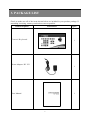
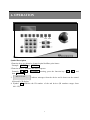
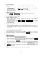
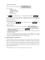
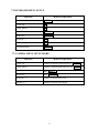
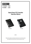
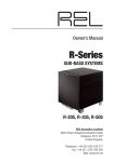
Control Keyboard User Manual Contents 1. SAFETY PRECAUTIONS .......................................................................................................... 1 2. FEATURES .................................................................................................................................. 2 3. PACKAGE LIST.......................................................................................................................... 3 4. NAME AND FUNCTION OF EACH PART............................................................................... 4 4.1 FRONT PANEL.................................................................................................................... 4 4.2 REAR PANEL ...................................................................................................................... 5 5. BASIC CONFIGURATION......................................................................................................... 6 6. OPERATION................................................................................................................................ 7 6.1 SINGLE DEVICE OPERATION ......................................................................................... 8 6.1.1 SELECT and SWITCH DEVICE ................................................................................ 8 6.1.2 CAMERA OPERATION and ZOOM CONTROL ...................................................... 8 6.1.3 FOCUS CONTROL..................................................................................................... 8 6.1.4 PRESET POINT SETUP ............................................................................................. 9 6.1.5 CALL PRESET POINT ............................................................................................... 9 6.1.6 CHANGE PRESET POINT......................................................................................... 9 6.1.7 PATTERN RUN ........................................................................................................... 9 6.1.8 AUTO SCAN ............................................................................................................. 10 6.1.9 CAMERA FUNCTION SETUP ................................................................................ 10 6.1.10 KEYBOARD FUNCTION SETUP......................................................................... 10 6.2 KEYBOARD CONNECTION ........................................................................................... 11 6.2.1 SYSTEM CONNECTION......................................................................................... 12 6.2.2 KEYBOARD COMMUNICATION PROTOCOL.................................................... 12 6.2.3 KEYBOARD ID MANAGEMENT .......................................................................... 12 7. SIMPLE OPERATION GUIDE................................................................................................. 13 7.1 NORMAL OPERATION MODE ....................................................................................... 13 7.2 KEYBOARD MENU SETUP ............................................................................................ 14 7.3 CAMERA MENU SETUP MODE ..................................................................................... 14 8. SPECIFICATION....................................................................................................................... 15 The author assumes no responsibility for any errors or omissions that may appear in this document nor does the author make a commitment to update the information herein. VER.: 1.0, P/N: R040163 1. SAFETY PRECAUTIONS CAUTION RISK OF ELECTRIC SHOCK. DO NOT OPEN! CAUTION : TO REDUCE THE RISK OF ELECTRICAL SHOCK, DO NOT OPEN COVERS (OR BACK). NO USER SERVICEABLE PARTS INSIDE. REFER SERVICING TO QUALIFIED SERVICE PERSONNEL. It is advised to read the Safety Precaution Guide through carefully before operating the product, to prevent any possible danger. WARNING: This symbol is intended to alert the user to the presence of un-insulated “ dangerous voltage”. CAUTION: This symbol is intended to alert the user to presence of important operating and maintenance (Servicing) instructions in the literature accompanying the appliance. Disposal of Old Electrical & Electronic Equipment (Applicable in the European Union and other European countries with separate collection systems). This symbol on the product or on its packaging indicates that this product shall not be treated as household waste. Instead it shall be handed over to the applicable collection point for the recycling of electrical and electronic equipment. By ensuring this product is disposed of correctly, you will help prevent potential negative consequences for the environment and human health, which could otherwise be caused by inappropriate waste handling of this product. The recycling of materials will help to conserve natural resources. For more detailed information about recycling of this product, please contact your local city office , your household waste disposal service or the shop where you purchased the product. Do not Plug and unplug the power cord, it may result product malfunction. Do not install the product in an environment where the humidity is high. Unless the product is waterproof or weatherproof, otherwise poor image quality may occur. Do not drop the product or subject them to physical shocks. Except for vandal-proof or shockproof product, otherwise malfunctions may occur. Never keep the product to direct strong light. It can damage the product. Do not spill liquid of any kind on the product. If it gets wet, wipe it dry immediately. Alcohol or beverage can contain minerals that corrode the electronic components. Do not install the product in extreme temperature conditions. Use the camera under conditions where temperatures are between 5∘C(41∘F) ~ 45∘C.(113∘F). Be especially careful to provide ventilation when operating under high temperatures. 1 2. FEATURES The control keyboard is able to control the P/T/Z Scanner, Speed Dome Camera, and P/T/Z Receiver. Features are listed below: z Supports CCTV system control. z Supports RS485 control interface, and control distance of up to 4000 feet (1.2 km). z 3-Axis joystick is able to control P/T/Z Scanner, Speed Dome Camera, and P/T/Z Receiver (Up/ Down/ Left/ Right/ Zoom-In/ Zoom-Out). The speed depends on the angle of the joystick, the more you push the joystick, the faster the speed. z Compatible to PELCO D&P protocol. z Optional password protection setup. z Keyboard ID can be setup in the Menu setup. z Able to connect up to 32 Control Keyboards (one master control and the rest are slave controls). One keyboard (whether master or slave keyboard) can control up to 255 Speed Dome Cameras, the master Keyboard may also control any cameras controlled by the slave Keyboard. 2 3. PACKAGE LIST Check to make sure all of the items shown below are included in your product package. If something is missing, contact your dealer as soon as possible. Item Picture Item Description Control Keyboard QTY 1 Power Adaptor: DC 12V 1 User Manual 1 3 4. NAME and FUNCTION of EACH PART 4.1 Front Panel ⑪ ⑫ ⑬ ① ② ⑩ ③ ④ ⑤ ⑥ ⑦ 1 ○ 2 ○ 3 ○ 4 ○ 5 ○ 6 ○ 7 ○ 8 ○ 9 ○ 10 ○ 11 ○ 12 ○ 13 ○ ⑧ 16x2 STN LCD Function Key Camera Select Key Control Keyboard Setup Key Confirm Key Numeric Key Clear Key Iris Control Key Focus control Key 3-Axis Joystick Pattern Run Key Preset Setup Key Call Preset Point Key 4 ⑨ 4.2 Rear Panel 1 Power Jack (DC 12V). ○ 2 RS-485 Connector (for device connection). ○ 3 RS-485 RJ-11 Connector (for device connection). ○ 4 RS-485 Connector (for keyboard connection). ○ 5 Pin No. Definition 1 - 2 - 3 - 4 D+ 5 D- 6 - 5. BASIC CONFIGURATION Simple to install, the system supports connection of numerous devices (Ex.: Speed Dome Camera, P/T/Z Receiver, and etc.) Connect the double twisted cable from the keyboard to the RS-485 terminal, and video signal to the monitor, DVR or multiplexer to complete the main system connection. Control keyboard can connect up to 32 sub-systems to form one control system. Using the main control keyboard, each system can be controlled separately. Sub-system Sub-system RS-485 System Connection Illustration Diagram The system supports connections of numerous Speed Dome Cameras or P/T/Z Receivers, assigning a set of ID (Note! ID numbers ranges from 1~127 and may not be repeated) to setup and control, through control keyboard. ►Connecting the Device Connect terminal D+ of the RS-485 from the control keyboard to terminal D+ of RS-485 DATA IN connector from the device; then connect terminal D- of the RS-485 from the keyboard (the same set of terminal) to the terminal D- of RS-485 DATA IN connector from the device. Connecting more than Two Devices Connect terminal D+ of the RS-485 DATA OUT connector from the previous device to the terminal D+ of the RS-485 DATA IN connector from the next device; then connect terminal D- of the previous device (the same set of terminal) to the terminal D- of RS-485 DATA IN of the next device. ►Connecting the Keyboard Connect terminal D+ of the RS-485 from one keyboard connection port to terminal D+ of RS-485 from the other keyboard connection port; then connect terminal D- of the RS-485 from the keyboard connection port (the same set of terminal) to the terminal D- of RS-485 from the other keyboard. 6 6. OPERATION Symbol Description 1.Function keys are shown by, framed capital boldface print letters. Example: ENTER and MENU . 2.Function key “+” indicates the order sequence. Example: 2 8 + ENTER meaning, press the function key “ 2 “, “ 8 ”, and then ENTER . ⎡ DEVICE 001 : _ ⎤ 3. ⎢ ⎥ , indicate messages from the device and is shown on the control ⎣ ⎦ keyboard LCD display. 4. Symbol N indicates the ID number of the nth device (ID numbers ranges from 001~225). 7 6.1 SINGLE DEVICE OPERATION 6.1.1 SELECT and SWITCH DEVICE Enter the desired device number and press CAM key, the speed dome selected by the ⎡ DEVICE 001 : _ ⎤ user to control will appear on the LCD display: ⎢ ⎥. ⎦ ⎣ 6.1.2 CAMERA OPERATION and ZOOM CONTROL The joystick may control many different devices: Speed Dome Camera, PTZ Receiver, and so on. The movement (Up/ Down/ Left/ Right) of the device depends on the angel of the joystick. Zoom Wide / Zoom Tele z Push the joystick clockwise, for close-up image (narrow the angle of viewing) and release the joystick to stop zooming. z Push the joystick anti-clockwise, for far away image (widen the angle of viewing) and release the joystick to stop zooming. Joystick Control The movement depends on the angel of the joystick (the more you push the joystick, the faster the speed): z Push the joystick up or down, the device will move forward or backward. z Push the joystick left or right, the device moves leftward or rightward. Note! Under zoom mode, the speed movement becomes slow. 6.1.3 FOCUS CONTROL Press FOCUS FAR : focus far and release the key to stop focusing. Press FOCUS NEAR : focus near and release the key to stop focusing. 8 6.1.4 PRESET POINT SETUP The speed dome camera enables 80 preset points. Preset function is to save the address information (such as PTZ pan/tilt, focus and etc) to the memory so that you can quickly adjust the dome and PTZ to the correct position, and when necessary to view life monitoring. Setup Steps: ① Select the desired speed dome camera (please refer to 6.1.1 SELECT and SWITCH DEVICE). ② Use the joystick (on the control keyboard) and move the speed dome camera to the desired preset point. ③ Use the zoom control to adjust the monitoring display. ④ Enter preset number (1~32, 35~82), and press SET PRESET key, the LCD will display ⎡SAVE TO PRESET ⎤ ⎢ ⎥. XXX ? ⎣ ⎦ ⑤ Press SET PRESET key, to enable storage and press CLEAR key to disable storage. * Repeat the steps 1~4 again, to setup more preset points. 6.1.5 CALL PRESET POINT Enter the assigned preset number and press GO PRESET key, the LCD will ⎡GO PRESET : XXX ⎤ display: ⎢ ⎥ , and the speed dome camera will move to that specified ⎣ ⎦ preset point. Example: 1st preset point = th 128 preset point = 1 + 1 GO PRESET 2 8 + GO PRESET 6.1.6 CHANGE PRESET POINT To change the preset point, please follow the setup guide in the “6.1.4 PRESET POINT SETUP”. 6.1.7 PATTERN RUN This function is designed to scan the preset points of the desired group in order (1~32). It memorizes the PTZ movement and camera focus from the starting point at the same interval (Please refer to speed dome user manual for group setup). Start Pattern Run ⎡ DEVICE 001 : _ ⎤ Under control mode (assume device=1), when the LCD displays: ⎢ ⎥, ⎣ ⎦ enter the desired group number to be setup (Assume group=1, then enter 1), then press PATTERN key, to activate pattern run mode in group number 1. * Preset point group number may differ depending on the speed dome camera type. Stop Pattern Run Push Joystick to any direction. 9 6.1.8 AUTO SCAN Activate Auto Scan Under control mode (assume device=1), when the LCD displays: ⎡ DEVICE 001 : _ ⎤ ⎢ ⎥ , enter 9 9 + G0 PRESET key, the speed dome camera ⎣ ⎦ will slowly proceed 360° auto scan. Deactivate Auto Scan Enter 9 6 + GO PRESET key, or push the joystick to stop auto scan. 6.1.9 CAMERA FUNCTION SETUP Enter Camera Setup Menu Under control mode (assume device=1), when the LCD displays: ⎡ DEVICE 001 : _ ⎤ 5 + SET PRESET key, to enter ⎢ ⎥ , enter F2 / 9 ⎣ ⎦ camera setup menu.. Camera Operation Setup Enter camera function setup menu to setup the camera function (Please refer to “7.3 Camera Menu Setup Mode” and for more detail refer to speed dome user manual for group setup). 6.1.10 KEYBOARD FUNCTION SETUP Control keyboard supports keyboard ID, operation mode (PELCO P or PELCO D), communication protocol, and password setup. Press keyboard setup menu. MENU key to enter control Password Confirm Before entering the setup menu, password is requested. ⎡ ENTER PASSWORD : ⎤ When LCD displays: ⎢ ⎥ , enter password and press ENTER ⎣ _ ⎦ key, system confirms the password. To enter menu setup correct password (if none was set, leave it blank and press ENTER key) has to be entered. When password entered is ⎡ DEVICE 001 : _ ⎤ incorrect, the system will return to previous display: ⎢ ⎥ . When ⎣ ⎦ MENU key has been accidentally pressed, press again to exit the CONTROL KEYBOARD MENU SETUP display. * When password is locked or forgotten, please contact your local dealer. 10 Select Operation Mode ⎡ → KEYBOARD ID ⎤ Enter menu setup, LCD will display: ⎢ ⎥. ⎣ OPERATION MODE⎦ Five item setups: KEYBOARD ID OPERATION MODE COMM PARAMETER BUZZER SET PASSWORD Use ↑ ↓ key to move the cursor “→” to the desired item and press ENTER key to enter item setup. Due to LCD display size, each time only two items are displayed and not all five items at once. When necessary, LCD display will auto roll-down to display the next two items and so on. Operation Mode Setup Enter setup menu, use ← return to main menu setup. → key to change the setup. Press ENTER key to Password Setup ⎡ NEW PASSWORD : ⎤ Enter password item setup. When LCD displays: ⎢ ⎥ , use ⎣ _ ⎦ number key, enter new password and press ENTER key. When LCD displays: ⎡ CHECK PASSWORD : ⎤ ⎢ _ ⎥ , re-enter the new password. After confirmation, password ⎣ ⎦ setup will be complete. * Please do not setup password unless necessary, because only with the correct password can you enter KEYBOARD FUNCTION SETUP menu. Therefore, it is utterly important to remember your password once it has been setup. 6.2 KEYBOARD CONNECTION Control keyboard supports string connection and one keyboard controls multiple system platforms (one keyboard control system includes a keyboard that controls one group of devices). Slave keyboard controls only a single device, master keyboard controls a single device, as well as the entire slave keyboard and the cameras connected to the slave keyboards. Master keyboard ID No. must be setup to 00, and slave keyboard ID No. can be setup to any ID No. from 01~31. * Note that the ID No. may not be repeated, otherwise error may occur. 11 6.2.1 SYSTEM CONNECTION According to the diagram below, setup the master ID to 00 and complete the slave control keyboard setup. 連接至 Speed Dome 連接至 Speed Dome 功能同控制埠 D- D+ D- D+ 功能同控制埠 D- D+ D- D+ 控制埠 RS-485 D- D+ D- D+ D- D+ D- D+ RJ-11 RJ-11 控制埠 RS-485 鍵盤串接埠 RS-485 MASTER: ID = 00 鍵盤串接埠 RS-485 SLAVE: ID = 1~31 System Connection Diagram 6.2.2 KEYBOARD COMMUNICATION PROTOCOL The whole system uses the same operation mode (Pelco P/ Pelco D) and communication protocol. Setup 2 parameters for the master keyboard, press F5 key during operation mode to transfer the parameter to all slave keyboards within the system (no need to setup individually). This enables one to know straight away if there is more than one ID No. setup as 00 (but impossible to find out in slave keyboard). When there are repeated ID No ⎡ MASTER DUPLEX ⎤ setups as 00, LCD will display: ⎢ ⎥ and starts flashing until it has ⎣ CHECK SYSTEM ⎦ been deactivated (press any key to deactivate), otherwise no command will be accepted. 6.2.3 KEYBOARD ID MANAGEMENT Control keyboard display differs according to master/ slave. Master keyboard displays: ⎡ DEVICE 001 : _ ⎤ ⎢G : 00 ⎥ . G indicates group and 00 indicates the ID No. of the slave keyboard that has ⎣ ⎦ been controlled. Thus also mean that the master keyboard has control on the cameras connected to it (master keyboard ID No. = 00). When using master keyboard to control other groups of slave keyboards, please enter slave keyboard ID No. and then press F1 key (the master keyboard will request slave keyboard to release authority). After the slave keyboard has released ⎡CONTROL BY ⎤ full authority to the master keyboard, LCD displays: ⎢ ⎥ slave keyboard ⎣ MASTER ⎦ looses all control authority until master keyboard returns the authority back to the slave keyboard. When the master keyboard calls to control other slave keyboards it will return the control authority to the previously controlled slave keyboard (when the master keyboard receives the full authority, it is able to fully control all cameras that was controlled by the slave keyboard). To return control authority to the slave keyboard, enter master keyboard ID No. (00) and then press F1 key, to release slave keyboard control authority. 12 7. SIMPLE OPERATION GUIDE 7.1 NORMAL OPERATION MODE Functions P/T/Z Control Method of Operation Upward Rotation (upward image monitoring) Downward Rotation (downward image monitoring) Leftward Rotation (leftward image monitoring) Rightward Rotation (rightward image monitoring) Zoom Tele Zoom Wide Push the Joystick Forward Push the Joystick Backward Push the Joystick Leftward Push the Joystick Rightward Push the Joystick Clockwise Push the Joystick Counterclockwise Select device No. Key+ CAM Manual Operation Focus Far FOCUS FAR Manual Operation focus Near FOCUS NEAR Iris Control to Bright IRIS OPEN Iris Control to Dark IRIS CLOSE Enter Preset No. (1~32, 35~82) Preset Point Setup Press Key: SET PRESET Enter Preset No. (1~32, 35~82) Call Preset Point Press Key: GO PRESET Enter Group No. (1~6) Start Pattern Run Mode Press Key: Stop Pattern Run Mode PATTERN Push Joystick to any direction Enter 99 Start Preset Mode Press Key: GO PRESET Stop Preset Mode Push Joystick to any direction Enter Camera Menu Selection Mode Press Key: Enter 95 Press Key: 13 F2 or SET PRESET 7.2 KEYBOARD MENU SETUP Functions Method of Operation Enter Main Menu MENU Cursor Up ↑ Cursor Down ↓ Menu Enter ENTER Menu Exit ENTER Decrease (-) ← Increase (+) → Exit Main Menu MENU 7.3 CAMERA MENU SETUP MODE Functions Method of Operation Cursor Up Push the Joystick Forward FOCUS Cursor Down Push the Joystick Backward FOCUS Menu Enter IRIS OPEN Menu Exit IRIS CLOSE Decrease (-) Push the Joystick to the Left Increase (+) Push the Joystick to the Right 14 NEAR FAR 8. SPECIFICATION Power DC12 V ±10% (Recommendation 12 ±0.5 V) Power Consumption 400mA RS-485 Pelco P & Pelco D Default(depends on chose protocol) 2400,N,8,1 2400,O,8,1 2400,E,8,1 4800,N,8,1 4800,O,8,1 4800,E,8,1 9600,N,8,1 9600,O,8,1 9600,E,8,1 Control Device 255 Device Manual P/T/Z Control Pan Right / Left Tilt Up / Down Pan On / Off Sequence On / Off Auto Lens Control Camera Control ZOOM WIDE / TELE FOCUS NEAR / FAR IRIS OPEN / CLOSE Preset Point 80 (1~32, 35~82) Camera Setup Available Dimension 296x190.4x52.7mm ( W x D x H ) Operating Temp. 0°~45°C Weight 1.4 Kg (Note: Design and Specifications are subject to change without notice.) 15