1
COMMANDER
UNIVERSAL IRRIGATION REMOTE CONTROL
FCC REGULATIONS
The user of this remote control device does not need an FCC license.
The Receiver has been tested and found to comply with the limits for a
Class A digital device, pursuant to Part 15 of the FCC Rules. The Transmitter has been tested and found to comply with Part 95 Subpart E. These
limits are designed to provide reasonable protection against harmful interference when the equipment is operated in a commercial environment.
Canadian Certification #32151021261
2
800-275-8558 www.irrigationremotes.com
INTRODUCTION
Congratulations! You have just purchased the most advanced
irrigation remote control available - the TRC Commander.
We welcome you to the growing family of thousands of satisfied
TRC Irrigation Remotes product users who appreciate the importance of high standards, product quality and timely service.
The TRC Commander is TRC Irrigation Remotes' 6th generation of
remote control products introduced since 1982. All of our remote
control products do not require site surveys, base stations or FCC
licensing.
WARRANTY
All TRC Irrigation Remotes’ products carry a “THREE YEAR
WARRANTY”.
For three years from the date of purchase. TRC Irrigation Remotes
will repair or replace any of its products or parts to be found defective
as to workmanship or materials. This warranty does not extend to
damage to a TRC Irrigation Remotes product resulting from misuse,
neglect or abuse, improper installation or accident.
This warranty extends only to an original user of TRC Irrigation
Remotes product(s). In no event shall TRC Irrigation Remotes be
liable for incidental or consequential damages.
All implied
warranties are limited in duration to three years following date of
purchase. These exclusions or limitations apply only in those
states where permitted by law.
800-275-8558 www.irrigationremotes.com
3
Models and Description
Transmitter
TRC Commander Transmitter is the hand-held part of your
remote system. Any 24VAC solenoid valve sprinkler system
equipped with a TRC Universal Receiver or TRC Permanent
Receiver Card can be operated with this Transmitter. The Transmitter operates on one 9-volt alkaline replaceable battery.
Note: The battery must be alkaline or the transmitter will
not operate.
Receivers
Universal 32 Station DCI Receiver is compatible with all
24VAC solenoid valve sprinkler systems and is capable of operating 32 stations per controller. This portable Receiver connects easily with a permanent connector hard wired to the terminal strip and a custom housing mounted on the controller for
quick plug in.
Permanent Receiver Cards install easily and permanently into
the controller. Installing Permanent Receiver Cards allows all
zones of the controller to be operated. Each Card comes with
internal and external antennas w/mounting hardware. Maximum
range is achieved by installing the external antenna to the controller cabinet.
4
800-275-8558 www.irrigationremotes.com
Special Features
• Connects to any 24VAC sprinkler system
• Silent Running
-Turn off all of the zones from 1 - 7 days
• Adjustable Time Duration
-2 Minutes to 2 Hours (default 20 minutes)
• Multiple Receiver operation from a single Transmitter
- Field programmable dipswitches offer
199 unique Receiver numbers
• Programmable security codes
-9999 different security group codes
• Audible low power indicator
-Field replaceable 9 volt battery
• Master Valve disable key
-Pump Start/Master Valve
Permanent Receiver Cards are available for the following
controllers:
Rain Bird ESP MC® (NOT Compatible with SAT Controllers)
Rain Bird ESP LX®
Irritrol Dial & MC®
Superior Sterling®
HIT Logic 2 & 3®
Griswold IDC®
Weathermatic®
Hunter®
800-275-8558 www.irrigationremotes.com
5
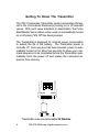
Getting To Know The Transmitter
The TRC Commander Transmitter sends a proprietary FM signal to the Commander Receiver(s) turning on or off selected
valves. With each valve activation or deactivation, the Pump
Start/Master Valve station, when used, is automatically turned
on or off unless "MV Off" has been pressed.
The Transmitter is designed for minimal power consumption
to extend the life of the battery. The Transmitter power is
normally off. Once any key has been pressed, power is automatically turned on for about ten seconds to allow your command sequence to be completed before the Transmitter automatically turns the power off and erases the command sequence from memory.
Transmitter uses one replaceable 9V Alkaline
6
800-275-8558 www.irrigationremotes.com
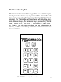
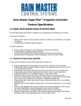
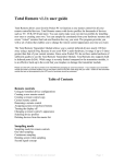
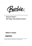
The Transmitter Key Pad
The Commander Transmitter keypad has an audible beep to
clearly indicate when a key is pressed. The Transmitter will
beep once when a Number Key or the Receiver Number Key is
pressed. The Transmitter will beep twice, with about two seconds between beeps, after a transmit key is pressed for ("VALVE
ON", "VALVE OFF", "AUTO UP", "AUTO BACK", "M-V OFF"
or "TIME"). The first beep indicates that the transmission is
starting, and the second beep indicates that transmission has
been completed.
COMMANDER
AUTO
UP
AUTO
BACK
1
2
3
4
5
6
7
8
9
VALVE
ON
0
VALVE
OFF
TIME
REC
#
MV
OFF
800-275-8558 www.irrigationremotes.com
7
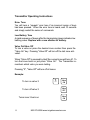
Transmitter Operating Instructions
Error Tone
You will hear a “squawk” error tone if an incorrect series of keys
has been pressed. When the error tone is heard, wait 10 seconds
and simply restart the series of commands.
Low Battery Tone
A rapid sequence of beeps after the transmission beep indicates low
battery power. Replace with a new alkaline 9V battery.
Valve On/Valve Off
To turn a valve on press the desired zone number then press the
"Valve On" key. Pressing "Valve Off” will turn off the last zone activated.
When "Valve Off" is pressed by itself the current zone will turn off. To
turn that zone back on just press "Valve On". The Transmitter remembers which valve you were testing.
Pressing "0", "Valve Off" will turn off all zones.
Example:
To turn on valve 3:
8
3
Valve
ON
To turn off valve 3:
Valve
OFF
Turns zone 3 back on:
Valve
ON
800-275-8558 www.irrigationremotes.com
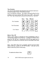
Auto Up/Auto Back
These functions allow forward and backward advancement
through each station. This will turn on the next sequential
station number.
To operate press:
AUTO
UP
OR
AUTO
BACK
Multiple Zones
Press the "9" key before a two digit zone number to turn on a
multiple zone. Example: "903", "Valve On" will turn zone 3 on.
You may have up to six multiple zones on at a time and a single
zone plus a master valve. Multiple zones cannot be changed
by the "Auto Up" or the "Auto Back" functions, but they can have
an independent time duration.
A station registered for multiple mode operation will not be turned off
automatically when other stations on the same Receiver are turned
on. Also, the single mode station will not be automatically turned off
when multiple mode stations are turned on. If you try to turn on a
seventh multiple mode valve, the first multiple mode valve turned on
will be automatically turned off.
WARNING: Make sure your controller has adequate power to
operate the number of multiple stations you intend to have on
at one time. Otherwise, you may overload the circuit breaker
at your controller.
Adding zone 2:
9
0
2
Valve
ON
Adding zone 32:
9
3
2
Valve
ON
To turn all zones off:
0
Valve
OFF
800-275-8558 www.irrigationremotes.com
9
Time Duration
You can set a time duration anywhere from two minutes to two hours.
Press three digits of time in the following format:
Hour, Tens Minutes, Minutes. The range of allowed entries for time
duration is from two minutes "002" to two hours "200". Then press
the "Time" key, followed by the desired zone # and then "Valve On."
Hour
Tens
Minutes
For 2 minutes:
0
0
2
TIME
For 20 minutes:
0
2
0
TIME
For 2 Hours:
2
0
0
TIME
Master Valve Off
When a valve station is activated the Pump Start/Master Valve is
automatically enabled by the Receiver. To disable the Master Valve
press the "MV Off" key. Pressing the "MV Off" key again prior to
turning on any stations at a Receiver will turn the Master Valve back
on.
Note: Using "99" "Valve On” to manually operate the Pump Start/
Master Valve will override the "MV Off" function. It will also run the
Master Valve/Pump Start continuously.
To disable the Master Valve:
10
MV
OFF
800-275-8558 www.irrigationremotes.com
Operating the Pump Start/Master Valve
When in the automatic mode, the Pump Start/Master Valve is automatically activated when a valve station is turned on. You can manually turn on the Pump Start/Master Valve by pressing "99" "Valve
On". IF YOU MANUALLY TURN ON THE PUMP START/MASTER
VALVE STATION, YOU MUST MANUALLY TURN IT OFF AGAIN.
There is no default time with this function. The Pump Start/MV will
stay on until "0" "Valve Off" or "99" "Valve Off" command is received.
Press the two digits "99" "Valve On" to select only the Pump Start/
Master Valve station. To turn off the pump start/master valve station
press the two digit "99" "Valve Off" key to deactivate.
To turn Master Valve off:
9
9
VALVE
To turn Master Valve on:
9
9
VALVE
ON
Receiver Number
The TRC Commander Transmitter can operate as many as 199
Permanent Receivers on each group code. To designate
Receiver press a desired Receiver number and "Rec #" key.
Setting to Receiver number 3:
3
REC
#
800-275-8558 www.irrigationremotes.com
11
Silent Running Feature (Rain Off)
This feature allows user to shut down the controller remotely by
disconnecting valve common similar to a rain switch. The controller can be disabled for 1 to 7 days or indefinitely.
The Receiver Card interrupts the signal from the controller to the
valves and shuts the system down without having to change programming. Pressing "9" then the desired number of days, then
"Valve Off" will program the Silent Running feature.
Silent Running (Rain Off) codes:
90 Valve Off
Infinite
91 Valve Off
1 Day
92 Valve Off
2 Days
93 Valve Off
3 Days
94 Valve Off
4 Days
95 Valve Off
5 Days
96 Valve Off
6 Days
97 Valve Off
7 Days
0 Valve Off
Clear
Pressing "0" then "Valve Off" will clear all and reset the Receiver
Card, erasing all Silent Running programs.
12
800-275-8558 www.irrigationremotes.com
Reprogramming the Transmitter
You must first wait at least 10 seconds after any key has been
pressed before reprogramming. The following example reprograms the Transmitter to the factory defaults. YOU DO NOT NEED
TO CHANGE ANYTHING TO MAKE YOUR UNITS OPERATE!
Step 1:
Step 2:
8
8
5 2
1
4 1
0 0 0
Step 3:
REC
#
1
REC
#
1
REC
#
Step 1 gives you access to the Transmitter’s memory. Step 2 sets
the Group Code to “0001”. Step 3 sets the Receiver Number to “1”.
The units come from the factory set to communicate with each other
on Group Code #1, and Receiver #1. YOU DO NOT NEED TO
CHANGE ANYTHING TO MAKE YOUR UNITS OPERATE!
You only need to reprogram your Transmitter if you change the
dipswitch settings on the Receiver. If you choose to do so, you will
need to follow the steps above, making sure you change the Group
Code and Receiver Number (steps 2 and 3) to match that of the
Receivers, as explained on the next page.
If the battery is removed for more that 2 minutes (or if it has died)
you only have to reprogram the Transmitter if you have previously
changed your Group Code or Receiver Number settings from the
factory defaults. The Transmitter will remember the Group Code and
Receiver Number for approximately 2 minutes with battery removed
for replacement.
800-275-8558 www.irrigationremotes.com
13
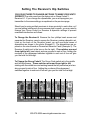
Setting The Receiver’s Dip Switches
YOU DO NOT NEED TO CHANGE ANYTHING TO MAKE YOUR UNITS
OPERATE! The units come from the factory set on Group Code # 1,
Receiver # 1. If you change the dipswitches, you must reprogram you
transmitter to the same settings, as explained on the previous page.
Should you be using multiple receivers in close proximity to each other, or if
you are getting interference from someone else’s remote, you may need to
change your Group Code # or Receiver # dipswitch settings to prevent
unwanted interference as follows:
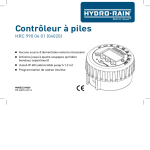
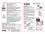
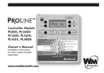
To Change the Receiver #: Remove the four phillips head screws and
separate the Receiver case to expose the Receiver number dipswitch set.
Look on the back of the Receiver board; you will see three boxes of
dipswitches as shown in the photo (Example 1). The dipswitches are exposed on the circuit board on Permanent Receiver Cards (Example 2). The
Receiver # switch set is the box on the far right. The switches are read
from right to left, (see below) and are grouped in sets of four. Adding the
numbers of the depressed switches together in each set of four will give
you the total for that digit.
To Change the Group Code #: The Group Code switch set is the middle
and left-hand boxes. These switches also read from right to left,
starting with the middle box and working toward the left (see below) and are
also grouped in sets of four. Adding the numbers of the depressed
switches together in each set of four will give you the total for that digit.
14
800-275-8558 www.irrigationremotes.com
EXAMPLE 1: Factory Default - Universal Receiver shown
Group Code Switch Set is switched to Group Code #1,
Receiver Switch Set is switched to Receiver #1
Group Code Switch Set
Receiver # Switch Set
EXAMPLE 2: Factory Default - Permanent Receiver Card shown
Group Code Switch Set is switched to Group Code #1,
Receiver Switch Set is switched to Receiver #1
Group Code Switch Set
Receiver # Switch Set
EXAMPLE 3: Permanent Receiver Card shown
Group Code Switch Set is switched to Group Code #1,
Receiver Switch Set is switched to Receiver #2
Group Code Switch Set
Receiver # Switch Set
EXAMPLE 4: Permanent Receiver Card shown
Group Code Switch Set is switched to Group Code #2,
Receiver Switch Set is switched to Receiver #3
Group Code Switch Set
Receiver # Switch Set
800-275-8558 www.irrigationremotes.com
15
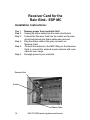
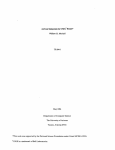
Receiver Card for the
Rain Bird ESP MC
Installation Instructions:
Step 1:
Step 2:
Step 3:
Step 4:
Step 5:
Step 6:
Remove power from controller first!
Unplug the ribbon cable from the main circuit board.
Connect the Receiver Card into the socket on the main
circuit board where the ribbon cable was removed.
Plug the ribbon cable in the gray connector on
Receiver Card.
Connect the antenna to the BNC fitting on the Receiver
Card or connect the external mount antenna with coax
cable for max. range.
Re-apply power to your controller.
Receiver Card
Socket
Ribbon Cable
16
800-275-8558 www.irrigationremotes.com
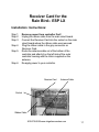
Receiver Card for the
Rain Bird ESP LX
Installation Instructions:
Step 1:
Step 2:
Step 3:
Step 4:
Step 5:
Step 6:
Remove power from controller first!
Unplug the ribbon cable from the main circuit board.
Connect the Receiver Card into the socket on the main
circuit board where the ribbon cable was removed.
Plug the ribbon cable in the gray connector on
Receiver Card.
Route the antenna cable out of the bottom of the
controller and attach it on the left side of the outer
controller housing with the Velcro supplied on the
antenna.
Re-apply power to your controller.
Receiver Card
Antenna Cable
Socket
Ribbon Cable
800-275-8558 www.irrigationremotes.com
17
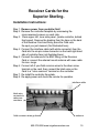
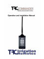
Receiver Cards for the
Superior Sterling
Installation Instructions:
Step 1: Remove power from controller first!
Step 2: Remove the controller faceplate by unscrewing the
cross-recessed screws on each side.
Step 3: Clean upper left, inner side panel (inside controller, behind
front panel). Remove the backing from the tape on the back
of the Receiver Card and firmly press the Card onto
the spot you just cleaned. (Not illustrated here).
Step 4: Connect the interface cable (with white connector) from the
Card into the six pin molex connector on the back right-hand
side of controller face (not illustrated here).
Step 5: Connect the antenna to the BNC fitting on the Receiver
Card or connect the external mount antenna with coax cable
for max. range.
Step 6: Connect all of your field common wires to the silver screw
terminal on the card, then connect the black wire on the
Card to a "valve common" terminal on the controller.
Step 7: Re-install the controller face plate.
Step 8: Re-apply power and check the remote for operation.
interface cable
black wire
connects to
valve common here
field common wires go here
800-275-8558 www.irrigationremotes.com
antenna
19
Receiver Cards for the Irritrol
MC and Dial
Installation Instructions:
Step 1: Remove power from controller first!
Step 2: Remove the controller faceplate by unscrewing the
cross-recessed screws on each side.
Step 3: Clean upper left, inner side panel (inside controller, behind
front panel). Remove the backing from the tape on the back
of the Receiver Card and firmly press the Card onto
the spot you just cleaned. (Not illustrated here).
Step 4: Connect the interface cable (with white connector) from the
Card into the six pin molex connector on the back right-hand
side of controller face (not illustrated here).
Step 5: Connect the antenna to the BNC fitting on the Receiver
Card or connect the external mount antenna with coax cable
for max. range.
Step 6: Connect all of your field common wires to the silver screw
terminal on the card, then connect the black wire on the
Card to a "valve common" terminal on the controller.
Step 7: Re-install the controller face plate.
Step 8: Re-apply power and check the remote for operation.
interface cable
black wire
connects to
valve common here
field common wires go here
20
800-275-8558 www.irrigationremotes.com
antenna
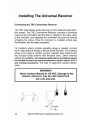
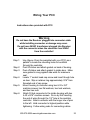
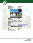
Wiring Your PCC
Instructions also provided with PCC.
Warning
Do not have the Receiver plugged into connector cable
while installing connector or damage may occur.
Do not have 24VAC transformer plugged into Receiver
with the connector when the connector has 24VAC
from the controller!
Step 1:
Step 2:
Step 3:
Step 4:
Step 5:
Step 6:
Use (figure 4 from the pamphlet with your PCC) as a
pattern to locate the mounting holes to be drilled
through the controller.
Peel off sticker and attach gasket on back of housing.
Peel off sticker and attach gasket to inside door. Make
sure gasket is snug against side walls for maximum
seal.
Locate 1" socket head cap screw and insert though hole
on door. Slip on retainer ring approximately 3/16" from
threaded end of cap screw.
Mount housing to controller using two 6-32 x 3/4"
machine screws, two flat washers, two lock washers,
and two hex nuts.
Attach D-Sub connector to the inside housing with two
4-40 x 9/16" machine screws. Do so by first inserting
the end of wires through the 1/2" hole in the sprinkler
controller. Attach connector with the longer row of pins
to the left. Hold connector to highest position while
tightening. Follow wiring code for connecting cables.
800-275-8558 www.irrigationremotes.com
23
Direct Controller Interface Cable
For the Irritrol MC, Dial and Superior
To connect the DCI-1 Cable:
Remove the faceplate from the controller. Hook the molex receptacle directly to the 6 pins on the circuit board of controller.
Do not force it in--it should fit only one way. Punch knockout
hole from the bottom of the controller. Position circular end of
DCI-1 cable through knockout hole and attach with screws. This
connector should remain with controller. Replace controller faceplate.
To connect the DCI-2 Cable:
WARNING
TRC COMMANDER RECEIVER MUST BE
CONNECTED TO 37-PIN CLAMSHELL BEFORE
CONNECTING DCI-2 CABLE TO CONTROLLER.
First connect the 37-pin clamshell directly to the TRC Commander
Receiver. To operate the Receiver, attach the DCI-2 circular plug
to the DCI-1 connector at the controller knockout location. Align
pins and twist connector on with a clockwise motion. Do not
force it in--it should fit only one way. This cable is removable and
allows portable hookup at each controller.
24
800-275-8558 www.irrigationremotes.com
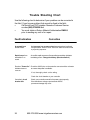
Trouble Shooting Chart
Use the following chart to determine if your problem can be corrected in
the field. If you have a problem that cannot be fixed in the field:
x
Call the toll free TRC Irrigation Remotes Customer Service
number (800) 275-8558 and
x
You must obtain a Return Material Authorization RMA #
prior to sending any unit in for repair.
Fault Indication
A squawk from
the transmitter.
Correction
An improper key sequence has been entered and confused
microprocessor. Press "0" then "Valve Off" and then continue with
a proper key sequence.
Rapid beeps from
transmitter or no
sound.
An audible rapid sequence of beeps after transmission indicates
low battery power. Change the battery. (Must be alkaline!)
Receiver "Power On" Check the 24VAC pins on the controller connector with a volt meter
indicator does not
to ensure that power is available.
come on.
If not, thoroughly check out the wiring.
Check the circuit breaker at your controller.
Controller's circuit
breaker fails.
26
Check your controller manual for its power output capacity.
If the transformer voltage output exceeds 28VAC
permanent damage may occur.
800-275-8558 www.irrigationremotes.com
Fault Indication
Receiver fails to
respond, but the
power light is on.
Correction
Check if the Receiver number was inadvertently
changed. Reprogram the Transmitter codes to match
the Receiver codes. (Press "1", "REC #")
Check the Group Code and Receiver Code dipswitches
on the Receiver. Reprogram the Transmitter to match
the Receiver codes. (See page 13).
Receiver’s “Valve
On” indicator lights
during initial test,
but no valve or wrong
valve comes on.
Use an ohmmeter to check that your connector's
wire assignment matches your controller's valve
assignment.
Rain Bird’s RC series
controller advances
to the first station with
remote operation.
Install the RC Series Controller Isolation Relay
(Part #02002).
Receiver turns off when
one station is activated.
Check solenoid. Current drain is more than 3 amps
and is tripping the resetting fuse.
Short Range
Ensure that the antennas are firmly attached to the
Receiver and Transmitter.
Ensure that the antenna is clear from obstructions. The
three feet immediately surrounding the antenna are the
most crucial and should be kept clear of obstructions,
power lines, or electrical conduits, electric motors etc.
Keep the antenna as high as possible on the controller
and avoid situations where the antenna can be
shadowed by buildings or large metal structures.
Ensure that the Receiver's antenna is as far away from
electric motors, V.F.D.'s and overhead powerlines as
this type of equipment causes interference.
800-275-8558 www.irrigationremotes.com
27
32 Station Connector Wiring Color Codes
Valve
Wire Color
Valve
Wire Color
1
Black
19
Green w/ black and white stripe
2
White
20
Orange w/ black and white stripe
3
Red
21
4
Green
22
Black w/ red and green stripe
5
Orange
23
White w/ red and green stripe
6
Blue
24
Red w/ black and green stripe
7
White w/ black stripe
25
Green w/ black and orange stripe
8
Red w/ black stripe
26
Orange w/ black and green stripe
9
Green w/ black stripe
27
Blue w/ white and orange stripe
10
orange w/ black stripe
28
Black w/ white and orange stripe
11
Blue w/ black stripe
29
White w/ red and orange stripe
12
Black w/ white stripe
30
Orange w/ white and blue stripe
13
Blue w/ red stripe
31
White w/ red and blue stripe
14
Red w/ green stripe
32
Black w/ white and green stripe
15
Orange w/ green stripe
16
Black w/ white and red stripe
Com
Orange w/ red stripe
17
White w/ black and red stripe
M.V.
Green w/ white stripe
18
Red w/ black and white stripe
24 V
Blue w/ white stripe
Blue w/ black and white stripe
1(800) 275-8558
www.irrigationremotes.com