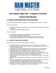
1
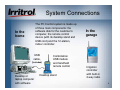
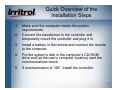
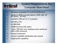
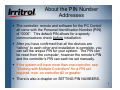
PC Control
Installation and
Startup
1
System Connections
The PC Control system is made up
of three main components: the
software disk for the customer’s
computer, the remote control
device (with its desktop stand and
USB cord) and the 12-station,
indoor controller.
In the
home
USB
cable,
(included)
Desktop or
laptop computer
with software
Combination
USB module
and handheld
remote control
Desktop stand
In the
garage
Irrigation
controller
with built-in
2-way radio
2
The PC Control System’s
User’s Manual
The first sections of this manual are a guide to the
installation of the PC Control system with one 12station controller and its initial setup.
The later sections of the manual contain detailed
information on specific topics for reference, such as:
Manual On and Off, Rain Delay and Sensor Hold
Per zone controls
What each menu page provides
The Scheduling Advisor™
Using schedules (opening, saving, changing, etc.)
Installation and setup for multiple controllers
FCC and UL information
3
Quick Overview of the
Installation Steps
1.
Make sure the computer meets the system
requirements.
2.
Connect the transformer to the controller and
temporarily mount the controller and plug it in.
3.
Install a battery in the remote and connect the remote
to the computer.
4.
Put the system’s disk in the computer’s CD-ROM
drive and (at the user’s computer location) start the
communications check.
5.
If communication is “OK”, install the controller.
4
System Requirements the
Computer Must Meet
Windows compatible PC with CD-ROM drive
Windows 98SE (second edition), 2000, ME, NT,
XP Home, XP Prof.
Available USB port (1.0 or greater)
900 MHz CPU
64 MB RAM
20MB free hard disk space
1024 x 768 64K color display/monitor preferred
(800 x 600 minimum)
Mouse & keyboard
Internet capability (preferably high speed)
Digital photo capability
5
About the PIN Number
Addresses
The controller, remote and software for the PC Control
all come with the Personal Identification Number (PIN)
of “0000”. This default PIN allows for a speedy
communications check before installation.
After you have confirmed that all the devices are
“talking” to each other and installation is complete, you
can set the unique PIN for your system. The PIN can
be reset from the computer, however the remote’s PIN
and the controller’s PIN can each be set manually.
If the system will have more than one controller, see
“Working with Multiple Controllers” for a PIN set
required, now, on controller #2 or greater.
There is also a chapter on SETTING PIN NUMBERS.
6
Check the Range:
Preparing the Controller
Connect the controller’s transformer following these steps:
Do not plug in the transformer!
Remove the access cover from the controller by pushing in on the
finger grips on both sides and sliding the cover forward and off the
controller.
Slip the transformer’s 3-wire cord through the small hole on the
left side of the bottom of the controller’s case.
Pull 6 inches of cable into the controller and tie a loose, half knot
to prevent it from being pulled back out.
With a screwdriver, connect the red wire to the lower left hand
terminal on the terminal strip, the black wire to the second from
the left and the green wire to the third.
Connect the 9-volt battery to the battery clip and replace the
access cover.
Temporarily mount the controller on a short screw or nail in the
proposed location and then plug it in to prepare for the
communications check.
7
Check the Range:
Preparing the Remote
With the remote face down, use a fingernail to open the catch
to the battery compartment cover and set the cover aside.
Bring out the battery clip and connect the 9-volt battery.
Insert the battery into the compartment and without crimping
them, carefully put the wires back.
Insert the cover’s two tabs under the lower lip of the
compartment and snap the cover’s latch back in place.
For a close range check, press and release any button on the
remote to “wake it up.” Wait two seconds (all segments in the
display will be illuminated) while the remote searches for the
controller. The default PIN will allow communication.
When the controller’s status appears, “AUTO” or “OFF”, with
the signal indicator, the two devices are “talking”.
8
Checking the Range from
Computer to Computer
In the following steps, you will check to see if the
system’s range will work for your application:
At the user’s usual computer location within the home, use
the supplied cord to connect the remote to a USB port on the
computer. On the side of the remote, the “plug” for the USB
compartment is designed to be pulled outward by its short,
upper tab to expose the mini-USB connector.
After connecting the remote to the computer, place the
remote in its stand on the same surface as the computer.
If the computer is off, turn on the computer and let it boot up.
Then open the CD-ROM drive, insert the PC Control
system’s CD and close the drive.
9
Your System on Screen
Read the agreement carefully. You must
click the AGREE button to continue.
Click on “My
Computer” and
then click on the
disk drive icon.
Double-click on
the PC Control
file to start it.
A start up
screen will
appear followed
by the License
Agreement &
Privacy Policy.
10
Your System on Screen
When the Software
Installation screen
appears, click on “CDROM” from which to
install the program.
Click NEXT
to proceed.
The next screen is for
installation options. In
most cases, all the
selected options are
desirable.
Click NEXT
to proceed.
11
Your System on Screen
Wait for a few moments
while the program
completes the installation
and instructs you to click
NEXT.
The shortcut icon
appears on your
desktop.
The system overview is the
last screen before the
program is launched.
Make sure the remote is
connected to your
computer and the controller
in the garage is plugged in.
Click NEXT
12
Your System on Screen
Allow the system
20 seconds or so
to establish
communication.
The AUTO ON
tab will appear to
indicate the
controller in the
garage is on.
“Synchronize
Time” and then
“Synchronize
Controller’s
Station Use” text
boxes will
appear.
In each case, left click on the UPDATE button to
update the controller.
13
Your System on Screen
You can read about
the various controls
on the Graphic User
Interface (GUI) in the
software overview
field.
The zone drawings
across the top can
be replaced by digital
photos of watering
zones in your yard.
The zone you click
on will move under
the lens. The zone
can then be adjusted
using the five
available controls
below the lens.
14
Communication Check
from Computer’s Location
Left click on SETUP to open
the “SETUP” page.
Left click on the CHECK
button to prepare for the
automatic communications
check.
15
Communication Check
from Computer’s Location
Left click on the “Start” button for “PC to controller
communications.”
16
Communications Check
from Computer’s Location
Green radio
waves indicate
an excellent
signal.
Here, signal
levels are high
and there is no
information
loss.
Radio wave depictions in yellow are less than optimal, but OK. Red
means a poor signal. Gray waves means no signal. The
communications check is designed to remain on so someone can
move the controller to alternate locations to find green or at least
yellow signal indicators. The communications check will remain on
until 30 seconds after you left click on “Stop”.
17
Communications Check
from Computer’s Location
When you have clicked “Stop” and then click on
the BACK button to return to the main screen,
you may see “INSTALL MODE” on the system’s
“SYSTEM STATUS” tab until the 30 seconds
times out.
Do not bother with
the controller to
controller test
unless your system
has more than one
controller.
See the “Working
with Multiple
Controllers”
section.
If the test indicates you have a good signal, install the controller in the
proven location. See the following steps.
18
Mounting the Controller
The installation procedure for the PC Control’s irrigation controller is
very similar to conventional controllers. Make sure the controller is
unplugged before you start.
For a system with multiple controllers, the electrical code requires that no
field wires, including valve common, are to be shared by the controllers.
See “Working with Multiple Controllers” section. ONLY CONTROLLER #1
NEEDS THE MASTER VALVE OR PUMP START RELAY CONNECTED
TO ITS TERMINAL STRIP.
The controller’s indoor location must allow the plug-in-style transformer to
reach an electrical outlet with its 3-wire cord. The 117-120 VAC outlet
must be the type with an earth ground that will accept the 3-pronged
transformer connection.
Drive a mounting screw (included) or another appropriate fastener into the
wall at eye level and leave approximately ” (6mm) of its shank showing.
With the access panel removed, hang the controller by its rear, keyhole
slot on the screw. If the controller does not hang securely, remove it from
the wall and drive the screw a little further into the wall. When the
controller does hang securely by the first screw, drive a second screw
through the lower wall mounting hole in the wiring compartment.
19
Installing the Controller
The recommended field wire is 18AWG (1.0mm2 ) UF with
multiple, insulated wires within a single jacket. This cable is
insulated for direct burial and the insulation on each wire within is
color coded to simplify zone identification.
For a system with multiple controllers, the electrical code requires
that no field wires, including valve common, are to be shared by
the controllers. See “Working with Multiple Controllers” section.
ONLY CONTROLLER #1 NEEDS THE MASTER VALVE OR
PUMP START RELAY CONNECTED TO ITS TERMINAL STRIP.
Route all the zone wires, the valve common wire, the Master
Valve wire (if required), any sensor wires and zone wires for
landscape light switching (if needed) in from the valves and other
devices in the field and up through the bottom, right-hand opening
in the controller.
The field wire opening has two extra “knockouts” to accommodate
” and 1”conduit adapters if you plan to use a wiring conduit or
need more room for incoming wires or connectors.
20
Installing the Controller:
Wire Hookup
The hole already in the bottom of the controller is
large enough to accommodate two 7-conductor
cables or one of the less common13-conductor
bundles. Use code-approved connectors for
waterproof wire connections and splices in the field.
Wire Pattern:
Attach the white color-coded “valve common” wire from the
cable to one wire lead from each valve solenoid.
Attach a separate colored wire to the remaining wire lead of
each valve solenoid. Note the color code for zone
identification later.
At the controller, bring the cable up into the bottom of the
device and cut the cable leaving 5 inches for reaching the
terminal strip. Separate the colored wires and then strip
back -inch (6mm) of insulation from the end of each.
21
Installing the Controller:
Wire Hookup
Secure the white-colored valve common wire to the
screw terminal labeled “VC-COM”
Connect the individual valve wires to the appropriate
station or zone terminals.
If the system includes a master valve or pump start
relay, connect that wire to the “MV” terminal screw
(see the following illustration “Wiring Diagram” on
valve connections and pump start). Either the master
valve or the pump start relay will use Valve Common
for their other wire connection.
22
Wiring Diagram
23
Installing the Controller:
Wire Hookup
The PC Control is designed to use a “normally closed” rain
sensor. The sensor will “open” or “break” the electrical circuit
when in a “wet” condition.
If a rain or rain/freeze sensor is being used, loosen the screw
terminals labeled “SL” and “SH” and remove the “U”-shaped
jumper wire connecting them. Then connect the two wires from
the sensor, or in the case of a wireless sensor, the two wires
from the receiver, one to the “SL” terminal and on to the “SH”
terminal. Follow the installation instructions with the sensor for
other connections and mounting.
At this point the field wiring to the controller is complete.
Replace the controllers access cover and plug in the transformer
to power up the controller.
You can do a quick test of each station with the remote as you
walk the site.
24
Using the Remote to Check
Field Connections
If the display is blank, press any button to “wake up”
the remote from its “sleep” mode. About two seconds
later, “AUTO” or “OFF” will appear in the display to
indicate the controller’s status.
Press the UP arrow button to move up to the first
zone. The zone number, “01” for Zone 1, will be on
the left-hand side of the display and the default
running length of “10 MIN” will appear on the right.
Press the START button to start the zone.
“SENDING” and “ACCEPTED” will appear
momentarily and the water drop between the zone
number and the running time will start blinking.
25
Using the Remote to Check
Field Connections
You can walk the site with the handheld remote to see
if Zone #1 has turned on.
You need not wait for the 10-minute default run time to
elapse, just press the UP arrow button. In 2 to 3
seconds, you should see Zone #1 shut off and Zone
#2 begin operation.
Repeat these steps to check all your newly-connected
zones.
Now that the controller is installed and performance of
the system has been tested, you are ready to program
a watering schedule into the system.
26
PC Control:
Programming with
Your Computer
27
Your Graphic User Interface
(GUI)
If the GUI is not already
on the computer screen,
just click on the PC
Control system’s icon on
your computer’s desktop.
In a few seconds, the GUI will appear. Click on the maximize
icon on the top bar to increase the GUI to its full size.
You can left click and hold on
the top bar and move the GUI
around the screen with your
mouse.
A right click on the top bar
gives you the choice of
minimizing the GUI or to “Quit”.
Click on “Quit” whenever you
are done working with the
system.
28
Your Graphic User Interface
(GUI)
The GUI is the essentially the on-screen graphic of the control
panel for your system.
The controller
page in the
Setup Menu,
that we used
to get to the
“COMM”
check allows
the user to
make
adjustments
for the whole
system.
29
Setup Menu: Controller
The Setup Menu allows the
customization of the program to
control your automatic irrigation
system. Here you can:
Change your PIN number
Direct your system to respond
to a rain sensor
You can also add other
controllers to the system, up to
three more. See “Working with
Multiple Controllers” section.
Above, the user is about to
change the system’s PIN to
give the system a unique
address.
Restrict certain days from
watering
Seasonally adjust the whole
system for more or less
watering.
Run a communications check
If using a pump to supply water
to your system, you can decide
on how long it should run to
pressurize the system before
turning on a zone.
30
Setting Your System’s PIN
For security, set a PIN number
anywhere from 0001 to 9999.
Left click on PIN to call up the
“Change Controller PIN” screen
and type in the old PIN and a
new PIN and then click OK.
In a second or two, your GUI,
remote and controller will have
the new PIN.
If you ever have a maintenance
contractor come by with his
remote, he needs to know your
PIN number.
Then the contractor can run your
system with his remote and you
do not have to be home during
the service call.
You don’t have to leave your
garage unlocked either. The
contractor does not need access
to your controller to run each
zone for inspection or repair.
31
Water Restriction Settings
If there is a day of the
week you want as a nonwater day, left click that
day to cross it out.
If your city or the water
company says you can
only water on EVENnumbered dates, left click
on ODD to cross it out.
The settings on the
CONTROLLER page in
SETUP are global (for your
entire system).
You will see, later, how to set
the water days for individual
zones.
32
Controller Screen Functions
In the example above, the
controller has been set for no
watering on Fridays. Perhaps
the lawn mowing day is
Friday.
If the controller is to respond
to a rain sensor, left click on
“Use Rain Sensor”. If you
have more than one controller
in your system, the rain
sensor should be connected
to controller #1. It will tell the
other controllers if the rain
sensor reads “WET”.
SEASON ADJUST provides
the UP and DOWN arrows
that let you set all zones on
the controller to more or less
watering time by a
percentage.
ADD is used to add up to
three more controllers to the
system. See “Working with
Multiple Controllers” section.
33
Setting Up Your
System Schedule
To see how your changes
from SETUP look on your
calendar, left click on the
VIEW button.
The default
schedule shows
11 zones
watering every
day, except
Friday, with the
first zone
starting at
6:00AM and the
last ending just
before 8:00AM.
Friday’s zones
have faded out
to indicate a
non-water day.
34
Setting Up Your
System Schedule
For an unrestricted schedule, press
SETUP again to see the controller menu
page.
Use your cursor and
mouse, to left click on
“F” to make it “OK” to
water on Fridays again.
Click on VIEW to return to the default
schedule on the calendar.
35
Setting Up Your
System Schedule
Left click on SCHEDULE in the area below
the Zone lens. Now the Zone statistics for
the zone in the lens and scheduling calendar
are visible.
36
Setting Up Your
System Schedule
Zone Two is highlighted in the
lens and its scheduling “stats”
are below.
In the default schedule, Zone
Two has a start time of
6:11AM, a duration (running
time length) of 10 minutes and
an irrigation FREQUENCY of
one day (every day watering).
Zone Two’s schedule is also
shown on the calendar.
37
Setting Up Your
System Schedule
If the schedule
seems a bit
crowded, press “+”
two or three times to
magnify the time
scale.
Now the zones with
their running time slots
and water days are
visible.
38
Setting Up Your
System Schedule
Before you start customizing the schedule, give it a
new name. Click on the OPEN button to get to the
OPEN SCHEDULES menu.
If this is the first time
a schedule is being
set up, highlight the
Default Schedule
title in the NAME
box.
We suggest the
installer type in a
name like
“Contractor’s
Original Settings”.
39
Setting Up Your
System Schedule
Keeping the “Contractor’s Original Settings” schedule as
backup is a good idea. Later, you will see how to store,
copy, delete and make new schedules.
For now, click on OPEN to get back to the scheduling
calendar.
40
Setting Up Your
System Schedule
The water drops on the drawing of each zone indicate
today is the zone’s water day.
Here, the new
name is on the
schedule and
the user has
clicked the “+”
symbol twice to
magnify the
view of the
zones.
At the far right,
the cursor is on
the “Time
Slide”. You
can click and
hold the box
and drag the
view to an
earlier or later
time of day.
41
Deleting Unneeded Zones
To begin scheduling, you
can eliminate any zones
you will not be using.
Let’s say you only need
nine watering zones and
Zone 10 and 11 are left
over from the Default
Schedule. Highlight
Zone 11 with the cursor.
Click on the DEL button
and Zone 11 is removed
from the schedule.
Repeat the steps to
delete Zone 10.
42
Moving and Setting Zones
Now that you
have as many
zones on the
schedule as you
have installed,
you can begin
making your own
schedule.
Click and hold on
the upper part of
a zone to
highlight it in
orange and then
drag it to the start
time you want. In
the zone’s “stats”,
the new start time
is shown.
If you want to start watering as early as 5:00AM,
move the time slide upward to view earlier hours.
43
Setting Zone Start Times
and Durations
If, when you drag a zone
to a new start time, you
miss the exact time you
want, click on the UP or
DOWN arrow buttons to
adjust the time.
You can use the drag n’
drop method to move
zones around on the time
scale or use the UP and
DOWN arrow buttons to
set new times for them.
To change a zone’s
duration (running time
length) simply click and
hold on the lower, red bar
at the bottom of the zone
5:00AM start has been set for Zone #1
to highlight it in green.
with the default, 10-minute duration.
44
Setting Zone Durations and
Adding Zone Run Times
Then, drag the duration to the
running time length that you
want for the zone. Use the
above methods to move each
zone to the START time you
want and to set its
DURATION.
You can both add zones to
your schedule and repeat a
zone’s operation multiple
times per day. If the
demands of the landscape
required that Zone 1 water
twice each water day, simply
highlight the upper part of the
zone on the calendar and
then click the ADD button.
Click and hold on the upper
part of the added zone “run”
and move it to a new time and
45
then set its duration.
Setting How Often a Zone
Will Water
To set a zone’s water days (how often
it will water) use the FREQUENCY
drop down box. As with the START
time and the DURATION settings,
highlight the zone with the cursor so
you are adjusting the zone you want.
The FREQUENCY choices for water
days are:
“Calendar” = Any days of the week
“Interval” = Any day interval from “1”
(every day) up to “30” (water once
every 30 days)
“Odd Days” = Water on odd-numbered
dates only
“Even Days” = Water on evennumbered dates only
46
Setting How Often a Zone
Will Water: Day Interval
If a 2-day frequency is selected, the zone looks like this on the calendar:
If today, Sunday,
is not the first
day that you
want the 2-day
interval to begin,
simply click and
hold the upper
part of the zone
and drag it to the
next day.
Monday is now
the first water
day.
47
Setting How Often a Zone
Will Water: Day Interval
You can select
water day intervals
with a frequency so
spread out that the
zone may not
appear in each
week’s calendar.
You can look
months ahead
using the Month
icon and arrow
button to see the
highlighted zone’s
water days.
You can highlight the zone you want and click on
the “31” icon for a monthly view.
48
Setting How Often a Zone
Will Water: Calendar Days
When you choose
“Calendar” for water
days, letters appear
representing Sunday
through Saturday.
Green letters represent
active water days.
Click on green letters to turn off water days or click on white letters to
turn them back to green. Here the user has chosen Monday,
Wednesday and Friday as water days by turning off Sunday, Tuesday,
Thursday and Saturday. The new water days for the zone are shown on
the calendar.
49
Setting How Often a Zone
Will Water: Odd Dates
Some municipalities and water purveyors require odd and even date
watering as a method to reduce residential water use in hot/dry
weather. Usually, odd or even date watering to meet such restrictions
would be established for the entire system in SETUP on the
CONTROLLER page. So people with odd-numbered addresses do
not get an extra watering day in a 31-day month, some agencies
mandate no watering on the 31st of any month. If Odd date is
selected for the system’s water days in the CONTROLLER page of
SETUP, the 31st of any month and February 29th in a leap year are
non-water dates.
However, here is how to set Odd or Even per zone. “Odd Days” have
been chosen for the zone. Sunday is the 12th of the month, so
watering (for this week) will occur on Monday, Wednesday and Friday,
the 13th, 15th and 17th.
50
Setting How Often a Zone
Will Water: Even Dates
If “Even Days” were chosen for the same week, only the evennumbered dates would be water days. Here, Sunday is the 12th,
so Sunday, Tuesday, Thursday and Saturday (the 12th, 14th, 16th
and 18th) are water days for this week.
To see next week’s even dates and water days, click the arrow
button. However, remember to return to the current week afterward.
51
Updating the Controller
with the New Schedule
Use the above
methods to give
all your zones the
start times,
durations and
watering day
intervals that you
want.
As soon as you began changing the schedule, the green UPDATE
CONTROLLER button appeared to remind you to send the new schedule
to the controller. You can UPDATE at any time. However, now that you
have your zones scheduled, click UPDATE CONTROLLER.
52
Updating the Controller
With the New Schedule
When you click on UPDATE CONTROLLER, a progress bar
will appear. It will take about six (6) seconds to send the
updated schedule, wirelessly, to the controller. When the
controller has the schedule, the SYSTEM STATUS tab will rise
and then drop down into view again.
53
Creating Zone Labels and
Adding Zone Photos
Either during the zone scheduling (when setting start times,
durations and frequencies) or after your schedule is
established, you can name the zones and insert digital photos
of each.
Our research found that the at-a-glance scheduling calendar,
the drag n’ drop zone handling, individual zone names and
photos of the zones in the customer’s yard made the PC
Control’s GUI very intuitive and easy to use.
To make these individual settings, click on the SETUP button
and then click on the ZONES tab.
54
Creating Zone Labels and
Adding Zone Photos
When you get to the ZONES page,
reach up and click on a zone
drawing to highlight the zone in the
lens.
Here, Zone One has
been highlighted in
the lens and it has
appeared on the
ZONES page of
SETUP.
55
Creating Zone Labels and
Adding Zone Photos
Each zone can be set to use the Master Valve/
Pump Start circuit.
Individual zones can be disabled if you do not
want them to run.
Here, the installer is about to type in a name for
zone #1.
Under the ZONES tab,
for each zone you can:
Designate it for irrigation
or landscape lighting
Type in a name and
description or note
Select and insert the
digital photo
Add and delete zones
Assign zones to specific
controllers if there is
more than one controller
in the system. (See
“Working with Multiple
Controllers”)
56
Creating Zone Labels and
Adding Zone Photos
Here, the zone has been named “Front Lawn North”. It has been
left as a “Water” zone and its description has been typed in.
Because there is no pump or master valve in the system, the
installer “unchecked” that box. As shown, this station, or zone #1,
is on controller #1.
Up in the lens, the
zone’s name has
appeared.
57
Adding Zone Photos
Almost any photo handling software that can store
digital photo files for “browsing” can be used with the
PC Control.
Photos stored on disk or from a digital camera card
reader or stored in My Photos, etc. can be retrieved
for zone photos.
Try to take photos that clearly depict each zone. Also
take an overall photo of the home and yard for the
“intro” photo to place on the opening screen.
If the automatic irrigation system is newly installed
and the landscape is not yet established, zone photos
can be added at any time.
58
Adding Zone Photos
To find the photo you want, first left click on
PHOTO on the ZONE page.
The default
drawing for the
zone appears.
The drop down
box shows there
are a few other
“Generic”
sketches
available. But, if
you want to
insert a photo,
click “Custom”.
59
Adding Zone Photos
When you click
on “Custom” you
are ready to use
the “Browse”
button to locate
your photo.
Then you can
select your
photo file. In
this case, the
installer is going
up a level to find
photos saved on
disk.
60
Adding Zone Photos
Here the photos are on the disk in
the “D” drive.
The installer double-clicked on the
drive and has found the .jpg
images and is about to open the
VIEW section to see a thumbnail
of available photos.
61
Adding Zone Photos
The installer found the “Front Lawn North” photo and doubleclicks it.
62
Adding Zone Photos
In about 2 seconds the
photo appears in the
“Select Zone Photo” box.
In this case, the installer is
going to click on the “+”
icon to make the small
photo fit the box.
You can leave a little white
space at the bottom of a
photo. The zone name will
cover it. After adjusting
the photo size, the installer
clicks SET and then
DONE.
63
Adding Zone Photos
The zone is no longer just “Zone One”. It still has its zone
number, but now it has a photo and a name. Use the above
method to apply a name and photo to each zone.
64
Adding an “Intro” Photo
Your system’s opening screen may look like this with all its zone
photos and names applied. For an “intro” photo, start with SETUP.
65
Adding an “Intro” Photo
When you click on SETUP, it will take you to
the Setup Menu.
Then click on the SOFTWARE tab.
Then click under
INTRO PHOTO on
the CHANGE
button.
66
Adding an “Intro” Photo
You will get the same
screen as you did for
selecting a zone photo.
For the “intro” photo
there are no default
drawings. Click on
“Browse” to search for
your photo for the
opening screen.
Use the same method as
you did for adding zone
photos to select the
“intro” photo for the
system. Leave no white
space at the bottom of
the photo.
Then click on the SET
button
67
Adding an “Intro” Photo
Now, whenever the icon on the computer’s desktop is clicked,
the opening screen will include a photo of the owner’s home.
68
Zone Setup Menu:
Landscape Lighting Zones
When you select “Light”
for a zone, you can type
in the zone name, a
description and insert a
photo.
You can schedule a lighting zone as you would a “Water” zone or you can
click on the box for “Use Sunrise/Sunset Times”. Your postal zip code
must be in the WEATHER section to activate automatic lighting zone start
times. If you choose “Light” for a zone, the pump/master valve will not
activate with the zone. Rain sensor, non-water days, Scheduling Advisor
and Seasonal Adjust are also ignored.
69
Set Up: Landscape Lighting
Zone
The PC Control does not
supply power directly to
your landscape lighting.
A 24-volt AC relay that
activates a larger relay
carrying the main power
to your lighting
transformer is required.
The Irritrol SR-1 relay
(recommended) has
both relays built-in and
meets the requirements
(see installation
instructions).
Set ON and OFF time and frequency while the lighting zone is
highlighted in the “magnifying lens”.
70
Wiring Diagram for
Landscape Lighting Zone
71
Reference Chapters
System ON or System OFF
Sensor Hold
Manual “Rain” Delay
Per-Zone Controls
Working with Multiple Controllers
The Convenience of the Remote
72
System ON or OFF
Whenever the system is activated by clicking on its desktop
icon, the computer will check with the controller (wirelessly
through the connected remote). In about 20 seconds, the
SYSTEM STATUS tab will descend to show if the controller is in
AUTO ON, AUTO OFF, SENSOR HOLD or MANUAL DELAY.
If your system is OFF and you want
to turn it back to the AUTO ON
mode so it will start when the next
zone start time arrives, left click on
the “play” button. The AUTO ON
tab will be displayed.
To turn your entire system OFF, left
click on the “stop” button. No
automatic operations will start while
the system is in the AUTO OFF
mode. Manual commands,
however, will override AUTO OFF.
73
Sensor Hold
The PC Control system is compatible with
“normally closed” rain and rain/freeze
sensors. Sensor types include models
wired directly to the controller or wireless
models where a receiver is connected to
the controller and a remote sensor relays
the condition from outside. Irritrol carries
wireless rain and rain/freeze sensors as
well as a wired rain sensor.
If you have a rain sensor connected to the
system and the sensor is in a “wet”
condition, the SENSOR HOLD tab will
appear. Irrigation zones will not operate
automatically when a sensor has the
system on HOLD.
74
Manual Rain Delay
MANUAL DELAY provides a way to turn the
system off for up to 7 days and then have it
resume it’s normal schedule. For example, if the
system does not have a rain sensor and it looks
like a couple of days of rain are on the way, you
can pre-set a delay in watering.
Click the system’s “pause” button to see the
MANUAL DELAY tab come into view. Use the
UP or DOWN arrows to set the number of days
you want for the delay. Leave the tab showing.
Clicking on the “Play” or “Stop” button will cancel
the delay.
Each day the tab will indicate the original length
of the delay, in days, and the number remaining.
In the case shown, after “1 of 5 days remaining”
normal operation resumes after midnight (day
changeover).
75
Per Zone Controls:
ADJUST
You can click any zone in the parade of
zones at the top to highlight the zone in
the lens. When a zone is within the lens,
its per-zone controls become active.
The first function below the lens is
ADJUST. The watering time duration for
the zone can be shortened or lengthened
when you click and hold the cursor on
one of the red arrows and move the
arrow up (above 100% watering time) to,
for example, 110%.
This setting would provide 10% more
watering time, perhaps to meet the water
demand for warmer weather.
76
Per Zone Controls:
ADJUST
If the zone looked just a little wet during
cool weather, you could use the same
method to move the red arrow down to
“90%” for a 10% cut back in watering
time.
The adjustment range is in 10%
increments down to “0%”, zone off, and
up to “200%” or double the watering time
you originally had set.
Like all the controls located below the
lens, this function is only for the
highlighted zone.
77
Per Zone Controls:
SCHEDULE
Earlier, we extensively
covered the use of the
SCHEDULE function to
bring the zone’s “stats” into
view and to change its
Start Time, Duration and
FREQUENCY.
Refer to the earlier
sections of “Setting Up
Your Schedule”, “Setting
Zone Durations and Run
Times” and “Deleting and
Adding Zones”.
78
Per Zone Controls: Using the
Scheduling Advisor™
Each zone can be set up to use the Scheduling Advisor to recommend or
to automatically reset its running time and frequency to follow the on-line
weather forecast. To activate this feature, the WEATHER page under
SETUP must have the local zip code entered and the forecast requested.
A left click on ADVISOR
will open up this feature.
To use the advisor, the characteristics of
the zone have to be entered. The needed
data include:
Amount of exposure to direct sun light
Type of sprinkler or watering device used
Type of plants
Flatness or type of slope for the zone
Type of soil
79
Per Zone Controls: Using the
Scheduling Advisor™
A left click on “Soil” will provide three
choices for soil type. Sandy soil lets water
in quickly and dries out quickly. Clay and
clay-like soils take on water slowly and
puddling or runoff can be a problem if
water is applied too fast. Once wet, clay
takes longer than most other soil types to
dry out. “Loam” is a soil mix of the other
types and is classified somewhere
between them. Despite a great number of
variations, the choices for a left click on the
soil type are narrowed down to three for
simplification.
There are four choices for the degree of
slope. Left click on the one that best
describes the topography of the zone. The
choices are from “None” for a flat ground
surface up to “High” for a steep slope.
80
Per Zone Controls: Using the
Scheduling Advisor™
There are five choices for the type of plant material
being irrigated by the zone. The first four are self
explanatory. Custom allows you to enter a known
root depth. “Seed” is for germinating seeds for a
new lawn. Left click on the appropriate plant type
for the zone.
Sprinklers vary greatly in how fast they apply water,
their precipitation rate. The choices for a left click in
this category are:
Single stream, rotating sprinklers
Multiple stream, rotating sprinklers
Fixed sprays: these spray water in fan shaped arc
patterns (full, half, quarter circle, etc.)
Drip irrigation includes emitters and emitter hoses
Micro-sprays are small, very low flow spray heads
“Custom” is for entering a known precipitation
81
Per Zone Controls: Using the
Scheduling Advisor™
There are six choices for the zone’s exposure
to the sun light. “Part Sun” means somewhat
more sun exposure than shade and “Part
Shade” means the opposite. “Custom” allows
the percentage of sun exposure to be entered.
In this case, the Scheduling Advisor took the
five characteristics that were entered for the
zone and came up with a recommendation of
25 minutes of run time every 2nd day.
If, in the SETUP menu, the local postal zip
code has been entered and the “OK” given to
”Get the Weather”, left click the USE
ADVISOR box to have the zone automatically
adjust to incoming weather information from
the Internet.
82
Per Zone Controls: Using the
Scheduling Advisor™
When you left click on USE ADVISOR, the PC
Control will now use the Scheduling Advisor’s
recommendation to automatically adjust the
zone’s run time and duration to the weather
forecast. To indicate this, “ADVISOR”
appears in the zone drawing or photo.
There are many more variations in the zone
characteristics than the choices offered. So,
the OVERRIDE option is available for fine
tuning. “100%” tells the system to use 100%
of the ADVISOR’s irrigation recommendation.
If, when doing so, the zone looks a little too
wet, cut back the recommendation and
observe the zone’s plant material for a week
or so to make sure watering is adequate. In
10% increments, you can adjust up or down
for areas that are a little too dry or too wet.
83
Per Zone Controls:
Manual Operation
To manually start a zone, highlight it
by clicking on the zone’s photo or
drawing or on the zone in the
scheduling calendar. Once the zone is
in the lens, click MANUAL.
An optional DURATION appears with
the 5-minute default for the manual
run. Using the UP or DOWN arrows,
the duration for the manual run can be
adjusted to the time length desired, in
minutes, hours or both, Here, the
operator chose a 2-minute run.
84
Per Zone Controls:
Manual Operation
A left click on MANUAL START
will start the zone’s operation.
MANUAL START will immediately
turn to MANUAL STOP and a
Progress Bar will appear to show
how far along the manual run is.
The manual run will operate until
its time is up or until MANUAL
STOP is left-clicked.
You can repeat the steps to line
up other zones for manual
operation. The last zone will stop
when its manually set duration
times out.
85
Working with Schedules
Left click on
OPEN to open
the SCHEDULES
page.
The title of the
highlighted
schedule will
appear in the
NAME box.
There’s room for
a schedule
description also.
Above, the installer has just typed the
description.
86
Working with Schedules
Left click to highlight a schedule and then edit the title or description.
Then left click on OPEN to put the schedule on the calendar.
Here, “Test
Schedule” has
been changed
to “Off Season
Test
Schedule”.
This system’s
location must
not be in a
cold climate.
Even if
watering is not
necessary, a
weekly test is
scheduled.
Press the OPEN button to
see the schedule for editing.
87
Working with Schedules
On the schedule field, the owner has set each
station to run, in sequence, once per week on
Saturday afternoon. Zone #1 starts at
1:38PM.
If the irrigation season was over and the
owner wanted to activate the “Off Season Test
Schedule,” all that is needed is a left click on
UPDATE CONTROLLER.
88
Working with Schedules
If the owner just wanted to store the “Off
Season Test Schedule,” a left click on OPEN
will return from the Schedule Calendar to the
Schedule page.
A left click on
the current
schedule will
highlight it.
A click on the other OPEN button will put the current program
back on the calendar.
89
Working with Schedules
“Contractor’s Original
Settings” is back in place
on the schedule
calendar. Remember
that whenever the
UPDATE CONTROLLER
button is clicked,
the schedule on the
calendar will be sent to
the controller as the
current schedule.
90
Creating New Schedules
Left click on NEW
to start creating a
new schedule.
Highlight “New
Schedule” and then
type in a name.
Then left click on
the DESCRIPTION
box and type in
information you
want to remember
about the
schedule.
91
Creating New Schedules
Here, the installer has named a new schedule for Hot Weather
and typed in a description. Now, to see the calendar, click on
OPEN.
92
Creating New Schedules
On a clear calendar, the installer has clicked the Zone 1 photo
of the “Front Lawn North” and has selected a 6:00AM start time
and a 1-day (every day) watering interval for hot weather.
93
Creating New Schedules
With a click on the ADD button, Zone 1 appears on the
calendar.
94
Creating New Schedules
The installer decides
the lawn areas
should water one
after the other even
though they are not
in Zone order.
A click on the picture
of “South Side
Lawn” brings Zone 3
under the lens.
He resets a start
time to separate the
zones on the time
scale.
95
Creating New Schedules
He sets the 1-day interval and clicks on ADD. Zone 3 appears. He
can keep adding Zones, in any order, with three or four “clicks”.
Or, he can start dragging and dropping the zones he has added to
adjust start times and durations.
96
Creating New Schedules
When the scheduling for “Hot Weather Schedule” is complete,
click OPEN.
97
Auto Loading & Running
Schedules
Upon return to the Open
Schedule page, before
clicking on the current
schedule, you can also set
the “Hot Weather
Schedule” to automatically
load and run on a specified
date.
Click on the calendar icon
and use the right arrow to
move to the month you
want. Then click on the
future start date.
98
Auto Loading & Running
Schedules
Click on the “auto load &
run” box. On June 18th,
when the owner’s
computer is first turned
on, the system will ask to
update the controller. If
the computer is off all
day on the 18th, the next
time it is turned on will
be “update day”.
To store “Hot weather
schedule” and revert
back to the original
schedule, the installer
clicks on the current
schedule and clicks
OPEN to put it back on
the calendar.
99
Deleting Schedules
To delete a
schedule, first
click on the
schedule name to
highlight it. Most
importantly, click
on OPEN to see
the schedule to
be deleted on the
calendar.
Then, click on the OPEN button that gets you back
to the SCHEDULES page.
100
Deleting Schedules
Back on the
SCHEDULES
page, click on
DELETE.
The system will
ask if you are
sure.
Click DELETE
and the schedule
is gone.
101
Copying Schedules
You can quickly
“copy” a schedule
by highlighting an
existing schedule
and clicking the
COPY button.
Then, in the
NAME box, type
in a new name for
the schedule.
Press OPEN to
see the schedule
on the calendar
and change
things as you like.
102
Adjusting Copied
Schedules
Here, on the calendar for the Fall Season Schedule, the
zones have been changed to a 2-day interval and the
durations are being shortened for less water use.
To save “Fall Season Schedule,” just
click on OPEN to return to the
SCHEDULES page.
103
Saving Schedules
If the schedule you copied
had an “auto load and run
on” date, either change to
a new run date or
“uncheck” the box.
Here, September 1st was
chosen as the start date
for the “Fall Season
Schedule”.
To save the “Fall”
schedule and get back to
the current schedule, click
on your current schedule
and then click on OPEN
to move it to the calendar.
Here, “Fall Season
Schedule” has been
saved and “Contractor’s
Original Settings” is back.
104
Schedules Over Internet
The “EMAIL IT” function allows the sending and receiving of
schedules over the Internet. For example, if you are notified
that your installer has a new schedule for you, click on “EMAIL
IT”.
The PC Control
will ask you if
you want to
“Send” or “Get”
a schedule.
105
“Getting” New Schedules
When you select
“Get”, you will be
instructed to enter
your email address.
Then click on “Get”
again.
106
“Getting” New Schedules
Wait for a few
seconds as the new
schedule downloads.
You will see your
options, either to ‘Use’
the new one as your
existing schedule or
to ‘Discard’ the new,
incoming one. If you
choose ‘Use’, the new
schedule becomes
your current schedule
on the calendar. If
you like it, click
UPDATE
CONTROLLER.
107
Emailing Schedules
When you highlight a
schedule, click EMAIL
IT, and click on
“Send”. An address
box will appear.
You can fill in the “TO”
and “FROM” email
addresses and type in a
short message. Then
click on “Send”.
108
Emailing Schedules
The system will send your
schedule and you can
watch it depart on the
progress bar.
The addressee will receive
an email notification that
your schedule is waiting
and will use EMAIL IT and
“Get” to retrieve it.
109
Setting Odd and Even Dates
To choose ODD
or EVEN for
water days,
select or cross
out the type you
do not want.
For odd date,
cross out EVEN.
You have already seen several functions from the
CONTROLLER page of the SETUP menu (PIN
CHANGE, COMM. CHECK and non-water days).
110
Setting Odd and Even Dates
In an Odd
date only
watering
schedule,
evennumbered
dates are
crossed off.
Even date
only looks
just the
opposite.
111
Delay Between Stations
or Zones
STATION DELAY allows
you to set a delay between
when one zone turns off
and the next one turns on.
STATION DELAY is used
when zone run times are
not spaced apart on the
calendar, but set for one
right after the other.
If your system is using a
pump or a master valve
that needs to stay on to
provide pressure during the
delay, check the box that
provides this.
If, because of low water
pressure, each valve must
be given an amount of time
to shut completely off
before the next valve
begins drawing pressure, a
number of delay seconds
can be set.
112
Seasonal Adjust
You can adjust your whole system
for more or less watering using
SEASONAL ADJUST without
adjusting each zone on the
schedule individually. “100%”
means “use the duration times that
have been set for the zones”.
“95%” means “cut back the
watering durations on all zones by
5%”
In very hot weather, you may want
to dramatically increase zone
watering durations. “120%” means
a 20 percent increase.
113
ADD Button
The ADD button is for adding
controllers to the system. See
“Working with Multiple Controllers”
where we show how to add
controllers and zones to the
system.
114
SETUP Menu: WEATHER
For the Scheduling
Advisor to work, it
needs the average
daily weather forecast
for the next ten days.
The data is gathered,
online from
weather.com and then
“averaged”.
Type in you postal zip
code, or for
international sites
type in city/state
information.
Then click on FORECAST to tell
the system it is “OK” to go get
the online weather.
115
SETUP Menu: WEATHER
When the weather data
appears, click on ACCEPT
to enter the information
into the PC Control
system.
116
SETUP Menu: WEATHER
Either before or after you
have loaded the weather
data, there is one more
setting for the WEATHER
page.
The PC Control needs to
know how often you want it
to go get the weather
information.
We suggest “Daily” as the frequency you
set for the weather. Each day that you
turn on your computer for the first time,
the system will ask if it is OK to check.
117
SETUP Menu: SOFTWARE
On the
SOFTWARE
page of the
SETUP menu, we
have already
covered the use
of INTRO PHOTO
and its CHANGE
button.
The first version of the PC Control has an English language
version of the software. In the next phase of development,
Spanish, French, German and Italian versions will be
added. Some of the other selection options on this page
include: 12-hour or 24-hour timekeeping format, Mute sound
effects and show zone numbers in the zone drawings or
photos.
118
SETUP Menu: SOFTWARE
There are two more buttons on the page: “EXPL” and “CLR”. It
is probably best to leave these two alone. “EXPL” was originally
for sales demonstrations and launches an example of a 9-station
system with pictures and all. It does, however, take over and
replace your current schedule. We may remove this button from
production models. “CLR” clears everything so you can start
over.
119
SETUP Menu: SOFTWARE
(Zone Overlap)
Most residential irrigation systems are designed with the fewest
number of electric valves required to properly do the job. This
hydraulic efficiency in most systems precludes the operation of
more than one valve or zone at a time. Our research shows that
professional installers worry about end users scheduling zones to
overlap to the detriment flow, pressure and system performance.
The PC Control’s scheduling calendar allows you to see that zone
run times and durations are separated from each other. The
system automatically allows lighting zones to overlap an irrigation
zone. However, the system comes with OVERLAPPING ZONES
set at “0” for watering zones. Realizing that some low flow, drip
irrigation zones may be able to run simultaneously with sprinkler
zones, a “1” overlap setting is available. Let the irrigation
professional decide on this setting.
120
The HELP Menu:
Software Page
When you click the
HELP button, the
first page to appear
is SOFTWARE. The
“Overview” button
brings out the screen
with an overview of
the various controls.
“Tell a Friend” allows you to enter a friend’s email address and send
them the message that a copy of the software is ready for them to
download and try out. “Manual” will present the entire User’s Guide for
quick reference.
121
The HELP Menu:
Hardware Page
The “Overview” button displays the screen showing how the
hardware works in general. “Manual” is another way to find the
full manual from this page.
122
The HELP Menu:
Support Page
When you click on “Updates”, you are asking your system to
check online to see if there has been a later release of software
for the PC Control. You will either see that your software is up-todate or that there is a new version ready for you to download.
If there is a
new one, follow
the instructions
for retrieving it.
123
The HELP Menu:
Support Page
The “Register”
button opens a
page where you
can type in your
name, address
and email
information so we
can notify you of
upgrades or
changes for your
PC control.
“Submit” sends
your data via
email.
124
The HELP Menu:
Support Page
“Mail-in” provides
a form in which
you can type your
information and
then print out to
send via regular
mail.
125
The HELP Menu:
Support Page
The “Forum” is not yet active.
However, in the future, “Forum”
will allow you to enter feedback
and comments via an Internet
page.
The drop down box on this page is for two main support
elements. One will show you Irritrol’s email support address, its
technical support phone number and “live” help hours.
The other selection is where the landscape or irrigation installer of
your PC Control system can list his company’s name, email
address and phone number.
We do not want you to feel you are “alone out there” with your
system. In addition to the above support avenues, our new PC
Control microsite on the web is: www.irritrol.com/pccontrol.
126
The HELP Menu:
“ABOUT” Page
The ABOUT
page has the
version
information on
the software
and a secret
button with
version
information on
the other parts
of the system.
The “Agreement” was already seen in the original setup
when you started the system for the first time. The rest of
the copy is “boiler plate” statements concerning company
logos.
127
Working with Multiple
Controllers
For larger, residential landscapes, the PC Control
system can be set up with more than one 12-zone
controller (up to 4 controllers for 48 zones total).
Each of the controllers needs to know if it is number
1, 2, 3 or 4 in the system. The PC Control will see
controller #1 as having zones 1-12, controller #2 as
having zones 13-24, etc. Therefore, even though the
controllers’ PINs all need to be the same, they need
differing controller numbers.
This section will show you the set up and installation
procedure unique to multiple controller systems.
128
Working with Multiple
Controllers
Some multiple controller facts:
The electrical code does not allow controllers to share field
wires like zones, valve common, master valve, etc.
A rain sensor, master valve or pump starter relay for the
system must be connected to controller #1 only.
Each controller in the system needs to be within range of the
remote that is attached to the computer.
Each controller needs to be within range of one another.
Each added controller can be set up with zone labels and
photos similar to the earlier procedure.
129
Working with Multiple
Controllers: Number Set
Step One: (Setting controller #1)
In the early section of this manual, “Checking the
Range: Preparing the Controller”, we stated that
the software, remote and controller all come from
the factory with “0000” as their PIN to speed up
the communication check.
After you have the transformers connected to the
controllers and powered them up, use the
procedure from “Manually Setting the Controller’s
PIN” to reset the additional controller(s) to
controller #2, #3 etc. Leave their PINs at “0000”
and just change the controller numbers. One
controller must remain #1.
130
Working with Multiple
Controllers: COMM. check
Step Two: (Prepare for the COMM. Check)
Take the remote to the computer’s location in the
home and hook up the remote to the computer
with the provided USB cable. Remember the
upper tab on the remote’s “plug” for its USB port
is the one to pull to open the port. Place the
remote in its stand on the same surface as the
computer, insert the disk into the computer’s CD
drive and follow the software setup shown earlier.
Before the COMM. check with a
multiple controller SETUP, do a
PIN change, even if the change is
from “0000” to “0000”. This will get
all units to “talk” with each other.
131
Working with Multiple
Controllers: Comm. Check
The PIN change will link all
the components. If you are
adding one 12-station
controller, your remote now
knows it is no longer talking
to a 12-zone system.
Left click on
CHECK and then
“Test PC to
controller
communications”.
132
Working with Multiple
Controllers: Comm. Check
After you see a good signal indication, green or yellow “waves”,
stop the “PC to controller communications test” and start the
“controller to controller communications test.
If you do not see good signal indications in either test, leave the
test running while someone moves the controller to an alternate
location to find a good signal. Then you can install the
controllers in the proven locations.
Left click on
“Stop” to end
the test. It
will take
about 30
seconds for
the test to
shut down.
133
Working with Multiple Controllers:
Adding a Controller
On the SETUP
page for
CONTROLLER,
click on “ADD”.
The “Add
Controller” box
will appear.
Select “2” for the first
additional controller.
Then click ZONES
to get to the zone
page in the SETUP
menu.
134
Working with Multiple
Controllers: Adding Zones
On the ZONES
page, click on the
ADD button.
In the “Add Zone” box,
select CONTROLLER “2”
and STATION “1”.
135
Working with Multiple
Controllers: Adding Zones
In the line up of
stations, a blank Zone
13 appears with “No
Name”. Left click on
that Zone to move it
under the lens.
The PC Control
sees that on
Controller #2,
Station or Zone
#1 is really Zone
#13. Give the new
zone a name,
photo and water or
light assignment.
136
Working with Multiple
Controllers: Adding Zones
You can now stay on the Zone
page and continue adding zones by
clicking on ADD and then
designating the zone you are
adding to the system.
Here, on Controller #2,
a third zone is being
added.
137
Working with Multiple
Controllers: Adding Zones
The person adding
the zone has
selected a name
and typed in a
description.
A zone PHOTO
comes next.
138
Working with Multiple
Controllers: Adding Zones
“Custom” is selected and
then “Browse” to find the
photo. After selecting and
sizing the zone’s photo, a
click on SET and DONE
puts the photo in place.
139
Working with Multiple
Controllers: Adding Zones
Tell the system if pump or master valve is to operate with the
zone. Now that zones have been added, click the green
UPDATE CONTROLLER button so controller #2 knows the
zones assigned to it.
140
Working with Multiple
Controllers: Adding Zones
Additional controllers do not
have default station times,
durations and frequencies on
the calendar.
Click on your new zone to
move it to the lens.
Set the start time to a vacant
spot on the calendar.
Click “ADD” to put the new
zone on the schedule. Set
the zones start, duration and
frequency as you desire.
141
Working with Multiple
Controllers: Adding Zones
After your new zones
are on the calendar,
make sure the
schedule has the name
you want.
You can rename it in
the OPEN menu as
shown earlier.
Give the controller (or
controllers) one last UPDATE
before you exit the system.
142
Working with Multiple
Controllers: Adding Zones
To exit the system,
right click on the top
bar of the GUI and then
left click on “Quit”.
The system leaves the small Start Up icon
on your computer desktop.
Because you updated the controllers with
your schedule, the system will run as
scheduled whether your computer is on or
off.
143
PC Control: The
Convenience of the
Remote
144
Functions of the
Handheld Remote
With the handheld remote, you can send the
controller several manual commands.
You can set the PIN number to contact a
particular PC Control system’s controller.
(Because of the 2-way communication, the
remote will know if it is talking to a 12, 24, 36
or 48-zone system.)
You can start the manual run of a zone or
zones.
You can turn off zones.
145
Functions of the
Handheld Remote
You can test all zones, in sequence, by
manually advancing through each zone.
You can switch on landscape lighting zones
(up to three at once or individually).
You can turn the controller to OFF or AUTO.
With the remote connected to a laptop
computer, you can change your schedule and
send it to the controller in the garage. A
maintenance contractor can do this for you.
146
The Remote’s Display
The indicators in the remote’s display can:
Confirm communications with the controller using
the “SENDING”, “ACCEPTED”, Signal Strength
icon and “NO SIGNAL” indicators.
Indicate whether the system is in AUTO or OFF.
Indicate an active rain sensor is “wet”.
Indicate a short circuit in the valve solenoids or field
wiring.
Display the current zone in operation and its timeto-go.
Indicate battery condition.
147
Functions of the Remote When
Connected to the Computer
When the remote is hooked up via its USB
cable to the computer, it can wirelessly:
Relay changes to the automatic schedule from the
computer to the controller.
Relay manual commands from the computer to the
controller.
Relay system status to the computer from the
controller (wet sensor, AUTO or OFF Mode, etc.)
148
Antenna
not
shown
Liquid Crystal Display
Main function buttons
System buttons: AUTO or
OFF mode.
149
Button Functions in the
Handheld Mode:
The UP arrow button incrementally increases
the value of the highlighted or blinking number
in the display.
The DOWN arrow button incrementally
decreases the value of the highlighted or
blinking number in the display.
The SHUTTLE button is for moving
sideways to find and highlight a number in
the display.
The START button is for activating a
command and sending it wirelessly to the
controller.
150
Button Functions in the
Handheld Mode:
The STOP button will cause an ongoing
operation in the controller to stop.
The AUTO ON button will turn the controller
from OFF mode to the AUTO ON mode in which
the controller will wait for the next scheduled
zone start time.
The AUTO OFF button will shut off any
automatic schedule that is running. In AUTO
OFF mode, the controller will not start any
automatic schedules.
The LIGHT button will turn on all the landscape
lighting zones (up to three at once) with a default
duration of 1-hour.
151
Using the Remote:
Manually Starting a Zone
If the display is blank, press any button to “wake up”
the remote from its “sleep” mode. About two
seconds later, “AUTO” or “OFF” will appear in the
display.
Repeatedly press the UP arrow button to move up
through the zone numbers to find the zone you wish
to start. The zone number, such as “02” for Zone 2,
will be on the left-hand side of the display and the
default running length of “10 MIN” for ten minutes
will appear on the right.
Press the SHUTTLE button to move from the
desired zone number to the digits for the running
time length. These digits will begin blinking.
157
Using the Remote:
Manually Starting a Zone
Use the UP or DOWN arrow buttons to set the
duration of the zone’s manual run.
Press the START button to start the manual run.
“SENDING” and “ACCEPTED” will appear
momentarily and the water drop between the zone
number and the remaining running time will be
blinking.
Until it falls back into its battery saving “sleep” mode,
the remote will display the zone’s number and the
manual run’s decreasing time-to-go. If you wake up
the remote while a zone is in operation, the zone
number and time-to-go will appear again.
158
Testing Zones Using the
Remote’s Manual Advance
Once you have started a zone with the remote,
you can use the UP arrow button as a manual
advance through the zones.
Before the remaining time-to-go runs out on an
operating zone, press the UP arrow button to
move up to the next zone. The currently running
zone will shut off and the zone with the next higher
number will turn on.
You can test all the zones this way as you walk the
site. The zone numbers “wrap around” from
running the highest number back to running the
lowest. Press STOP to quit.
159
Multi-Zone Manual
Operation
If you want a timed manual run of more than one
zone, after choosing the first desired zone and
setting its run time, press the SHUTTLE button to
return to the zone number and start it blinking.
Press and hold the START button to start the zone.
The zone will start running and “MULTI-MANUAL”
will appear.
Repeatedly press the UP arrow button to find the
number of the zone you want to add to the manual
run. Then press the SHUTTLE button to move to its
running time and adjust it with the UP or DOWN
arrow buttons.
160
Multi-Zone Manual
Operation
If this is the last zone you wish to add to the manual
run, just press and release START.
The added zone’s number and running time will be
displayed for a few seconds and then the zone you
chose first will appear with its time-to-go.
To add another zone, first press the SHUTTLE button
to return to the blinking zone number, press and hold
START for a moment and then repeat the steps to
add other zones.
The controller will run each of the zones, in zone
number sequence from lowest to highest, and then
shut off the last zone when its duration has timed out.
161
Stopping Operations and
Setting to OFF or AUTO
To stop an ongoing operation of a zone, press the
remote’s STOP button. “SENDING” and
“ACCEPTED” will appear momentarily and then the
display will show the controller’s mode, either “AUTO”
or “OFF”.
If you stop a zone’s operation but leave the controller
in “AUTO”, it will automatically resume when the next
start time arrives for any zone.
The AUTO ON and AUTO OFF buttons turn the
controller “ON” or “OFF”, respectively, for automatic
operations. Manual operations at the controller or
with the remote ignore “OFF”.
162
Using the Remote:
The Light Bulb Button
When you press the “light bulb” button, all the
landscape lighting circuits connected to the system
(up to three) turn on. This feature is included to give
you manual control of your lights without having to
turn on your computer.
If, before the lights turn on automatically, you are
expecting evening guests or you hear a suspicious
noise outside in the dark, unplug the remote from the
PC, “wake it” by pushing any button and then press
the “light bulb” button. The default lighting time is
one hour.
163
The Remote’s “Sleep”
Mode and “PC” Mode
To save battery life, the remote enters “sleep”
mode after a few minutes of no button use.
To manually put the remote into the batterysaving “sleep” mode, press and hold the
STOP button for about two seconds. When
you release the button, the display will go
blank.
When connected to a personal computer, the
remote’s buttons are inactive. “PC” indicates
the remote’s mode. “USB” also indicates the
remote’s power and communication
connection. The 9-volt battery is “sleeping”.
164
Manually Setting the
Controller’s PIN
To communicate and to avoid interference from other
systems, the controller, the remote and the software
program need to be set with the same personal
identification number or PIN. All the devices are
shipped from the factory with “0000” as their address
to speed up the initial communications check at
installation.
Your system needs its own unique PIN to replace the
default address. Any combination of numbers up to
“9999” is available.
There is also a fifth number for the controller that
needs to be set for systems that have more than one
controller. The factory preset controller number is “1”
because most residential systems will require only
one 12-zone controller.
165
Manually Setting the
Controller’s PIN
Normally, the controller’s PIN can be set from the
computer, but not its controller number. Before a
communications check and installation involving
multiple controllers (up to four for a total of 48zones) can take place, each controller needs to
know which it is or will be in the system. The PIN
and controller number can be set manually.
The manual PIN set procedure is also a good way
to verify a controller’s PIN if you get a “NO
SIGNAL” indication in the remote’s display or “NO
SIGNAL” in a text box on the computer screen.
The procedure follows:
166
Manually Setting the
Controller’s PIN
PIN set procedure (controller):
1.
A few moments after the controller is plugged in, its POWER
and AUTO ON lights will illuminate. The SIGNAL light may
blink occasionally, which is normal.
2.
You will be setting the values for five (5) digits, four for the
PIN and one for the controller number. Indicator lights “1”
through “9” represent digits “1-9” and “10” represents zero.
At the end of the PIN SET sequence, if there is only one
controller in the system, you will set or leave the controller
number at “1”.
3.
First, press both the MANUAL and AUTO ON buttons at the
same time until the POWER light flashes and one of the
“station” lights comes on.
4.
Repeatedly press the MANUAL button until the indicator light
is over the value you want for the first digit of your PIN. Then
press the AUTO ON button.
167
PC Control
172