1
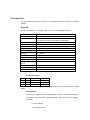
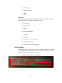
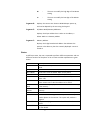
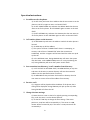
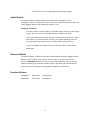
ARM VoIP Telephone
User’s Manual
Jianchi Chen
Electrical Engineering Department
California Institute of Technology
1
Contents
Overview ...........................................................................................................................................3
User Interface ....................................................................................................................................4
Keypad: ..........................................................................................................................................4
Keyboard layout: .........................................................................................................................4
Shift Mode: .................................................................................................................................5
Display Module: ..............................................................................................................................5
Segment A: .................................................................................................................................6
Segment B: .................................................................................................................................6
Segment C: .................................................................................................................................6
Segment D: .................................................................................................................................7
Segment E: .................................................................................................................................7
Segment F:..................................................................................................................................7
States: ............................................................................................................................................7
Operation Instructions: ...................................................................................................................8
1.
Set addresses for the phone: ................................................................................................8
2.
Call another phone on the internet: ......................................................................................8
3.
Save a number into directory/ recall a number from directory: ...............................................8
4.
Receive a call: ......................................................................................................................8
5.
Change the time settings: .....................................................................................................8
Audio Module ....................................................................................................................................9
Loopback Test Mode: ..................................................................................................................9
Ethernet Module ................................................................................................................................9
Revision History:.................................................................................................................................9
2
Overview
The Voice over IP (VoIP) telephone is a microprocessor-based system that allows the
user to make and receive phone calls over the internet. The system handles voice
quality audio signals (300Hz to 4 KHz). It makes connection to the internet via an
Ethernet cable, and communicates with the internet at the speed of 10 Mbit/s (1.25
MB/s). It is capable of making calls to any other VoIP phone that is using the same
communication protocol. The user may call another VoIP phone by dialing its IP address,
and the user may also save the address into contact directory. The system also displays
the current time, which allows the user to change its settings.
The system requires a 5V-12V power supply with a 5-pin DIN male power connector.
The user can power up the system by plugging the PS into the Power Connector.
The user will be able to use the following features:
•
•
Internet Setting
Call
-Set the IP, Subnet mask, Gateway for the phone
-Call the Address entered
•
•
•
•
Memory Save
Memory Recall
Receive Call
Set Clock
-Save the number in memory
-recall a number from memory
-Receive call from other phones and display caller’s IP
-Modify the clock time displayed on the screen
Power Connector
Reset Button
Speaker/Earplug jack
Microphone jack
Headphone Set
Link Indicator
Ethernet Jack
3
Display Module
Keypad
User Interface
The user interface of the VoIP consists of a 4*4 keypad and a 24*2-character LCD display
module.
Keypad:
The phone employs a 4*4 keypad, which consists of the following functions:
Key name
Number
Set IP
Set Subnet Mask
Set Gateway
Memory Save
Memory Recall
Send
Offhook
Onhook
Escape
Backspace
Move Set_time
Cursor
Set time
Shift
Restart
Description
0~9
Press to enter the IP address that is wished to be dialed.
Press again will return to the phone to IDLE state.
Press to enter Subnet Mask. Press again to return.
Press to enter Gateway. Press again to return.
Save the address to memory
Recall a saved address to memory
Dial the address entered
Go offhook
Go onhook
Go back to the Idle state.
Delete the last input.
Move the cursor to the left or right to set current time
Change the time setting.
Switch between Normal Mode and Shift Mode.
Restart the entire system.
Keyboard layout:
1
2
3
A
4
5
6
B
7
8
9
C
*
0
#
D
Key “D” is the SHIFT key. It is used for switching between the normal mode and the Shift
Mode.
Normal Mode:
The system is originally in Normal Mode when power up. Under Normal Mode,
the number keys are used for inputting numbers. The function key are mapped
as below:
A – Set IP Address.
B – Set Subnet Mask.
4
C – Set Gateway.
D – Go to Shift Mode.
‘*’ – Send.
‘#’ – Escape.
Shift Mode:
The system goes into Shift Mode after the SHIFT key is first pressed. Under Shift
Mode, the functions of the keys are mapped as below:
A – Memory Save.
B – Memory Recall.
C – Onhook.
D – Go to Normal Mode.
‘*’ – Offhook.
‘#’ – Backspace.
‘4’ – Set-time cursor move to the left.
‘5’ – Change time setting.
‘6’ – Set-time cursor move to the right.
Display Module:
The VoIP phone uses a Optrex 24*2 character LCD display module. It will display
the IP address/Subnet Mask/Gateway address, the memory address, the current
state of the entire system, and the current time.
The layout of the display is shown below:
A
B
C
5
D
E
Segment A:
F
Boot-up messages.
The system will display messages when the system performs
initialization and self-testing upon boot-up. Most of these
messages will only be present for a very short amount of time.
Messages that will be displayed:
“Display Ready!”
“Keypad Ready!”
“Codec Ready!”
“DRAM Test Done!”
“DRAM Failed!” – This message will only show up if the self
testing of the Dynamic Random Access Memory module has
encountered a failure. In that case, the user is suggested to
contact the designer.
Segment B:
State information.
The state information indicates the state that the system is
currently in, and also what the user is expected to do. Details
about the states will be further explained in the States section.
Segment C:
Set-time cursor position.
The cursor position indicates where the set-time cursor is
actually on. The user can move the cursor to the left or to the
left using the keypad. The information about the cursor position
indicator is listed below:
N
-
The user cannot change the time setting.
H
-
The user can modify the Hour setting.
6
M
-
The user can modify the high digit of the Minute
setting.
m
-
The user can modify the low digit of the Minute
setting.
Segment D:
Displays the current time. Reset to 00:00:00 upon power up,
and can be adjusted by the user using the keypad.
Segment E:
IP/Subnet Mask/Gateway Addresses.
Displays the 4-byte address that is either an IP address, a
Subnet Mask or a Gateway address.
Segment F:
Memory Address.
Displays the 2-digit hexadecimal address that indicates the
position in the directory that the currently-displayed contact is
stored at.
States:
At different states, the user is expected to perform different operations and use
different functions of the phone. A list of states and their explanations is given
below:
STATE NAME
IDLE STATE
SET IP
SET SUBNET
SET GATEWAY
ONHOOK
OFFHOOK
MEMORY
SAVE
MEMORY
RECALL
RECALLED
RINGING
CONNECTING
CONNECTED
State Explanation
Initial state of the system. Awaits user to select function and
mode.
Awaits user to set the IP address for the phone.
Awaits user to set the Subnet Mask for the phone.
Awaits user to set the Gateway for the phone.
Indicates that the system is not in use and is ready to receive
phone calls.
Indicates that the system is in use and is ready to call another
phone. Awaits user to dial the address to be called.
Save the currently-displayed IP address into contact directory
in the memory.
Recall the number from the specified position of the contact
directory.
A number has been recalled from the contact directory
Either the user is making a call or the phone is called by
another phone on the internet. The system will produce a
ringtone.
The phone is trying to connect to the address that the user
dialed.
The phone has established a connection with the address that
the user dialed.
7
Operation Instructions:
1. Set addresses for the phone:
a). Hit SET IP Key and enter the IP address that the user wants to set the
phone at. Hit SET IP again to return to the IDLE STATE.
b). Hit SET SUBNET MASK Key and enter the Subnet Mask that the user
wants to set for the phone. Hit SET SUBNET again to return to the IDLE
STATE.
c). Hit SET GATEWAY Key and enter the Gateway that the user wants to
set for the phone. Hit SET GATEWAY again to return to the IDLE STATE.
2. Call another phone on the internet:
a). Hit OFFHOOK Key and enter the address at which the other phone is
located.
b). Hit SEND Key to dial the address.
c). The system will show “CONNECTING” when it is attempting to
connect, and will show “CONNECTED” when the connection is
established, and thus a ringtone will be heard until the other user picks
up the call.
d). In the OFFHOOK state, hitting ONHOOK Key will return the system
into IDLE state. In the CONNECTING process or in any time during the
call, hitting SEND Key will return the system to IDLE STATE.
3. Save a number into directory/ recall a number from directory:
a). In SET IP STATE or OFFHOOK STATE, hit MEM SAVE Key at any time
and enter the location in contact directory will save the entered IP
address into the specified location of memory.
b). Hit MEM RECALL Key and enter the location in directory that the
user wants to access will recall the address from memory.
4. Receive a call:
a). A ringtone will be played and the IP address of the phone that is
calling will be displayed. Hitting SEND Key will pick up the call, while
hitting ESCAPE will refuse the call.
5. Change the time settings:
a). Move the time cursor to the left or right by pressing corresponding
keys, until the cursor is on the desired position.
b). Hit the SET TIME key to change the time setting. If the cursor
position is on H, hour will be increased by 1; if the cursor is on M,
minute will be increased by 10; if the cursor is on m, minute will be
increased by 1.
8
c). Move the time cursor to N to disable time-setting changes.
Audio Module
The system employs a COREL Headset that includes both a headphone and a
microphone. The user is allowed to replace it with other speaker/microphone devices by
simply plugging them into the speaker/microphone jacks.
Loopback Test Mode:
If the user wishes to test the quality of the audio devices without actually calling
anyone, the user may do so by using the built-in loopback test mode.
To enter the loopback test mode, the user will simply have to hit KEY “9” under
SHIFT Mode. The system will then act simply as an audio amplifier, which the
user may talk into and which the user may hear his/her own voice from.
To exit the loopback test mode, the user can simply hit KEY “9” under SHIFT
Mode again.
Ethernet Module
The system requires an Ethernet cable with a standard RJ45 connector plugged into the
Ethernet jack to connect to the internet. The Link Indicator (a yellow LED, see the
picture in OVERVIEW) will light up once a link has been established. The user can also
observe the blinking of the Activity Indicator (green LED on the right of the RJ45 jack)
once the system is sending and receiving data through/from the internet.
Revision History:
01/20/2013
Jianchi Chen
Initial Revision
04/04/2013
Jianchi Chen
Final Edition
9