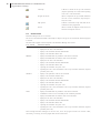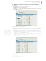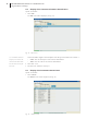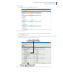
1
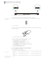
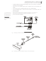
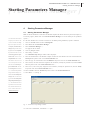
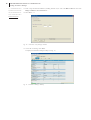
PARAMETERS MANAGER 2.10 - USER MANUAL
Summary
[ Parameters Manager ]
Summary
Important
Important .......................................................................................................................................................... 5
Introduction
Introduction ...................................................................................................................................................... 7
Connecting the instrument to the Personal Computer
2
Connecting the instrument to the Personal Computer ............................................................................... 9
2.1
Foreword ............................................................................................................................................................ 9
2.2
Connecting an instrument with TTL serial port to the Personal Computer ............................................ 9
2.2.1
Requisites ........................................................................................................................................................... 9
2.2.2
Connecting the instrument to the Personal Computer ............................................................................. 1 0
2.3
Connecting an instrument with RS-485 serial port to the Personal Computer ..................................... 1 1
2.3.1
Requisites ......................................................................................................................................................... 1 1
2.3.2
Connecting the instrument to the Personal Computer ............................................................................. 1 2
Installing Parameters Manager
3
Installing Parameters Manager ..................................................................................................................... 1 5
3.1
Foreword .......................................................................................................................................................... 1 5
3.2
Requisites ......................................................................................................................................................... 1 5
3.3
Installing Parameters Manager ..................................................................................................................... 1 5
3.4
Uninstalling Parameters Manager ................................................................................................................ 1 5
Starting Parameters Manager
4.1
Starting Parameters Manager ........................................................................................................................ 1 7
Using Parameters Manager
5
Using Parameters Manager ........................................................................................................................... 1 9
5.1
Foreword .......................................................................................................................................................... 1 9
5.2
Parameters Manager desktop ........................................................................................................................ 1 9
5.3
User account ................................................................................................................................................... 2 0
5.3.1
Access to the program ................................................................................................................................... 2 1
5.4
Display and modification the parameters value of the instrument .......................................................... 2 2
5.5
Modification of the level of accessibility of the instrument parameters ................................................ 2 3
5.6
Display and modification the machine states of the instrument ............................................................. 2 4
5.7
Display the I/O state of the instrument ...................................................................................................... 2 5
5.8
Display of the instrument firmware identification .................................................................................... 2 6
5.9
Display of the instrument alarms state ....................................................................................................... 2 6
5.10
Exporting the instrument set-up into a file ................................................................................................ 2 7
5.10.1 Foreword .......................................................................................................................................................... 2 7
5.10.2 Exporting the instrument set-up into a file ................................................................................................ 2 7
5.11
Importing into one or more instruments of the set-up of another instrument
(exported previously into a file) .................................................................................................................. 2 8
3
4
PARAMETERS MANAGER 2.10 - USER MANUAL
Summary
5.11.1 Foreword .......................................................................................................................................................... 2 8
5.11.2 Importing into an instrument of the set-up of another instrument (exported previously into a file) .... 2 8
5.11.3 Importing into several instruments of the set-up of another instrument (exported previously into a file) ... 3 1
Updating Parameters Manager
6
Updating Parameters Manager ..................................................................................................................... 3 3
6.1
Foreword .......................................................................................................................................................... 3 3
6.2
Checking availability of Parameters Manager updates .............................................................................. 3 3
PARAMETERS MANAGER 2.10 - USER MANUAL
Important
[ Parameters Manager ]
Important
Important
Read these instructions carefully before use and follow all recommendations; keep these instructions for future
reference.
The devices must be disposed of according to local Standards regarding the collection of electric and electronic
appliances.
5
PARAMETERS MANAGER 2.10 - USER MANUAL
Introduction
[ Parameters Manager ]
Introduction
Introduction
Parameters Manager is a program used with Evco instruments that have a serial port (TTL or RS-485) and that
support the MODBUS communication protocol (to obtain knowledge regarding Evco instruments compatible
with Parameters Manager, consult The list of instruments compatible with Parameters Manager; the document is
available on www.evco.it).
With Parameters Manager it is possible:
•
to display and modify the parameters value of the instrument
•
modify the level of accessibility of the instrument parameters
•
display and modify the machine states of the instrument
•
display the I/O state of the instrument
•
display the instrument firmware identification
•
display the state of the instrument alarms
•
export the instrument set-up in a file
•
import the set-up of another instrument into one or more instruments (exported previously into a file).
The access to these functions is subject to the type of user account with which the program is accessed.
Parameters Manager has the following user accounts:
•
USER (normally used by the final user)
•
SERVICE (normally used by staff in charge of technical support)
•
OEMUser (normally used by staff in charge of inspection of the appliance on which the instrument is
•
OEM (normally used by staff in charge of elaboration of instrument set-up).
installed)
The availability of the functions depends on the type of instrument) for further information, contact the
technical after-sales support at [email protected]).
If access to Internet is available, it is possible to check the immediate availability of Parameters Manager updates.
7
PARAMETERS MANAGER 2.10 - USER MANUAL
Connecting the instrument to the Personal Computer
[ Parameters Manager ]
Connecting the instrument to the Personal Computer
2
Connecting the instrument to the Personal Computer
2.1
Foreword
Parameters Manager is compatible with Evco instruments, which support the MODBUS communication protocol.
To obtain knowledge regarding Evco instruments compatible with Parameters Manager, consult The list of
instruments compatible with Parameters Manager (the document is available on www.evco.it).
If Parameters Manager is used with instruments that have the TTL serial port, see paragraph 2.2; if, however,
Parameters Manager is used with instruments that have the RS-485 serial port, see paragraph 2.3.
To be aware of the type of serial port, consult the instrument user instructions.
2.2
Connecting an instrument with TTL serial port to the Personal Computer
2.2.1
Requisites
Make sure you have:
•
instruments with TTL serial port
•
EVIF20TRX serial interface (to interface the instrument with the Personal Computer)
•
1256800042 telephone cable (to connect the EVIF20TRX serial interface to the Personal Computer)
•
1256800079 adapter (to adapt the 1256800042 telephone cable to the serial port of the Personal Computer).
The EVIF20TRX serial interface, the 1256800042 telephone cable and the 1256800079 adapter form the connecting kit EVPROG01 (see Fig. 1).
Fig. 1 - EVIF20TRX serial interface, 1256800042 telephone cable and 1256800079 adapter.
9
10
PARAMETERS MANAGER 2.10 - USER MANUAL
Connecting the instrument to the Personal Computer
Fig. 2 - Detail of the 1256800042 telephone cable.
Make sure that the Personal Computer has a free COM and does not use other programs.
(1)
if the COM has 25 pins, use a
The COM is a serial port with 9 pins, normally situated on the back of the Personal Computer (see Fig. 3)
(1)
.
9 pin/25 pin adapter
Fig. 3 - COM with 9 pins.
If the Personal Computer does not have COM but USB port, the 0810500011 adapter must be used (from USB to
RS-232 serial; see Fig. 4).
Fig. 4 - 0810500011 adapter (from USB to serial RS-232).
To find out the number of the corresponding COM, operate as indicated:
1. Click on the Start button and select Control panel.
The Control panel screen will be displayed.
2. Select Performances and maintenance and then System.
The System property screen will be displayed.
3. Click on the Hardware board and then on the Device manager button.
The Device manager screen will be displayed.
4. Expand the Ports (COM and LPT) item.
2.2.2
Connecting the instrument to the Personal Computer
Operate as indicated (see Fig. 5):
(2)
•
make sure that the instrument is not powered
•
connect one of the two Micromatch connectors of the EVIF20TRX serial interface to the serial port of the
instrument
use the connector that is easi-
est to connect
(2)
•
connect one end of the 1256800042 telephone cable to the telephone connector of the EVIF20TRX serial interface
•
connect the other end of the 1256800042 telephone cable to the 1256800079 adapter
•
connect the 1256800079 adapter to a COM on the Personal Computer (or to the 0810500011 adapter, from
USB to RS-232 serial)
PARAMETERS MANAGER 2.10 - USER MANUAL
Connecting the instrument to the Personal Computer
•
power the instrument; alternatively power the EVIF20TRX serial interface (from which the instrument receives sufficient
some instruments do not have
•
make sure that the instrument baud rate (normally the Lb parameter) is set at 9.600 baud
the parameter or these have another
•
make sure that the instrument parity (normally the LP parameter) is set at even
power supply to support programming operations) with the EVPS power supply unit
(3)
(3) (4)
(3) (4)
.
name; for further information contact the technical after-sales at
[email protected]
(4)
to modify the parameters
value, consult the instrument user
instructions
Fig. 5 - Connecting an instrument with TTL serial port to the Personal Computer.
2.3
Connecting an instrument with RS-485 serial port to the Personal Computer
2.3.1
Requisites
Make sure you have:
•
instruments with RS-485 serial port
•
EVIF21RS7I serial interface (to interface the instrument with the Personal Computer)
•
1256800042 telephone cable (to connect the EVIF21RS7I serial interface to the Personal Computer)
•
1256800079 adapter (to adapt the 1256800042 telephone cable to the serial port of the Personal Computer).
The 1256800042 telephone cable and the 1256800079 adapter are supplied with the EVIF21RS7I serial interface
(see Fig. 6).
Fig. 6 - EVIF21RS7I serial interface, 1256800042 telephone cable and 1256800079 adapter.
11
12
PARAMETERS MANAGER 2.10 - USER MANUAL
Connecting the instrument to the Personal Computer
Fig. 2 - Detail of the 1256800042 telephone cable.
Make sure that the Personal Computer has a free COM and does not use other programs.
(1)
if the COM has 25 pins, use a
The COM is a serial port with 9 pins, normally situated on the back of the Personal Computer (see Fig. 3)
(1)
.
9 pin/25 pin adapter
Fig. 3 - COM with 9 pins.
If the Personal Computer does not have COM but USB port, the 0810500011 adapter must be used (from USB to
RS-232 serial; see Fig. 4).
Fig. 4 - 0810500011 adapter (from USB to serial RS-232).
To find out the number of the corresponding COM, operate as indicated:
1. Click on the Start button and select Control panel.
The Control panel screen will be displayed.
2. Select Performances and maintenance and then System.
The System property screen will be displayed.
3. Click on the Hardware board and then on the Device manager button.
The Device manager screen will be displayed.
4. Expand the Ports (COM and LPT) item.
2.3.2
Connecting the instrument to the Personal Computer
Operate as indicated (see Fig. 7 and Fig. 8):
(5)
•
make sure that the instrument is not powered
•
connect clamp “ 11 ” of the EVIF21RS7I serial interface to the “ + ” clamp of the instrument RS-485 serial
port
use a twisted pair
•
connect clamp “ 13 ” of the EVIF21RS7I serial interface to the “ -- ” clamp of the instrument RS-485 serial
port
•
(6)
pair up the cable to that already
connected as much as possible
(5)
(5)
connect clamp “ 15 ” of the EVIF21RS7I serial interface to the “ S ” clamp of the instrument RS-485 serial
port
(6)
PARAMETERS MANAGER 2.10 - USER MANUAL
Connecting the instrument to the Personal Computer
•
to reduce the reflections on the signal transmitted through the cable, insert the termination of the EVIF21RS7I
•
connect one end of the 1256800042 telephone cable to the telephone connector of the EVIF21RS7I serial
•
connect the other end of the 1256800042 telephone cable to the 1256800079 adapter
•
connect the 1256800079 adapter to a COM on the Personal Computer (or to the 0810500011 adapter, from
serial interface and of the instrument
interface
USB to RS-232 serial)
•
power the instrument
some instruments do not have
•
make sure that the instrument baud rate (normally the Lb parameter) is set at 9.600 baud
the parameter or these have another
•
make sure that the instrument baud rate (normally the Lb parameter) is set at even
name; for further information con-
•
power the serial interface EVIF21RS7I.
(3)
tact the technical after-sales at
[email protected]
(4)
to modify the parameters
value, consult the instrument user
instructions.
Fig. 7 - Connecting an instrument with RS-485 serial port to EVIF21RS7I.
Fig. 8 - Connecting an instrument with RS-485 serial port to the Personal Computer.
(3) (4)
(3) (4)
13
PARAMETERS MANAGER 2.10 - USER MANUAL
Installing Parameters Manager
[ Parameters Manager ]
Installing Parameters Manager
3
Installing Parameters Manager
3.1
Foreword
In an old version of Parameters Manager is installed in the Personal Computer, before installing make a copy of
(7)
on the basis of the predefined
the folder containing the old version
(7)
.
setting, Parameters Manager is installed
in the C:\Evco\Ricsparamsmanager
3.2
Requisites
folder
Make sure that the Personal Computer has the following minimum system requisites:
•
Microsoft ® Windows XP or Microsoft® Windows Vista installed
•
800 MHz processor (recommended 1.2 GHz)
•
512 MB RAM
•
100 MB space available on the hard disk
•
SVGA monitor
•
CD-ROM unit
•
mouse or compatible pointing peripheral
•
serial port (COM or USB with 0810500011 adapter, from USB to RS-232 serial).
3.3
Installing Parameters Manager
Operate as indicated:
(8)
access the operational system
1. Start the operational system
(8)
.
with the administrator account of the
2. Close all applications, including antivirus programs.
Personal Computer
3. Insert the Parameters Manager CD into the CD-ROM unit.
(9)
The Languages dialogue window will be displayed
if the dialogue window is not
displayed, double click on the
(9)
.
4. Carry out the instructions displayed.
parameters_manager_setup.exe
The Settings dialogue window will be displayed:
file in the CD-ROM unit. If
•
if an old version of Parameters Manager is installed in the Personal Computer and you want to keep the
Microsoft® Vista is used, use the
configuration and/or log files, select the Keep previous configuration files if present check box and/
right key on the mouse to click on
or Keep previous data files if present.
the file and then select Run as ad-
5. Select Next >.
The Parameters Manager guided installation will be started.
ministrator from the quick choice
menu.
6. Carry out the instructions displayed.
3.4
Uninstalling Parameters Manager
Operate as indicated:
1. Click on the Start button and select All Programs.
2. Select Evco and then Parameters Manager.
3. Select Uninstall.
4. Select Next >.
The Parameters Manager guided uninstalling will be started.
5. Carry out the instructions displayed.
15
PARAMETERS MANAGER 2.10 - USER MANUAL
Starting Parameters Manager
[ Parameters Manager ]
Starting Parameters Manager
4
Starting Parameters Manager
4.1
Starting Parameters Manager
Make sure that the instrument is connected to the Personal Computer and that the devices are powered (see chapter 2).
To start the program, double click on the EVCO Parameters Manager icon on the desktop of the operational
(10) if Microsoft Vista is used, use
system
the right key on the mouse to click
If it has been decided not to create the connection on the desktop during installation, operate as indicated:
on the icon and then select Prop-
1. Click on the Start button and select All Programs.
erty from the quick choice menu.
2. Select Evco and then Parameters Manager.
The Property - EVCO Parameters
3. Select Parameters Manager
®
Manager dialogue window will be
(10)
.
4. Close any dialogue window.
ity board and then make sure that
5. Select Setup > Network.
ible Mode for check box of the
Compatible Mode unit is selected.
.
The program will be started.
displayed. Click on the Compatibil-
the Run the program in Compat-
(11)
The Connection setup dialogue window will be displayed.
6. Select the COM number of the Personal Computer to which the serial interface has been connected from the
Serial port drop-down menu of the Serial connection unit.
Select Windows XP (Service Pack
7. Select the type of serial interface from the Hardware drop down menu of the Serial connection unit.
2) from the drop-down menu and
8. Select 9600 (or the same baud rate assigned to the instrument, normally the parameter Lb) from the Baud
make sure that the Run this program as administrator check box
of the Privilege level unit is selected
rate drop down menu of the Serial connection menu
(3)
.
9. Select Even (or the same parity assigned to the instrument, normally the parameter LP) from the Parity
drop down menu of the Serial connection menu
(3)
.
(11) on the basis of the predefined
10. Select MODBUS from the Protocol drop-down menu of the Serial connection unit.
setting, Parameters Manager is in-
11. Select Next > > > (see Fig. 9).
stalled in the C:\Evco\Ricsparams
manager folder; the name of the
program file C:\Evco\Ricsparams
manager\Bin\paramsmanager.exe
(3)
some instruments do not have
the parameter or these have another
name; for further information contact the technical after-sales at
[email protected]
Fig. 9 - Connection setup dialogue window.
12. At the end of initialisation, select Next > > > again.
17
18
PARAMETERS MANAGER 2.10 - USER MANUAL
Starting Parameters Manager
(3)
some instruments do not have
the parameter or these have another
name; for further information con-
13. Enter a range of instrument addresses (normally parameter LA) to scan in the Min and Max text box of the
Range of addresses to be checked unit
(3)
.
14. Select Next > > >.
tact the technical after-sales at
[email protected].
Fig. 10 - Connection setup dialogue window.
15. At the end of scanning, select Close.
To display the Parameters Manager desktop (see Fig. 11).
Fig. 11 - Parameters Manager desktop.
PARAMETERS MANAGER 2.10 - USER MANUAL
Using Parameters Manager
[ Parameters Manager ]
Using Parameters Manager
5
Using Parameters Manager
5.1
Foreword
The availability of the functions described in this chapter depends on the type of instrument connected; for
further information, contact the technical after-sales support at [email protected].
5.2
Parameters Manager desktop
When Parameters Manager has been started, the desktop is displayed (see Fig. 12).
Fig. 12 - Parameters Manager desktop.
The table below supplies a brief description of the Parameters Manager desktop speed buttons:
Speed button
Name
Description
Network setup
It allows to modify the program settings relative
to the communication between the instrument and
the Personal Computer
Program setup
It allows to modify the program settings relative
to the instrument parameters display and importing in one or more instruments of the set-up of
another instrument (exported previously into a
file)
Parameters
Allows to display instrument parameters
Save
Allows to export the instrument set-up in a file
19
20
PARAMETERS MANAGER 2.10 - USER MANUAL
Using Parameters Manager
Load map
It allows to consult the set-up of an instrument
(exported previously into a file) before importing
it into one or more instruments
Program the device
Allows to import the set-up of another instrument
into one or more instruments (exported previously into a file)
Map preview
It allows to consult the set-up with which the in-
Search
Allows to search the displayed screen for the text
strument has been programmed
entered in the adjacent text box
5.3
User account
Parameters Manager has for user accounts.
The access to the functions described in this chapter is subject to the type of user account with which the program
is accessed.
The table below supplies a brief description of the Parameters Manager user account:
User account
Functions allowed
USER
•
display of the instrument machine states
•
display the I/O state of the instrument
•
display of the instrument firmware identification
SERVICE
•
display of the instrument alarms state
•
display and modification the parameters value of the instrument
•
display and modification the machine states of the instrument
•
display the I/O state of the instrument
•
display of the instrument firmware identification
•
display of the instrument alarms state
•
exporting the instrument set-up into a file
•
importing into one or more instruments of the set-up of another instrument (exported
previously into a file)
OEMUser
•
display of the parameters value of the instrument
•
display of the instrument machine states
•
display the I/O state of the instrument
•
display of the instrument firmware identification
•
display of the instrument alarms state
•
exporting the instrument set-up into a file
•
importing into one or more instruments of the set-up of another instrument (exported
•
display and modification the parameters value of the instrument
•
modification of the level of accessibility of the instrument parameters
•
display and modification the machine states of the instrument
•
display the I/O state of the instrument
•
display of the instrument firmware identification
•
display of the instrument alarms state
•
exporting the instrument set-up into a file
•
importing into one or more instruments of the set-up of another instrument (exported
previously into a file)
OEM
previously into a file)
When starting Parameters Manager for the first time, access the program with the user account USER;
successively, on start-up, access the program with the last account used.
PARAMETERS MANAGER 2.10 - USER MANUAL
Using Parameters Manager
5.3.1
Access to the program
Operate as indicated:
1. Select Setup > Log in.
The Password dialogue window will be displayed.
2. Select the type of user account from the drop-down menu (for example OEM) and enter the password of the
(12) make sure you do not use the
account into the text box (see Fig. 13)
letter "l" instead of number 1 and
The account passwords are stated on the Certificate of Authenticity.
(12)
.
the letter "o" instead of number 0
Fig. 13 - Password dialogue window.
3. Select Ok.
The Parameters screen will be displayed (see Fig. 14).
Fig. 14 - Parameters screen.
21
22
PARAMETERS MANAGER 2.10 - USER MANUAL
Using Parameters Manager
5.4
Display and modification the parameters value of the instrument
Operate as indicated:
(13) access the program with
1. Access the program with SERVICE, OEMUser or OEM user account (see paragraph 5.3.1)
(13)
.
OEMUser user account, the param-
The Parameters screen will be displayed (see Fig. 14).
eters value is only displayed
The parameters are found on several board; to put them in a unique board, click on the
(14) to show any parameters on the
The list that follows supplies a brief description of the data given in the Parameters screen columns
screen that were to be hidden, se-
•
Label: states the parameter code
lect Show > Hidden; to show any
•
Name: states the description of the parameter
parameters on the screen that due
•
Value: states the current value of the parameter
to the value of others are insignifi-
•
Map: it states the parameter value that is set with the reset procedure of the factory settings
cant, select Show > Inactive
•
Measure unit: states the unit of measurement of the parameter
(15) to show/hide the columns, use
•
Min: states the minimum value that can be attributed to the parameter
the right key on the mouse to click
•
Max: states the maximum value that can be attributed to the parameter
•
Visibility: states the level of accessibility of the parameter (see paragraph 5.5).
on the name of the column and then
select the column from the quick
choice menu
(16) on the basis of the predefined
2. Double click on the parameter value.
A text box or drop-down menu will be displayed.
3. Enter the value in the text box or select the value from the drop-down menu (see Fig. 15).
setting, the column is empty; to show
the value, use the right key on the
mouse to click on the parameter line
and then select Memo reference
value from the quick choice menu
(any differences between the value
stated in the Value column and that
reported in the Map column are
highlighted with another colour)
Fig. 15 - Parameters value modification screen.
4. Press Enter.
5. Select File > Exit.
6. Disconnect the instrument serial port.
(14)
.
(16)
(15)
:
PARAMETERS MANAGER 2.10 - USER MANUAL
Using Parameters Manager
5.5
Modification of the level of accessibility of the instrument parameters
Operate as indicated:
1. Access the program with OEM user account (see paragraph 5.3.1).
The Parameters screen will be displayed (see Fig. 14).
2. Use the right key on the mouse to click on the parameter line and then select a value from the quick choice
menu Visibility (see Fig. 16).
Fig. 16 - Parameters access level modification screen.
The list that follows supplies a brief description of the values from the drop-down menu Visibility (see
Fig. 17):
(14) to show any parameters on the
•
Hide: allows to hide the parameter (in this case the data given in the column Visibility is Hidden)
screen that were to be hidden, se-
•
Level1: allows to bring the parameter to the first level (usually not protected by access password; in this
case the data given in the column Visibility is FirstLevel)
lect Show > Hidden; to show any
parameters on the screen that due
•
Level2: allows to bring the parameter to the second level (usually protected by access password; in this
case the data given in the column Visibility is Password)
to the value of others are insignificant, select Show > Inactive
(14)
•
Level3: value protected.
Fig. 17 - Parameters access level screen.
3. Select File > Exit.
4. Disconnect the instrument serial port.
23
24
PARAMETERS MANAGER 2.10 - USER MANUAL
Using Parameters Manager
5.6
Display and modification the machine states of the instrument
Operate as indicated:
(17) access the program with
USER or OEMUser user account, the
1. Select Status
(17)
.
The Status screen will be displayed (see Fig. 18).
machine states can be displayed only
Fig. 18 - Status screen.
.
The machine states are positioned on several boards; to place them on one board, click on the board
(15) to show/hide the columns, use
The list that follows supplies a brief description of the data given in the Status screen columns
the right key on the mouse to click
•
Name: states the description of the machine state
on the name of the column and then
•
Value: states the current value of the machine state
select the column from the quick
•
Map: states the value of the machine state on the basis of factory setting
choice menu
•
Measure unit: states the unit of measurement of the machine status
(18) on the basis of the predefined
•
Min: states the minimum value that can be attributed to the machine state
setting, the column is empty; to show
•
Max: states the maximum value that can be attributed to the machine state.
the value, use the right key on the
2. Double click on the machine state value.
mouse to click on the machine state
A drop-down menu will be displayed.
line and then select Memo refer-
3. Select the value from the drop-down menu (see Fig. 19).
ence value from the quick choice
menu (any differences between the
value stated in the Value column and
that reported in the Map column are
highlighted with another colour)
Fig. 19 - Machine states value modification screen.
4. Press Enter.
5. Select File > Exit.
(18)
(15)
:
PARAMETERS MANAGER 2.10 - USER MANUAL
Using Parameters Manager
6. Disconnect the instrument serial port.
5.7
Display the I/O state of the instrument
Operate as indicated:
1. Select I/O.
The I/O screen will be displayed (see Fig. 20).
Fig. 20 - I/O screen.
(15) to show/hide the columns, use
The list that follows supplies a brief description of the data given in the I/O screen columns
the right key on the mouse to click
•
Name: states the description of the I/O
on the name of the column and then
•
Value: states the current value of the I/O
select the column from the quick
•
Map: states the value of the state on the basis of factory setting
•
Measure unit: states the unit of measurement of the I/O.
choice menu
2. Select File > Exit.
3. Disconnect the instrument serial port.
(18)
(15)
:
25
26
PARAMETERS MANAGER 2.10 - USER MANUAL
Using Parameters Manager
5.8
Display of the instrument firmware identification
Operate as indicated:
1. Select Info.
The Info screen will be displayed (see Fig. 21).
Fig. 21 - Info screen.
(15) to show/hide the columns, use
The list that follows supplies a brief description of the data given in the I/O screen columns
the right key on the mouse to click
•
Name: states the description of the firmware identification
•
Value: states the value of the firmware identification.
on the name of the column and then
select the column from the quick
2. Select File > Exit.
choice menu
3. Disconnect the instrument serial port.
5.9
Display of the instrument alarms state
Operate as indicated:
1. Select Alarms.
The Alarms screen will be displayed (see Fig. 22).
Fig. 22 - Alarms screen.
(15)
:
PARAMETERS MANAGER 2.10 - USER MANUAL
Using Parameters Manager
(15) to show/hide the columns, use
The list that follows supplies a brief description of the data given in the Alarms
the right key on the mouse to click
•
Label: states the alarm code
on the name of the column and then
•
Name: states the description of the alarm
•
Value: states the current state of the alarm.
select the column from the quick
choice menu
(15)
:
3. Select File > Exit.
4. Disconnect the instrument serial port.
5.10 Exporting the instrument set-up into a file
5.10.1 Foreword
Parameters Manager allows to export the set-up of one instrument into the following file formats:
•
TXT - Microsoft ® NotePad
•
HTML - Microsoft® Internet Explorer
•
DOC - Microsoft® Word
•
XLS - Microsoft® Excel
•
MAP - Format property of Evco.
Parameters Manager also allows to import the set-up of another instrument into one or more instruments
(exported previously into a file) on condition that these have been exported in MAP format and that the
(19) to display the instrument
firmware identification of the instruments coincides
(19)
.
firmware identification, select Info
5.10.2 Exporting the instrument set-up into a file
Operate as indicated:
1. Access the program with SERVICE, OEMUser or OEM user account (see 5.3.1).
The Parameters screen will be displayed (see Fig. 14).
2. Double click on the MAP - Map identifier parameter value.
A text box will be displayed.
3. Enter a new value, made up from the $ symbol followed by two numbers (for example $01) in the text box
(see Fig. 23).
4. Press Enter.
Fig. 23 - Modification of the value of the map identifier screen.
5. Operate as indicated in paragraphs 5.4 and 5.5.
6. Select File > Save.
The Save as dialogue window will be displayed.
7. Enter the name of the file in the File name text box (for example EVX214N7 - Set-up LT cabinets) and
select the file format from the Save as drop-down menu (see Fig. 24).
27
28
PARAMETERS MANAGER 2.10 - USER MANUAL
Using Parameters Manager
Fig. 24 - Save as dialogue window.
8. Select Save.
9. Select File > Exit.
10. Disconnect the instrument serial port.
5.11
Importing into one or more instruments of the set-up of another instrument
(exported previously into a file)
5.11.1 Foreword
Parameters Manager allows to import the set-up of another instrument into one or more instruments (exported
previously into a file) on condition that these have been exported in MAP format and that the firmware
(19) to display the instrument
identification of the instruments coincides
(19)
.
firmware identification, select Info
5.11.2 Importing into an instrument of the set-up of another instrument (exported previously
into a file)
Operate as indicated:
1. Access the program with SERVICE, OEMUser or OEM user account (see paragraph 5.3.1).
The Parameters screen will be displayed (see Fig. 14).
2. Select File > Load map.
The Open dialogue window will be displayed.
3. Enter the pathway and name of the set-up file in the File name text box (for example EVX214N7 - Set-up
LT cabinets; see Fig. 25).
Fig. 25 - Open dialogue window.
PARAMETERS MANAGER 2.10 - USER MANUAL
Using Parameters Manager
4. Select Open.
The Loaded map screen will be displayed (see Fig. 26).
Fig. 26 - Loaded map screen.
The Loaded map screen allows to consult the set-up before importing it into the instrument.
5. Close the Loaded map screen.
The Parameters screen will be displayed again (any differences between the original set-up and that of
destination are highlighted in another colour; see Fig. 27).
Fig. 27 - Parameters screen: difference between the original set-up and the destination set-up.
29
30
PARAMETERS MANAGER 2.10 - USER MANUAL
Using Parameters Manager
(20) to disable the item and the
6. Select Device > Program
(20)
.
speed button, select Setup > Pro-
The Program parameters screen will be displayed.
gram.
If a set-up has been consulted, the Choose the map file text box states the pathway and the name of the set-
The Setup dialogue window will be
up file (see Fig. 28).
displayed.
Click on the Programming Settings
board and then unselect the Enable
check box
Fig. 28 - Program parameters screen.
7. Select Next.
Instrument programming will be started.
8. At the end of programing, select Next.
The Program parameters screen will be displayed again (see Fig. 28).
9. Select End.
The Parameters programming report screen will be displayed (see Fig. 29).
Fig. 29 - Parameters programming report screen.
10. Select End.
The Parameters screen will be displayed again (see Fig. 14).
11. Select File > Exit.
12. Disconnect the instrument serial port.
PARAMETERS MANAGER 2.10 - USER MANUAL
Using Parameters Manager
5.11.3 Importing into several instruments of the set-up of another instrument (exported previously into a file)
Operate as indicated:
1. Access the program with SERVICE, OEMUser or OEM user account (see paragraph 5.3.1).
The Parameters screen will be displayed (see Fig. 14).
2. Select File > Load map.
The Open dialogue window will be displayed.
3. Enter the pathway and name of the set-up file in the File name text box (for example EVX214N7 - Set-up
LT cabinets; see Fig. 25).
4. Select Open.
The Loaded map screen will be displayed (see Fig. 26).
The Loaded map screen allows to consult the set-up before importing it into the instrument.
5. Close the Loaded map screen.
The Parameters screen will be displayed again (any differences between the original set-up and that of
destination are highlighted in another colour; see Fig. 27).
6. Select Setup > Program.
The Setup dialogue window will be displayed.
7. Click on the Programming Settings board and then select the Automatic mode check box (see Fig. 30).
Fig. 30 - Setup dialogue window: Programming Settings board.
8. Select Apply.
(20) to disable the item and the
9. Select Device > Program
(20)
.
speed button, select Setup > Pro-
The Program parameters screen will be displayed.
gram.
If a set-up has been consulted, the Choose the map file text box states the pathway and the name of the set-
The Setup dialogue window will be
displayed.
Click on the Programming Settings
board and then unselect the Enable
check box.
up file (see Fig. 28).
8. Select Next.
Instrument programming will be started.
31
32
PARAMETERS MANAGER 2.10 - USER MANUAL
Using Parameters Manager
9. At the end of programing, select Next.
The Program parameters screen will be displayed again (see Fig. 31).
Fig. 31 - Program parameters screen.
10. Disconnect the instrument serial port.
11. Connect the serial port of another instrument.
Instrument programming will be started.
12. Repeat points 10 and 11.
13. At the end of programing, select End.
The Parameters programming report screen will be displayed (see Fig. 32).
Fig. 32 - Parameters programming report screen.
14. Select End.
The Parameters screen will be displayed again (see Fig. 14).
15. Select File > Exit.
16. Disconnect the instrument serial port.
PARAMETERS MANAGER 2.10 - USER MANUAL
Updating Parameters Manager
[ Parameters Manager ]
Updating Parameters Manager
6
Updating Parameters Manager
6.1
Foreword
If access to Internet is available, it is possible to check the immediate availability of Parameters Manager updates.
Before installing the Parameters Manager update, make a copy of the folder containing the old version.
6.2
Checking availability of Parameters Manager updates
Operate as indicated:
1. Select Help > Check for upgrades.
The predefined browser will be started.
33
Parameters Manager 2.10 User manual for Windows®.
Version 1.00 August 2009.
Code 144PARM2100E00.pdf.
PT.
This publication is exclusive property of Evco, which prohibits reproduction and distribution,, unless expressly authorised by Evco itself. Evco does not assume any liability regarding the features,
technical data and possible errors in this document or deriving from use of the same. Evco cannot be held responsible for any damage caused by the failure to comply with the warnings. Evco reserves
the right to make any modifications at any time without jeopardising the essential functionality and safety features, without forewarning.