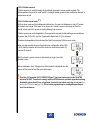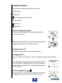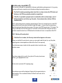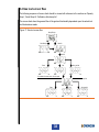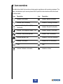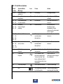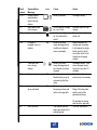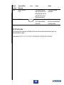
1
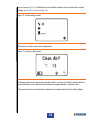
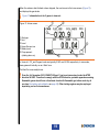
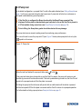
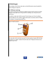
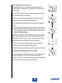
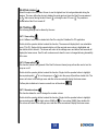
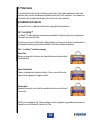
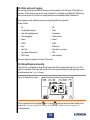
H2S
CO
CH4
Gas-Pro
User & Operator Manual
Gas-Pro
Multi-gas monitor
M07995/Eng
Issue 6 November 2013
NAVIGATION INSTRUCTIONS
The symbols in the left-hand margin of each page of the manual will enable you to carry out the
following functions:
Contents
Click on this button to display the Contents page.
Click on this button to display the previous page.
Click on this button to display the next page.
Click on this button to display the previous view (use it to return from a reference jump).
Click on this button to display next view (use it to return to a reference jump).
Exit
!
Click this button to exit the User and Operator Manual.
Press the Esc key to display normal Acrobat© Controls.
CONTENTS
PROLOGUE . . . . . . . . . . . . . . . . . . . . . . . . . . . . . . . . . . . . . . . . . . . . . 7
Gas-Pro Overview . . . . . . . . . . . . . . . . . . . . . . . . . . . . . . . . . . . . . . . . . . . . . . .7
Safety Information . . . . . . . . . . . . . . . . . . . . . . . . . . . . . . . . . . . . . . . . 8
Unpacking . . . . . . . . . . . . . . . . . . . . . . . . . . . . . . . . . . . . . . . . . . . . . 11
1. Set-up . . . . . . . . . . . . . . . . . . . . . . . . . . . . . . . . . . . . . . . . . . . . . . 12
1.1 Prior to use. . . . . . . . . . . . . . . . . . . . . . . . . . . . . . . . . . . . . . . . . . . . . . . . .12
1.2 Gas-Pro orientation . . . . . . . . . . . . . . . . . . . . . . . . . . . . . . . . . . . . . . . . . .12
1.3 Charging . . . . . . . . . . . . . . . . . . . . . . . . . . . . . . . . . . . . . . . . . . . . . . . . . . .13
. . . . . . . . . . . . . . . . . . . . . . . . . . . . . . . . . . . . . . . . . . .14
1.5 Quick view . . . . . . . . . . . . . . . . . . . . . . . . . . . . . . . . . . . . . . . . . . . . . . . . .15
2. Operation . . . . . . . . . . . . . . . . . . . . . . . . . . . . . . . . . . . . . . . . . . . 16
2.1 General . . . . . . . . . . . . . . . . . . . . . . . . . . . . . . . . . . . . . . . . . . . . . . . . . . . .16
2.2 Turn on . . . . . . . . . . . . . . . . . . . . . . . . . . . . . . . . . . . . . . . . . . . . . . . . . . . .16
2.3 Pump test . . . . . . . . . . . . . . . . . . . . . . . . . . . . . . . . . . . . . . . . . . . . . . . . . .20
2.4 Detecting gas . . . . . . . . . . . . . . . . . . . . . . . . . . . . . . . . . . . . . . . . . . . . . . .21
2.4.1 Diffusion monitoring . . . . . . . . . . . . . . . . . . . . . . . . . . . . . . . . . . . . .21
2.4.2 Pumped mode . . . . . . . . . . . . . . . . . . . . . . . . . . . . . . . . . . . . . . . . . .22
2.4.3 Manual sampling . . . . . . . . . . . . . . . . . . . . . . . . . . . . . . . . . . . . . . . .23
2.4.3.1 Using the Hand Aspirator . . . . . . . . . . . . . . . . . . . . . . . . . . . . .23
2.5 Alarms. . . . . . . . . . . . . . . . . . . . . . . . . . . . . . . . . . . . . . . . . . . . . . . . . . . . .24
2.5.1 Low battery alarm . . . . . . . . . . . . . . . . . . . . . . . . . . . . . . . . . . . . . . .24
2.5.2 Instantaneous alarm . . . . . . . . . . . . . . . . . . . . . . . . . . . . . . . . . . . . .24
2.5.3 Time weighted average alarm (TWA) . . . . . . . . . . . . . . . . . . . . . . . .24
2.5.4 Accepting and clearing alarms . . . . . . . . . . . . . . . . . . . . . . . . . . . .25
3
2.5.5 Sensor types . . . . . . . . . . . . . . . . . . . . . . . . . . . . . . . . . . . . . . . . . . .25
2.5.5.1 Oxygen sensors . . . . . . . . . . . . . . . . . . . . . . . . . . . . . . . . . . . .25
2.5.5.2 Electro-chemical sensors . . . . . . . . . . . . . . . . . . . . . . . . . . . . .25
2.5.5.3 Infra red sensors . . . . . . . . . . . . . . . . . . . . . . . . . . . . . . . . . . .25
2.5.5.4 Pellistor sensors. . . . . . . . . . . . . . . . . . . . . . . . . . . . . . . . . . . .26
2.5.5.5 Pellistor saver mode
. . . . . . . . . . . . . . . . . . . . . . . . . . . . .26
2.5.5.6 PID . . . . . . . . . . . . . . . . . . . . . . . . . . . . . . . . . . . . . . . . . . . . .27
2.6 Gas-Pro functions . . . . . . . . . . . . . . . . . . . . . . . . . . . . . . . . . . . . . . . . . . .28
2.6.1 Accessing the user menus . . . . . . . . . . . . . . . . . . . . . . . . . . . . . . . .28
2.6.2 Home screen
. . . . . . . . . . . . . . . . . . . . . . . . . . . . . . . . . . . . . . . .28
2.6.3 Manual zero
. . . . . . . . . . . . . . . . . . . . . . . . . . . . . . . . . . . . . . . . .28
2.6.4 Time weighted average
. . . . . . . . . . . . . . . . . . . . . . . . . . . . . . . .28
2.6.5 Pre-entry check (PEC)
. . . . . . . . . . . . . . . . . . . . . . . . . . . . . . . . .29
2.6.5.1 Starting a Pre-entry check . . . . . . . . . . . . . . . . . . . . . . . . . . . .29
2.6.5.2 Carrying out a Pre-entry check . . . . . . . . . . . . . . . . . . . . . . . .30
2.6.6 Peak review
. . . . . . . . . . . . . . . . . . . . . . . . . . . . . . . . . . . . . . . . .31
2.6.7 Settings
. . . . . . . . . . . . . . . . . . . . . . . . . . . . . . . . . . . . . . . . . . . .31
2.6.7.1 User setting
. . . . . . . . . . . . . . . . . . . . . . . . . . . . . . . . . . . .31
2.6.7.2 Pump setting
. . . . . . . . . . . . . . . . . . . . . . . . . . . . . . . . . . .31
2.6.7.3 Sounder volume
. . . . . . . . . . . . . . . . . . . . . . . . . . . . . . . . .31
2.7 Shut down . . . . . . . . . . . . . . . . . . . . . . . . . . . . . . . . . . . . . . . . . . . . . . . . .32
2.8 Additional Features . . . . . . . . . . . . . . . . . . . . . . . . . . . . . . . . . . . . . . . . . .32
2.8.1 +ve Safety™ . . . . . . . . . . . . . . . . . . . . . . . . . . . . . . . . . . . . . . . . . . . .32
2.8.1.1 +ve Safety™ indicator meanings . . . . . . . . . . . . . . . . . . . . . . .32
2.8.2 Data and event logging . . . . . . . . . . . . . . . . . . . . . . . . . . . . . . . . . . .33
2.8.3 Bump/Pump functionality . . . . . . . . . . . . . . . . . . . . . . . . . . . . . . . . .33
4
3. Gas testing and calibration . . . . . . . . . . . . . . . . . . . . . . . . . . . . . 34
3.1 Introduction . . . . . . . . . . . . . . . . . . . . . . . . . . . . . . . . . . . . . . . . . . . . . . . .34
3.2 Bump Test Functionality . . . . . . . . . . . . . . . . . . . . . . . . . . . . . . . . . . . . . .35
3.2.1 Speedy bump . . . . . . . . . . . . . . . . . . . . . . . . . . . . . . . . . . . . . . . . . . .36
3.2.1.1 Procedure . . . . . . . . . . . . . . . . . . . . . . . . . . . . . . . . . . . . . . . .36
3.2.2 Smart bump . . . . . . . . . . . . . . . . . . . . . . . . . . . . . . . . . . . . . . . . . . . .36
3.2.2.1 Procedure . . . . . . . . . . . . . . . . . . . . . . . . . . . . . . . . . . . . . . . .36
3.2.3 Calibration after bump fail . . . . . . . . . . . . . . . . . . . . . . . . . . . . . . . .37
3.2.3.1 Procedure . . . . . . . . . . . . . . . . . . . . . . . . . . . . . . . . . . . . . . . .37
3.3 New sensor calibration/service . . . . . . . . . . . . . . . . . . . . . . . . . . . . . . . .37
. . . . . . . . . . . . . . . . . . . . . . . . . . . . . . . . . . . . . . . . .38
4. Icon overview . . . . . . . . . . . . . . . . . . . . . . . . . . . . . . . . . . . . . . . . 39
5. Service and maintenance . . . . . . . . . . . . . . . . . . . . . . . . . . . . . . 40
6. PC interface and Portables-Pro . . . . . . . . . . . . . . . . . . . . . . . . . 41
6.1 General . . . . . . . . . . . . . . . . . . . . . . . . . . . . . . . . . . . . . . . . . . . . . . . . . . . .41
6.2 PC interface cable . . . . . . . . . . . . . . . . . . . . . . . . . . . . . . . . . . . . . . . . . . .41
7. Accessories . . . . . . . . . . . . . . . . . . . . . . . . . . . . . . . . . . . . . . . . . 42
. . . . . . . . . . . . . . . . . . . . . . . . . . . . . . . . . . . . . . . . . 44
9. Troubleshooting . . . . . . . . . . . . . . . . . . . . . . . . . . . . . . . . . . . . . . 45
9.1 Pump test failure . . . . . . . . . . . . . . . . . . . . . . . . . . . . . . . . . . . . . . . . . . . .45
9.2 Fault screens . . . . . . . . . . . . . . . . . . . . . . . . . . . . . . . . . . . . . . . . . . . . . . .45
9.2.1 Fault Descriptions . . . . . . . . . . . . . . . . . . . . . . . . . . . . . . . . . . . . . . .46
9.2.2 Fault codes . . . . . . . . . . . . . . . . . . . . . . . . . . . . . . . . . . . . . . . . . . . .48
5
10.Appendices . . . . . . . . . . . . . . . . . . . . . . . . . . . . . . . . . . . . . . . . . . 49
10.1 Sensors . . . . . . . . . . . . . . . . . . . . . . . . . . . . . . . . . . . . . . . . . . . . . . . . . .49
10.1.1 Toxic . . . . . . . . . . . . . . . . . . . . . . . . . . . . . . . . . . . . . . . . . . . . . . . . .49
10.1.2 Flammable Sensors . . . . . . . . . . . . . . . . . . . . . . . . . . . . . . . . . . . .50
10.1.3 Oxygen . . . . . . . . . . . . . . . . . . . . . . . . . . . . . . . . . . . . . . . . . . . . . . .50
10.1.4 IR . . . . . . . . . . . . . . . . . . . . . . . . . . . . . . . . . . . . . . . . . . . . . . . . . . . .50
10.1.5 PID . . . . . . . . . . . . . . . . . . . . . . . . . . . . . . . . . . . . . . . . . . . . . . . . . .50
10.2 Sensor Limitations . . . . . . . . . . . . . . . . . . . . . . . . . . . . . . . . . . . . . . . . .51
10.3 Charging and run times . . . . . . . . . . . . . . . . . . . . . . . . . . . . . . . . . . . . .52
10.4 Crowcon contacts . . . . . . . . . . . . . . . . . . . . . . . . . . . . . . . . . . . . . . . . . .53
Warranty . . . . . . . . . . . . . . . . . . . . . . . . . . . . . . . . . . . . . . . . . . . . . . . 54
6
PROLOGUE
Gas-Pro Overview
Thank you for purchasing the new Gas-Pro. At Crowcon we recognise the need for reliable and
robust personal monitors which are sized to be worn and simple to use.
Gas-Pro is a portable monitor capable of detecting up to 5 gases in a compact and wearable design
application focused solutions giving greater operating time and reduced set up time.
single button solution makes using and training quick and easy.
7
Safety Information
•
this manual. Gas-Pro must be operated within the limitations stated.
•
Read and understand all instructions in the operation section of this manual prior to use.
•
damaged in any way.
•
for repair/replacement.
•
Do not disassemble or substitute components as this may impair intrinsic safety and invalidate
•
Only genuine Crowcon replacement parts must be used; substitute components may
Maintenance” section for details.
•
No live maintenance is permissible.
•
Observe all warnings and instructions marked on the unit and within this manual.
•
Observe site health and safety procedures for gases being monitored and evacuation procedures.
•
Understand the screen display and alarm warnings prior to use.
•
•
the manual and only by trained personnel.
•
The Gas-Pro re-chargeable battery must only be charged in non-hazardous (safe) areas.
•
Only connect to Gas-Pro in a safe area for charging or communications.
•
greater than +40°C.
•
•
•
The devices are intended for use in normal atmospheric conditions of temperature –20 °C to
typically 21 % v/v (volume/volume).
8
•
•
•
•
Applicable Standards
IECEx
IEC 60079-0:2004 4th Edition
Electrical apparatus for explosive gas atmospheres Part 0: General requirements
IEC 60079-0:2007 5th Edition
Explosive atmospheres – Part 0: Equipment - General requirements
IEC 60079-1:2007 6th Edition
IEC 60079-11:2006 5th Edition
Ex d ia IIC T4 Gb Tamb -20°C to +55°C
9
ATEX:
EN 60079-0:2006
Electrical apparatus for explosive gas atmospheres Part 0: General requirements
EN 60079-0:2009
Explosive atmospheres – Part 0: Equipment - General requirements
EN 60079-1:2007
EN 60079-11:2007
II 2 G Ex d ia IIC T4 Gb Tamb -20°C to +55°C
UL
intrinsic safety.
10
Unpacking
Remove the Gas-Pro from the packaging. The standard accessories are under the supporting trays.
The following items will be included as standard:
Box contents
•
Gas-Pro
•
Quick Start Guide
•
CD Manual
•
Calibration report
The following items are optional:
Optional items
•
Charger cradle
•
Charger lead (see Power & Communication Cables Technical Data)
•
Flow plate (standard for pumped units)
i
i
i
i
i
If you have ordered a charger and/or cradle this will also be included in the box.
Further accessories are available but will not be contained in the box (see Section 7).
Should the unit be deep discharged, the charging indication will not be shown until the
unit has been charging for 1 hour and the operator button has been pressed.
When on and charging a warning will advise the user to turn the Gas-Pro off after 12
hours or remove from charge.
Store the battery in a full state and recharge at least once every 3 months.
11
1. Set-up
1.1 Prior to use
attain the full operating time (see Charging on page 13).
i
page 52.
The actual operating time will depend on the types of sensor installed.
1.2 Gas-Pro orientation
Figure 1: Gas-Pro
D-ring
Alarm bars
+ve Safety™ indicator
Sounder
Operator button
Pump inlet/outlet*
Sensor apertures
Alligator clip
* Blanked for non-pumped unit.
12
Charging cable
1.3 Charging
the charging socket
i
into
on the Gas-Pro and turn on the mains supply (see Figure 2 below). If a charging
The charger must be able to supply 6.5V@ 450mA with an output voltage that does not
exceed 9.1V (Um).
Figure 2: Charger connection
to green once fully charged. This state will continue until the trickle charge is complete. Charging will then
charged
(see Figure 3 below).
Figure 3: Charging indications
13
1.4
process (see Pump test on page 20).
pump and a non-magnetic version for PC calibration or for manual sampling. Although there is no
Figure 4). The pumped
symbol in the top left corner to aid recognition.
Figure 4:
PC Cal/Test Flow Plate
Figure 5 and tighten the securing screw
Figure 5:
14
.
1.5 Quick view
Figure 6 below will be displayed for 10 seconds.
Figure 6:
Gas type and unit detected
Battery status
Quickview icon
ID or serial number
i
The +ve Safety™ LED status is also shown (see Figure 1).
15
2. Operation
2.1 General
!
Before turning the Gas-Pro on, ensure it is in ‘clean air’ (i.e. outside, in normal air, away
from any plant process or suspected gas location). This will allow the Gas-Pro to be
zeroed using clean air as the base point. If the Gas-Pro is zeroed in contaminated air a
false gas reading can result, or the zero could fail.
2.2 Turn on
Firstly a test screen pattern will be generated. Watch this to ensure there are no missing pixels on
your display screen.
Figure 7:
the Gas-Pro is healthy.
i
i
i
automatically at this point (for more details on this, see Pump test on page 20).
If the battery level is low, an alarm will sound, and the battery icon on the screen will be partial.
the turn on sequence.
16
on page 34).
Figure 8: Gas test due screen
The next screen indicates when the Gas-Pro was last calibrated. It also indicates when the next calibration
is due with a warning symbol
Figure 9:
If the calibration due lockout feature has been enabled the lockout icon
Gas-Pro will not proceed past this point.
17
will be displayed and the
The next screen (Figure 10) will display the current detector settings (for more information on these
Gas-Pro functions on page 28).
Figure 10: Current settings screen
Figure 11:
An Autozero should not be performed unless the Gas-Pro is in clean air. Press the operator button to
If the operator button is not pressed the countdown will complete and this function will be skipped.
18
Figure 12)
and displays the gas levels.
i
Figure 12 shown below is for 5 gases in clean air.
Figure 12: Home screen
Gas type
Unit
Home Screen icon
Battery level
Pump present
(rotating when on)
2
The Gas-Pro is now ready for use.
!
From the 1st November 2010, EN60079-29 part 1 has been harmonised under the ATEX
directive 94/9/EC. Therefore to comply with the ATEX directive, portable apparatus sensing
use (see
on page 34). Other testing regimes may be employed
depending on local circumstances.
19
2.3 Pump test
on
page 12) will run a pump test during the start up process. A pump test will also be run whenever a
i
i
a Q-Test module during normal use (see
on page 33).
The pump test ensures accurate sealing as well as monitoring pump performance.
The user will need to cover the pump inlet
symbol on the screen.
(see Figure 13 below) when prompted to do so by the
Figure 13:
or fail
.
On failing the pump test the fail screen will persist with an audible alert until the button is pressed
For further detail on failing a pump test see
on page 45.
20
2.4 Detecting gas
water travelling up the sample line.
2.4.1 Diffusion monitoring
clipping the strong alligator clip to clothing/overalls in the breathing zone or through the use of a
chest harness.
icon.
Figure 14: Gas-Pro indicators
will also be red and
highlight the gas in alarm.
21
2.4.2 Pumped mode
on page 33). Gas-Pro can either be worn or used with hoses and probes to
sample from spaces prior to entry. The pump capacity in the Gas-Pro is 0.5l/m and will draw a sample of
gas from 30m within 80 seconds. Please note the expected losses for some gases below. Please allow at
least 3 seconds per meter of hose used.
Tube Type
Tube length
Measurement
CO (250ppm)
H2S (25ppm)
CH4
CO2
O2
i
Standard (AC0201/03/05/10/20/30)
5 metres
Gas Name
Carbon Monoxide
Hydrogen Sulphide
Methane
Carbon Dioxide
Oxygen
0ppm
0ppm
10 metres
Time
9s
10 s
10 s
9s
9s
0ppm
1ppm
30 metres
Time
20 s
20 s
20 s
20 s
20 s
1ppm
6ppm
Time
79 s
78 s
78 s
79 s
79 s
If Gas-Pro is operated in pumped mode in combination with an exhaust pipe, a set of
maximum tube).
i
Section 2.6.5 on page 29).
22
2.4.3 Manual sampling
If the internal pump option has not been chosen the hand aspirator may be used for pre-entry checks
and remote sampling. This is not however recommended for sample hoses longer than 5 meters
due to the amount of time (and therefore squeezes) it would take to get a repeatable sample to the
2.4.3.1 Using the Hand Aspirator
and the user should accept this. The bulb
achieved. The detector will at this point likely go into alarm (this is due to the pressure effect on
the oxygen sensor) and the bulb of the aspirator should not return to the rounded shape. If this
O2 sensor to stabilise to 20.9% and then attach the required sample hose length to the inlet on the
approximately 25cm up the tube. Therefore to sample from a 5 meter hose – at least 20 aspirations
expected during this process due to the extra pressure placed on the sensor (ie if the sample being
tested is 30ppm – the expected result onscreen will show 32ppm.
pumped option to reduce time and potential for error.
i
23
2.5 Alarms
The Gas-Pro has the following types of alarm:
•
•
•
Instantaneous
Time weighted average (TWA)
2.5.1 Low battery alarm
battery has at least 20 minutes of battery life remaining. After 20 minutes the Gas-Pro will enter full
!
power off without further warning unless charged.
2.5.2 Instantaneous alarm
other gases the Gas-Pro will go into alarm state 1 or 2 according to which level has been exceeded.
or
to indicate which level
2.5.3 Time weighted average alarm (TWA)
information about gas levels detected. If the average levels detected over a period of time exceeds
. The
!
i
TWA alarms cannot be cleared. (The 8 hour TWA can be reviewed in the user menu - see
Section 2.6.4 on page 28). The TWA can only be cleared by turning the Gas-Pro off (see
on page 32). Refer to Health and Safety guidelines on TWA alarms.
cleared by downloading the datalog via Portables-Pro.
24
2.5.4 Accepting and clearing alarms
Setting
Non-latched
i
Alarm 1
Alarms will not be latched returning
to non-alarm state without user
acceptance
Alarm 2
Alarm can be turned off only when gas
has returned to acceptable levels
Allows the user to silence alerts but
remains in alarm. Once gas has
returned to acceptable levels the user
needs to accept the state.
Alarm can be turned off only when gas
has returned to acceptable levels
Alarm can be turned off only when gas
has returned to acceptable levels
Alarm can be turned off only when gas
has returned to acceptable levels
While in alarm, the Gas-Pro will continue to record levels of all the gases being monitored.
2.5.5 Sensor types
•
Oxygen
•
Electro-chemical
•
Infra red (IR)
•
Pellistor
•
Photoionization Detector (PID)
2.5.5.1 Oxygen sensors
These sensors are in the form of an electro-galvanic fuel cell which is an electrical device used to
measure the concentration of oxygen gas in the ambient air. Set as default with both higher and
lower alarm levels.
2.5.5.2 Electro-chemical sensors
Electrochemical gas sensors measure the volume of a target gas by oxidising or reducing the target
gas at an electrode and measuring the resulting current.
2.5.5.3 Infra red sensors
25
2.5.5.4 Pellistor sensors
the presence of gas.
2.5.5.5 Pellistor saver mode
will indicate over range. If the alarm is so severe as to cause a sensor over-range the Gas-Pro
should have a gas test to ensure no lasting damage has occurred.
2
S or silicones.
To reduce the degradation the instrument the Gas-Pro employs a Pellistor saver mode.
– 95%) then the detector will turn off the sensor for a minimum period of 3
minutes 20 seconds.
After this time the sensor can be re-activated by a single click of the
operator button.
sensor will be turned off and the cycle starts again.
!
From the 1st November 2010, EN60079-29 part 1 has been harmonised under the ATEX
directive 94/9/EC. Therefore to comply with the ATEX directive, portable apparatus sensing
Gas
on page 34). Other testing regimes may be employed depending on
local circumstances.
26
2.5.5.6 PID
Isobutylene by changing the correction factor in the PID sensor type options
ensure correct performance in normal use.
The sensor may need maintenance if any of the following occur:
•
The baseline is climbing after zeroing the sensor
•
The sensor becomes sensitive to humidity
•
The baseline is unstable or shifts when the sensor is moved
•
Sensitivity of the sensor has dropped
Please refer to Crowcon application note PID-AN-001 for further details on maintenance and
cleaning of the PID sensor.
27
2.6 Gas-Pro functions
The following can be selected from the Gas-Pro user menu:
Home screen
Manual zero
Time weighted average (TWA) review
Pre-entry check
Peak review
Settings menu
2.6.1 Accessing the user menus
access the function menus.
Single click the operator button to scroll right until the required menu icon
is highlighted and then double click to select the function.
2.6.2 Home screen
2.6.3 Manual zero
time.
Certain operations will only take place if the Gas-Pro has been recently
calibration after failing a gas test if the unit has been manually zeroed in
the last 15 minutes.
2.6.4 Time weighted average
This function allows the 8 hour TWA to be reviewed. For more details on
on page 24.
28
2.6.5 Pre-entry check (PEC)
This function is intended for sampling air of unknown quality before gaining access to it (e.g. going
under ground through a manhole cover) thereby avoiding unnecessary exposure.
i
i
The Gas-Pro (and any sampling probe) should be in a clean air when the PEC starts and
If Gas-Pro is operated in pumped mode in combination with an exhaust pipe, a set of
maximum tube).
takes the instrument back to the home screen. This gives a total PEC timeout time of 15 minutes. This
timing is deliberate: the STWA time period is 15 minutes so this ensures that if the gas level at the
operator exceeds the level for an STWA alarm then the alarm will occur on completion of the PEC.
2.6.5.1 Starting a Pre-entry check
i
If the Gas-Pro is in alarm, the Pre-entry check will not appear on the menu.
selection screen.
symbol
is highlighted with a box.
Double click to enter the PEC sampling stage.
A countdown screen will be displayed. Single click the operator button to
home screen.
29
2.6.5.2 Carrying out a Pre-entry check
The Gas-Pro will remain in the sampling stage for a maximum of 5
time gas levels.
The alarms will continue to function during this stage and a single click
of the operator button will accept these.
The PEC can be moved to the peak stage at any time before the 5
minute timeout by double clicking the operator button.
Peak readings registered during the Pre-entry check will be logged as
events.
i
Any peak reading sampled during this stage will not be added
to the detector’s cumulative monitoring data and thus will not
affect the TWA calculations.
The Gas-Pro will remain in the peak stage for a maximum of 5 minutes.
When accessing the Peak Review screen the peak displayed will be
the gas peak (trough for O2) seen in the selected time period; this will
include gas levels seen during any PECs in the time period.
The PEC can be moved to the purge stage at any time before the 5
minute timeout by double clicking the operator button.
The Gas-Pro will remain in the purge stage for a maximum of 5 minutes.
i
Before the purge stage ends, move to clean air.
To end the purge stage at any time before the 5 minute timeout double
click the operator button. A 10 second countdown screen will be
button within the 10 seconds or the purge will continue.
30
2.6.6 Peak review
Select this option from the Menu Screen to see the highest level of each gas detected during the
session. The menu offers the choice to display the peak gas level since the Gas-Pro was powered
up
. The peaks are
cleared when Gas-Pro is turned off.
2.6.7 Settings
The following settings can be altered by the user:
2.6.7.1 User setting
Up to 5 different users can be loaded into Gas-Pro using the Portables-Pro PC application.
Double click the operator button to select the function. The screen will display the 5 user selectable
icons ( to ). Single click the operator button until the required user number is highlighted and
then double click to select it. The screen will return to the settings menu and after a few seconds will
display the home screen. Gas-Pro will create an event when the user is changed allowing traceability
of the user.
2.6.7.2 Pump setting
pump on or off.
Double click the operator button to select the function. Single click the operator button to highlight
the required symbol (
to turn the pump on or
to turn the pump off) and then double click. The
screen will return to the settings menu and after a few seconds will display the home screen.
.
2.6.7.3 Sounder volume
This function allows the user to change the sounder volume.
Double click the operator button to select the function. Single click the operator button to highlight
the required symbol (
for high volume (98dB) or
for low volume (95dB)) then double click.
The screen will return to the settings menu and after a few seconds will display the home screen.
31
2.7 Shut down
2.8 Additional Features
2.8.1 +ve Safety™
2.8.1.1 +ve Safety™ indicator meanings
Detector is operational but requires attention. One or more of the pre-set
Red constant
not be used.
through the use of Portables-Pro and/or the I-Test.
32
2.8.2 Data and event logging
Events include:
•
On
•
•
Off
•
Fault
•
User Acknowledgements
•
•
Time change/set
•
Pellistor saver
•
Alarm 1
•
Alarm 2
•
STWA
•
•
Zero
•
Calibration
•
Gas Test
•
Zero (auto or manual)
•
PEC
•
User changed
•
•
PEC Peaks
The event log has a capacity of at least 1000 events.
2.8.3 Bump/Pump functionality
will be displayed (see Figure 15 below).
Figure 15: Bump/Pump screen
Click the operator button to highlight
select (see Pump test on page 20 or
for Bump details).
for Pump or
for Bump testing and then double click to
on page 36 and
on page 36
33
3. Gas testing and calibration
3.1 Introduction
This involves applying a known composition of the correct gas to each sensor to verify sensor
perform a bump fail calibration.
•
•
Bump (Speedy or Smart)
•
Bump then calibration after bump fail (calibration can be optional on a bump test pass)
•
requirements.
This bump test and calibration functionality can be implemented with of any of the following options.
Q-Test
locations where power is not always available or practical. Simple to use and easy to repeat Q-Test
Powered Q-Test allows gives a permanent home to monitors as it can be mounted in a vehicle and
easily powered via a standard in-vehicle power socket.
I-Test
Flow Plate
i
If Gas-Pro is operated in pumped mode in combination with an exhaust pipe, a set of
maximum tube)
34
!
From the 1st November 2010, EN60079-29 part 1 has been harmonised under the ATEX
directive 94/9/EC. Therefore to comply with the ATEX directive, portable apparatus sensing
testing regimes may be employed depending on local circumstances.
3.2 Bump Test Functionality
This allows a different gas test regime to be applied for different sensors inline with site/company
procedures. The information below explains this in greater detail:
1
day of use. This is indicated by a gas test due warning on the Gas-Pro screen during start up.
Figure 16: Gas test due screen
Gas-Pro will not inform the user of a need for a gas test until the interval period from the last
the Q-Test the user will be given the option to complete a gas test (or proceed to pumped operation).
at the start of each working day (actually every 24 hrs). This is indicated by a gas test due warning
on the Gas-Pro screen during start up.
the Q-Test the user will be given the option to complete a gas test (or proceed to pumped operation).
1
35
3.2.1 Speedy bump
Gas is presented across/over the sensor for a designated time (dependent on sensor gas type)
during which alarm level one should be activated.
It is a fail if the detector does not go into alarm.
3.2.1.1 Procedure
Select Bump (see
on page 33
Attach the gas bottle and turn it on.
*
being tested have passed
or failed
. Gases not being tested will display [ ]. The test will
end before the preset time if all gases being tested pass.
3.2.2 Smart bump
Gas is passed over/across the sensors and a predicted response is expected within a time window
dependant on the sensor response time.
3.2.2.1 Procedure
Select Bump (see
on page 33
Attach the gas bottle and turn it on.
being tested have passed
or failed
*
. Gases not being tested will display [ ].
36
3.2.3 Calibration after bump fail
i
Calibration should only be performed with appropriately accurate gas.
the speedy or smart bump test will need to undertaken with calibration quality gas.
i
i
fail. This can be done via Portables-Pro.
3.2.3.1 Procedure
•
prior to the calibration attempt.
•
attached and the gas on.
•
Wait for the calibration result screen indicated by the
•
The Gas-Pro then returns to normal operation.
or
.
During this process the new calibration values are stored to the instrument memory and the
not been through a formal service/calibration routine (dependant upon region/setting).
need to replace sensors. The instrument should then be serviced.
3.3 New sensor calibration/service
using the PC software and the appropriate gases.
In addition calibration should be performed as required by local or organisational regulations. In
recommend regular service and calibration every 6 months.
37
3.4
and the decisions made.
Figure 17:
Bump/Pump
Gas Groups
Gas On
Gas Off
Pass
One gas fail
Fail
If enabled & manual zero <15mins prior
Calibration after bump fail
Pass
Fail
38
One gas fail
4. Icon overview
The table below details the icons shown during regular operation as well as warning messages. This
for further details.
Icon
Description
Icon
Description
functionality
Time
Date
39
5. Service and maintenance
Gas-Pro is designed to require minimal service and maintenance. As with all electrochemical
i
Ensure maintenance, service and calibration are carried out in accordance with the
procedures in the manual and only by trained personnel.
40
6. PC interface and Portables-Pro
6.1 General
A number of differing variants of the software are available. The functionality of these variants ranges
determine which variant of software is appropriate for your requirements.
•
Alarm 2:
latched
•
Volume:
standard (95 dB)
•
Pump/bump:
on
•
Bump:
on
•
Calibrate:
every 6 months
•
Autozero:
on
•
•
+ve Safety™:
As well as displaying real time gas level data and signalling instantaneous and time weighted
or by connecting the Gas-Pro to a computer (see Section 6.2
collected and viewed.
this data can be
6.2 PC interface cable
Portables-Pro allows the download and viewing of data and event logs from the Gas-Pro using an
interface cable via the USB socket on a laptop or desktop computer.
i
Please see Portables-Pro instructions for details.
41
7. Accessories
Part Number
CH0100
Description
Multiregion power lead (includes CH0101 and CH0102)
CH0101
Multiregion power supply
CH0102
Charging lead
CH0103
USB communications lead (not powered)
CH0104
USB communication and power lead
CH0105
Gas-Pro charger cradle (no power)
CH0106
CH0107
5 Way multi-region power supply
(Note: only for use with charging leads with serial numbers greater than Wxxxxx)
CH0200
INMETRO multi-region power lead (includes CH0101 and CH0202)
CH0202
INMETRO Charging lead
CH0203
INMETRO USB communications lead (not powered)
CH0204
INMETRO USB communication and power lead
AC0100
AC0101
AC0201
1M Standard tubing (includes tube insert)
AC0203
3M Standard tubing (includes tube insert)
AC0205
5M Standard tubing (includes tube insert)
AC0210
10M Standard tubing (includes tube insert)
AC0220
20M Standard tubing (includes tube insert)
AC0230
30M Standard tubing (includes tube insert)
AC0500
AC0511
AC0506
Chest harness plate
AC0507
Chest harness straps (2 per pack)
AC0508
Single strap
AC0509
6M Drop line (includes D-ring clip)
AC0501
AC0502
AC0504
Hand aspirator bulb
SS0726
Exhaust Bellows
42
Part Number
AC0301
Description
1m reactive gas tubing (Tygothane® 3.2mm ID including tube insert)
AC0303
3m reactive gas tubing (Tygothane® 3.2mm ID including tube insert)
AC0512
AC0103
43
8.
Detector type
Gases*
Size (d x l x w)
Weight
Alarms
Display
Data logging
Event logging
Battery
Sampling
Operating temperature
Storage
Humidity
Ingress protection
Approvals
Multi-gas monitor
O2 2
H
2
4
5 12
C 2H 2
2
2
2
2
3
3
43 x 130 x 84 mm (1.7 x 5.1 x 3.3 inches)
5 gas (pump) 362g (12.7oz)
5 gas (un pumped) 333g (11.7oz)
4 gas (pump) 340g (11.9oz)
4 gas (un pumped) 309g (10.8oz)
Audible>95dB
3
H8
4
H10
2
+ve Safety™
Top mount for ease of view
viewable size 25 x 50 mm
Rechargeable li-ion
Internal pump as option
Hand aspirator for non pumped
-20°C to +55°C
-25°C to +65°C (-13°F to +149°F)
10 to 95 % RH
Independently tested to IP65 and IP67
IECEx : Ex d ia IIC T4 Gb Tamb -20°C to +55°C
II 2 G Ex d ia IIC T4 Gb Tamb -20°C to +55°C
Compliance
Interface
Charging
Options
Complies with EMC Directive 2004/108/EC
Data connection for use with calibration stations & direct to PC
Direct connect to multi-region power supply
Car charging adapter
USB interface cable
USB power & communications cable
5 Way multi-region power supply
2
2
3
44
H4
9. Troubleshooting
9.1 Pump test failure
•
•
•
Run the test again and ensure the test is carried out in the required time
If the pump still fails the test it may require servicing.
9.2 Fault screens
A fault screen (see Figure 18 for an example) overwrites the normal screen.
Figure 18:
The warning triangle
The clock and calendar
indicates that this is a time and date fault. The icons vary for each fault
some of which are illustrated below. These icons can be replaced by the gas name in the case of a
fault associated with a gas channel.
Each fault has a fault code
(21 in this example).
45
9.2.1 Fault Descriptions
Fault
codes
Symtom/Error
Message
0 or 9
Icon
Cause
Action
NA
Flat Battery.
Recharge battery.
NA
Function disabled.
switch on.
N/A
software.
Gas Reading with
no gas present.
NA
Zero drifted.
58 - 62
Zero the instrument in
clean air.
NA
Sensor failure.
58 - 62
Unstable/
inaccurate gas
reading.
Do not use; exit
hazardous area
immediately. Send
instrument to authorised
service agent.
Autozero failed.
Zeroing in a
contaminated
atmosphere.
Switch off and restart in
clean air.
Cannot autozero
due to alarm.
Zeroing in a
contaminated
atmosphere.
Switch off and restart in
clean air.
67
Calibration
Expired.
The calibration due date
has passed.
Send instrument to
authorised service agent.
25
Calibration
Expired
The calibration due
date has passed and
Send monitor to
authorised service agent
for calibration.
58 - 62
58 - 62
causes the monitor to go
inoperable*.
69
The pump stops.
The Pump is blocked.
70
N/A
The sensors are blocked Clear the blockage by
46
Clear the blockage.
Fault
codes
Symtom/Error
Message
0 or 9
Icon
Cause
Action
Display shows
empty battery
symbol during
startup.
Battery depleted.
Recharge battery.
73
Switched on and
fully charged.
Unit full and on charge
for over 12 hrs.
Remove Gas-Pro from
charge.
N/A
Cannot switch off.
N/A
Charger is
plugged in but no
display.
Move to clean air then
switch off.
alarm”.
NA
Battery has been
deep discharged and
power up display.
Keep instrument on
charge and eventually
it will respond to single
button push for quick
display the charging
symbol.
21
Time and Date
error during
startup.
N/A
Pump not active.
Battery has been
deep discharged and
the internal clock has
stopped.
Recharge battery. Then
when charged correct
the clock using the PC
software.
NA
select pump if necessary.
plate.
N/A
Pump fails check
when activated.
NA
The pump check tests
the pump suction and
leaks in the gas path.
Check for the correct
and the seal of the
gasket and tubing.
Re-activate the pump
and block the gas path.
66
Gas Test Due.
The monitor has not
been gas tested in the
47
The Gas Test is due.
Fault
codes
Symtom/Error
Message
N/A
Bump Test Fail
Icon
Cause
Action
The monitor has not
been gas tested in the
The monitor needs
calibration.
gas test lock function
has been activated.
71
Battery low
to 30 minutes before
switch off)
9.2.2 Fault codes
authorised service agent:-
48
Exit the hazardous area
as soon as possible and
recharge battery.
10. Appendices
10.1 Sensors
10.1.1 Toxic
Gas
CO/H2S
Crowcon Sensor part no
SS0300
Range
0-500/0-100PPM
NH3
SS0306
0-100PPM
2
SS0305
0-5PPM
SS0308
0-1PPM
SO2
SS0304
0-20PPM
O3
SS0309
0-1PPM
CO
SS0301
0-500PPM
CO
SS0301
0-2000PPM
CO
SS0302
0-2000PPM (H2 Filtered)
H 2S
SS0303
0-100PPM
NO
SS0310
0-100PPM
NO2
SS0311
0-20PPM
2
49
10.1.2 Flammable Sensors
i
Flammable sensors MUST only be used with the PCB P/N as detailed below in the ‘PCB
P/N Suitability” Column. Failure to do so may impair intrinsic safety and invalidate safety
Gas
Methane
Crowcon Sensor Part No.
SS0101
Pentane
SS0101
Butane
SS0101
Ethylene
SS0101
Propane
SS0101
Acetylene
SS0101
Range
Crowcon PCB P/N Suitability
10.1.3 Oxygen
Gas
O2
Crowcon Sensor Part No.
SS0500
Range
Crowcon Sensor Part No.
SS0280
Range
10.1.4 IR
Gas
CO2
(2-5% for indication)
10.1.5 PID
Gas
PID
Crowcon Sensor Part No.
SS0600
Range
0 -1000ppm
50
10.2 Sensor Limitations
The instrument is not suitable for use in ambient temperatures above 55°C and electrochemical toxic
collect on the sensors as this may impede gas diffusion. Use with care in wet or humid environments
Persistent exposure to high levels of toxic gas can shorten the life of toxic sensors. Toxic sensors
Use of high power radio transmitters in close proximity to the instrument may exceed RFI immunity
reasonable distance from the instrument (e.g. 30 cm).
gas reading.
containing gases (such as H2
The performance of the PID sensor depends on the environment that is being measured. If
for maintenance instructions.
51
10.3 Charging and run times
The table below indicates run times which can be expected following a full charge discharge cycle.
Run Time
O2
2
Pumped
O2
2
2
(IR)
11 hrs
10 hrs
2
(IR)
14 hrs
2
Pumped
O2
2
13 hrs
Run time is equal to the expected operating time following a full charge/discharge cycle.
Gas-Pro in a fully charged state will last for 3 months from new.
52
10.4 Crowcon contacts
UK:
+44 (0) 1235 557700 [email protected]
US:
+1 800 527 6926 [email protected]
NL:
+31 10 421 1232 [email protected]
SG:
2936 [email protected]
CN:
+86 10 6787 0335 [email protected]
www.crowcon.com
www.crowcon.us
53
Warranty
This equipment leaves our factory fully tested and calibrated. If within the warranty period of two
Battery Warranty
All batteries degrade in performance over time and usage. For the purpose of this warranty it is
considered that two years use equates to 500 full charge / discharge cycles (fully empty to full) and
users should expect to see no greater than a 20% decline in run time after either this time or number
Sensor Warranty
Sensor
Oxygen
Warranty
2 years
Expected Life
2 years
Dual hydrogen sulphide and carbon monoxide
2 years
>24 months
Flammable (pellistor)
2 years
Up to 5 years in air
Carbon dioxide (IR)
2 years
> 5 years
Ammonia
1 year
>2 years
Chlorine
1 year
>2 years
Chlorine dioxide
1 year
>2 years
Sulphur dioxide
2 years
>2 years
Ozone
1 year
>1.5 years
Carbon monoxide
2 years
>2 years
Hydrogen sulphide
2 years
>2 years
Nitric oxide
2 years
>2 years
Nitrogen dioxide
2 years
>2 years
2 years
6 months
2 years
6 months
PID
Electronics & housing
54
Warranty Procedure
requires the following information:
•
•
•
Instrument serial number(s).
•
Reason for return.
Gas-Pro will not be accepted for warranty without a Crowcon Returns Number (CRN). It is essential
that the address label is securely attached to the outer packaging of the returned goods.
Warranty Disclaimer
Crowcon accept no liability for consequential or indirect loss or damage howsoever arising (including
any loss or damage arising out of the use of the instrument) and all liability in respect of any third
party is expressly excluded.
product. The unit must be maintained in accordance with the instructions in this manual.
be limited to the unexpired warranty of the original supplied item.
for any sensor supplied for use in an environment or for an application known to carry risk of
degradation or damage to the sensor.
Our liability in respect of defective equipment shall be limited to the obligations set out in the
rights.
55
Crowcon reserves the right to apply a handling and carriage charge whereby units returned as
proceed with.
For warranty and technical support enquiries please contact:
56