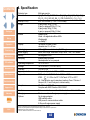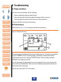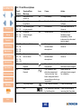
1
H2S CO CH4 Gas-Pro User & Operator Manual Gas-Pro Multi-gas monitor Click here for navigation instructions Click here fo contents list M07995/Eng Issue 8 Jan 2015 Contents NAVIGATION INSTRUCTIONS The symbols in the left-hand margin of each page of the manual will enable you to carry out the following functions: Contents Click on this button to display the Contents page. Click on this button to display the previous page. Click on this button to display the next page. Click on this button to display the previous view (use it to return from a reference jump). Click on this button to display next view (use it to return to a reference jump). Click this button to print some or all of the document (specific pages can be chosen). Exit !! Click this button to exit the User and Operator Manual. Press the Esc key to display normal Acrobat© Controls. CONTENTS PROLOGUE . . . . . . . . . . . . . . . . . . . . . . . . . . . . . . . . . . . . . . . . . . . . . . 7 Gas-Pro Overview. . . . . . . . . . . . . . . . . . . . . . . . . . . . . . . . . . . . . . . . . . . . . . . 7 Safety Information. . . . . . . . . . . . . . . . . . . . . . . . . . . . . . . . . . . . . . . . . 8 Unpacking . . . . . . . . . . . . . . . . . . . . . . . . . . . . . . . . . . . . . . . . . . . . . . 11 1.Set-up . . . . . . . . . . . . . . . . . . . . . . . . . . . . . . . . . . . . . . . . . . . . . . . 12 1.1 Prior to use. . . . . . . . . . . . . . . . . . . . . . . . . . . . . . . . . . . . . . . . . . . . . . . . . 12 1.2 Gas-Pro orientation. . . . . . . . . . . . . . . . . . . . . . . . . . . . . . . . . . . . . . . . . . 12 1.3 Charging. . . . . . . . . . . . . . . . . . . . . . . . . . . . . . . . . . . . . . . . . . . . . . . . . . . 13 1.4 Fitting a flow plate. . . . . . . . . . . . . . . . . . . . . . . . . . . . . . . . . . . . . . . . . . . 14 1.5 Quick view. . . . . . . . . . . . . . . . . . . . . . . . . . . . . . . . . . . . . . . . . . . . . . . . . 15 2.Operation . . . . . . . . . . . . . . . . . . . . . . . . . . . . . . . . . . . . . . . . . . . . 16 2.1 General. . . . . . . . . . . . . . . . . . . . . . . . . . . . . . . . . . . . . . . . . . . . . . . . . . . . 16 2.2 Turn on. . . . . . . . . . . . . . . . . . . . . . . . . . . . . . . . . . . . . . . . . . . . . . . . . . . . 16 2.3 Pump test. . . . . . . . . . . . . . . . . . . . . . . . . . . . . . . . . . . . . . . . . . . . . . . . . . 20 2.4 Detecting gas. . . . . . . . . . . . . . . . . . . . . . . . . . . . . . . . . . . . . . . . . . . . . . . 21 2.4.1 Diffusion monitoring. . . . . . . . . . . . . . . . . . . . . . . . . . . . . . . . . . . . . 21 2.4.2 Pumped mode. . . . . . . . . . . . . . . . . . . . . . . . . . . . . . . . . . . . . . . . . . 22 2.4.3 Manual sampling. . . . . . . . . . . . . . . . . . . . . . . . . . . . . . . . . . . . . . . . 23 2.4.3.1 Using the Hand Aspirator. . . . . . . . . . . . . . . . . . . . . . . . . . . . . 23 2.5 Alarms. . . . . . . . . . . . . . . . . . . . . . . . . . . . . . . . . . . . . . . . . . . . . . . . . . . . .24 2.5.1 Low battery alarm. . . . . . . . . . . . . . . . . . . . . . . . . . . . . . . . . . . . . . . 24 2.5.2 Instantaneous alarm. . . . . . . . . . . . . . . . . . . . . . . . . . . . . . . . . . . . . 24 2.5.3 Time weighted average alarm (TWA). . . . . . . . . . . . . . . . . . . . . . . . 24 2.5.4 Accepting and clearing alarms . . . . . . . . . . . . . . . . . . . . . . . . . . . . 25 Exit 3 2.5.5 Sensor types. . . . . . . . . . . . . . . . . . . . . . . . . . . . . . . . . . . . . . . . . . . 25 2.5.5.1 Oxygen sensors. . . . . . . . . . . . . . . . . . . . . . . . . . . . . . . . . . . . 25 2.5.5.2 Electro-chemical sensors. . . . . . . . . . . . . . . . . . . . . . . . . . . . . 25 2.5.5.3 Infra red sensors . . . . . . . . . . . . . . . . . . . . . . . . . . . . . . . . . . . 25 2.5.5.4 Pellistor sensors. . . . . . . . . . . . . . . . . . . . . . . . . . . . . . . . . . . . 26 2.5.5.5 Pellistor saver mode . . . . . . . . . . . . . . . . . . . . . . . . . . . . . 26 2.5.5.6 PID . . . . . . . . . . . . . . . . . . . . . . . . . . . . . . . . . . . . . . . . . . . . . 27 2.6 Gas-Pro functions. . . . . . . . . . . . . . . . . . . . . . . . . . . . . . . . . . . . . . . . . . . 28 2.6.1 Accessing the user menus. . . . . . . . . . . . . . . . . . . . . . . . . . . . . . . . 28 2.6.2 Home screen . . . . . . . . . . . . . . . . . . . . . . . . . . . . . . . . . . . . . . . . 28 2.6.3 Manual zero . . . . . . . . . . . . . . . . . . . . . . . . . . . . . . . . . . . . . . . . . 28 2.6.4 Time weighted average . . . . . . . . . . . . . . . . . . . . . . . . . . . . . . . . 28 2.6.5 Pre-entry check (PEC) . . . . . . . . . . . . . . . . . . . . . . . . . . . . . . . . . 29 2.6.5.1 Starting a Pre-entry check. . . . . . . . . . . . . . . . . . . . . . . . . . . . 29 2.6.5.2 Carrying out a Pre-entry check . . . . . . . . . . . . . . . . . . . . . . . . 30 2.6.6 Peak review . . . . . . . . . . . . . . . . . . . . . . . . . . . . . . . . . . . . . . . . . 31 2.6.7 Settings . . . . . . . . . . . . . . . . . . . . . . . . . . . . . . . . . . . . . . . . . . . . 31 2.6.7.1 User setting . . . . . . . . . . . . . . . . . . . . . . . . . . . . . . . . . . . . 31 2.6.7.2 Pump setting . . . . . . . . . . . . . . . . . . . . . . . . . . . . . . . . . . . 31 2.6.7.3 Sounder volume . . . . . . . . . . . . . . . . . . . . . . . . . . . . . . . . . 31 2.7 Shut down . . . . . . . . . . . . . . . . . . . . . . . . . . . . . . . . . . . . . . . . . . . . . . . . . 32 2.8 Additional Features. . . . . . . . . . . . . . . . . . . . . . . . . . . . . . . . . . . . . . . . . . 32 2.8.1 +ve Safety™. . . . . . . . . . . . . . . . . . . . . . . . . . . . . . . . . . . . . . . . . . . . 32 2.8.1.1 +ve Safety™ indicator meanings. . . . . . . . . . . . . . . . . . . . . . . 32 2.8.2 Data and event logging. . . . . . . . . . . . . . . . . . . . . . . . . . . . . . . . . . . 33 2.8.3 Bump/Pump functionality. . . . . . . . . . . . . . . . . . . . . . . . . . . . . . . . . 33 Exit 4 3. Gas testing and calibration. . . . . . . . . . . . . . . . . . . . . . . . . . . . . . 34 3.1 Introduction. . . . . . . . . . . . . . . . . . . . . . . . . . . . . . . . . . . . . . . . . . . . . . . . 34 3.2 Bump Test Functionality. . . . . . . . . . . . . . . . . . . . . . . . . . . . . . . . . . . . . . 35 3.2.1 Speedy bump. . . . . . . . . . . . . . . . . . . . . . . . . . . . . . . . . . . . . . . . . . . 36 3.2.1.1 Procedure . . . . . . . . . . . . . . . . . . . . . . . . . . . . . . . . . . . . . . . . 36 3.2.2 Smart bump. . . . . . . . . . . . . . . . . . . . . . . . . . . . . . . . . . . . . . . . . . . . 36 3.2.2.1 Procedure . . . . . . . . . . . . . . . . . . . . . . . . . . . . . . . . . . . . . . . . 36 3.2.3 Calibration after bump fail. . . . . . . . . . . . . . . . . . . . . . . . . . . . . . . . 37 3.2.3.1 Procedure . . . . . . . . . . . . . . . . . . . . . . . . . . . . . . . . . . . . . . . . 37 3.3 New sensor calibration/service. . . . . . . . . . . . . . . . . . . . . . . . . . . . . . . . 37 3.4 Gas test screen flow. . . . . . . . . . . . . . . . . . . . . . . . . . . . . . . . . . . . . . . . . 38 4. Icon overview. . . . . . . . . . . . . . . . . . . . . . . . . . . . . . . . . . . . . . . . . 39 5. Service and maintenance . . . . . . . . . . . . . . . . . . . . . . . . . . . . . . . 40 6. PC interface and Portables-Pro . . . . . . . . . . . . . . . . . . . . . . . . . . 41 6.1 General. . . . . . . . . . . . . . . . . . . . . . . . . . . . . . . . . . . . . . . . . . . . . . . . . . . . 41 6.2 PC interface cable. . . . . . . . . . . . . . . . . . . . . . . . . . . . . . . . . . . . . . . . . . . 41 7.Accessories . . . . . . . . . . . . . . . . . . . . . . . . . . . . . . . . . . . . . . . . . . 42 8. Specification. . . . . . . . . . . . . . . . . . . . . . . . . . . . . . . . . . . . . . . . . . 44 9.Troubleshooting. . . . . . . . . . . . . . . . . . . . . . . . . . . . . . . . . . . . . . . 45 9.1 Pump test failure. . . . . . . . . . . . . . . . . . . . . . . . . . . . . . . . . . . . . . . . . . . . 45 9.2 Fault screens. . . . . . . . . . . . . . . . . . . . . . . . . . . . . . . . . . . . . . . . . . . . . . . 45 9.2.1 Fault Descriptions. . . . . . . . . . . . . . . . . . . . . . . . . . . . . . . . . . . . . . . 46 9.2.2 Fault codes . . . . . . . . . . . . . . . . . . . . . . . . . . . . . . . . . . . . . . . . . . . . 48 Exit 5 10.Appendices. . . . . . . . . . . . . . . . . . . . . . . . . . . . . . . . . . . . . . . . . . . 49 10.1 Sensors . . . . . . . . . . . . . . . . . . . . . . . . . . . . . . . . . . . . . . . . . . . . . . . . . . 49 10.1.1 Toxic. . . . . . . . . . . . . . . . . . . . . . . . . . . . . . . . . . . . . . . . . . . . . . . . . 49 10.1.2 Flammable Pellistor Sensors. . . . . . . . . . . . . . . . . . . . . . . . . . . . . 50 10.1.3 Flammable IR Sensors. . . . . . . . . . . . . . . . . . . . . . . . . . . . . . . . . . 50 10.1.4 Oxygen. . . . . . . . . . . . . . . . . . . . . . . . . . . . . . . . . . . . . . . . . . . . . . . 50 10.1.5 IR. . . . . . . . . . . . . . . . . . . . . . . . . . . . . . . . . . . . . . . . . . . . . . . . . . . . 50 10.1.6 PID . . . . . . . . . . . . . . . . . . . . . . . . . . . . . . . . . . . . . . . . . . . . . . . . . . 50 10.2 Sensor Limitations . . . . . . . . . . . . . . . . . . . . . . . . . . . . . . . . . . . . . . . . . 51 10.3 Charging and run times . . . . . . . . . . . . . . . . . . . . . . . . . . . . . . . . . . . . . 52 10.4 Crowcon contacts. . . . . . . . . . . . . . . . . . . . . . . . . . . . . . . . . . . . . . . . . . 53 Warranty. . . . . . . . . . . . . . . . . . . . . . . . . . . . . . . . . . . . . . . . . . . . . . . . 54 Exit 6 Contents PROLOGUE Gas-Pro Overview Thank you for purchasing the new Gas-Pro. At Crowcon we recognise the need for reliable and robust personal monitors which are sized to be worn and simple to use. Prologue Set-up Gas-Pro is a portable monitor capable of detecting up to 5 gases in a compact and wearable design featuring an optional internal pump. Focused on users and fleet managers alike, Gas-Pro offers application focused solutions giving greater operating time and reduced set up time. Gas-Pro is classified for use in hazardous areas and gives loud and bright audible and visual alarm indications as well as a vibrate alert. The top mount display is backlit for ease of use, and the simple single button solution makes using and training quick and easy. Operation Gas testing Maintenance PC software Accessories Specification Troubleshooting Appendices Warranty Exit 7 Contents Safety Information • Gas-Pro is a hazardous area certified gas detector and as such must be operated and maintained in strict accordance with the instructions, warnings and label information included in this manual. Gas-Pro must be operated within the limitations stated. • Read and understand all instructions in the operation section of this manual prior to use. • Before use ensure that the equipment is in good condition, the enclosure is intact has not been damaged in any way. Prologue • If there is any damage to the equipment do not use, contact your local Crowcon office or agent for repair/replacement. Set-up • Do not disassemble or substitute components as this may impair intrinsic safety and invalidate safety certification. Operation Gas testing • Only genuine Crowcon replacement parts must be used; substitute components may invalidate certification and warranty of the Gas-Pro and accessories, reference “Service and Maintenance” section for details. • No live maintenance is permissible. • Observe all warnings and instructions marked on the unit and within this manual. Maintenance • Observe site health and safety procedures for gases being monitored and evacuation procedures. • Understand the screen display and alarm warnings prior to use. PC software • If this product is not working properly, read the troubleshooting guide and/or contact your local Crowcon office or agent, for details reference the ‘Crowcon Contacts’ section of the manual. Accessories • Ensure maintenance, service and calibration is carried out in accordance with the procedures in the manual and only by trained personnel. Specification • The Gas-Pro re-chargeable battery must only be charged in non-hazardous (safe) areas. • Only connect to Gas-Pro in a safe area for charging or communications. Troubleshooting • Gas-Pro must not be charged or have communication to the device, at ambient temperatures greater than +40°C. Appendices • Charging cable assemblies, whilst nominally providing a voltage of 6.5V, must not exceed a voltage of 9.1V as this may impair intrinsic safety and invalidate safety certification (Um=9.1V). Warranty • Communication cable assemblies, whilst nominally operating at a voltage of 3.0V TTL, must not exceed a voltage of 9.1V as this may impair intrinsic safety and invalidate safety certification (Um=9.1V). • The devices are intended for use in normal atmospheric conditions of temperature –20 °C to +55 °C; pressure 80 kPa (0,8 bar) to 110 kPa (1,1 bar); and air with normal oxygen content, typically 21 % v/v (volume/volume). Exit 8 Contents • Gas-Pro may be used in Zones 1 and 2, for Group llA, llB and llC gases and vapours and for Temperature Classes T1, T2, T3 and T4. (see Certification labels below). • Certification labels The certification marking is as follows: CH4 CH4 Ex d ia IIC T4 Gb Tamb: -20°C to +55°C IECEx ULD 11.0004X DEMKO 11ATEX1031772X T4 Tamb: -20°C to +55°C Prologue Set-up Operation Gas testing Maintenance FOR USE IN HAZARDOUS LOCATIONS, CLASS I, DIVISION 1, GROUPS A, B, C & D. ONLY AS TO INTRINSIC SAFETY 66Y6 WARNING DO NOT CHARGE THE BATTERY OR CONNECT TO THE EQUIPMENT IN A HAZARDOUS LOCATION. READ AND UNDERSTAND THE MANUAL BEFORE USE. 172 BROOK DRIVE MILTON PARK, ABINGDON OX14 4SD UNITED KINGDOM WARNING DO NOT CHARGE THE BATTERY OR CONNECT TO THE EQUIPMENT IN A HAZARDOUS LOCATION. READ AND UNDERSTAND THE MANUAL BEFORE USE. 172 BROOK DRIVE MILTON PARK, ABINGDON OX14 4SD UNITED KINGDOM Um = 9.1V Um = 9.1V 1180 1180 II 2 G ATEX/IECEx certification label UL certification label • Gas-Pro is certified for use in ambient temperatures in the range -20°C to +55°C (-4 to 131°F). PC software Accessories Specification Troubleshooting Appendices Warranty • Applicable Standards Refer to equipment marking for confirmation of applicable certification before use. IECEx IEC 60079-0:2004 4th Edition Electrical apparatus for explosive gas atmospheres Part 0: General requirements IEC 60079-0:2007 5th Edition Explosive atmospheres – Part 0: Equipment - General requirements IEC 60079-1:2007:6th Edition Explosive atmospheres – Part 1: Equipment protection by flameproof enclosures “d” IEC 60079-11:2006 5th Edition Explosive atmospheres - Part 11: Equipment protection by intrinsic safety “i” Ex d ia IIC T4 Gb Tamb -20°C to +55°C Exit IECEx ULD 11.0004X 9 Contents ATEX: EN 60079-0:2006 Electrical apparatus for explosive gas atmospheres Part 0: General requirements EN 60079-0:2009 Explosive atmospheres – Part 0: Equipment - General requirements EN 60079-1:2007 Explosive atmospheres – Part 1: Equipment protection by flameproof enclosures “d” Prologue Set-up Operation EN 60079-11:2007 Explosive atmospheres - Part 11: Equipment protection by intrinsic safety “i” II 2 G Ex d ia IIC T4 Gb Tamb -20°C to +55°C DEMKO 11 ATEX 1031772X Gas testing Maintenance PC software Accessories UL Gas detector use in hazardous locations Class 1 Division 1, Groups A, B, C and D only as to intrinsic safety. UL 913 UL 60079-0:2005 UL 60079-11:2002 7th Edition 4th Edition 1st Edition Specification Troubleshooting Appendices Warranty Exit 10 Contents Unpacking Remove the Gas-Pro from the packaging. The standard accessories are under the supporting trays. The following items will be included as standard: Box contents • Gas-Pro • Quick Start Guide Prologue Set-up Operation Gas testing Maintenance PC software Accessories Specification Troubleshooting Appendices • CD Manual • Calibration report The following items are optional: Optional items • Charger cradle • Charger lead (see Power & Communication Cables Technical Data) • Flow plate (standard for pumped units) ii ii ii ii ii If you have ordered a charger and/or cradle this will also be included in the box. Further accessories are available but will not be contained in the box (see Section 7). Gas-Pro in the off state can be left on charge indefinitely Should the unit be deep discharged, the charging indication will not be shown until the unit has been charging for 1 hour and the operator button has been pressed. When on and charging a warning will advise the user to turn the Gas-Pro off after 12 hours or remove from charge. Store the battery in a full state and recharge at least once every 3 months. Warranty Exit 11 Contents 1.Set-up 1.1 Prior to use Before use, the Gas-Pro should always be checked for any signs of physical damage. Gas-Pro uses a Lithium Ion (Li-ion) battery pack and should arrive with sufficient charge to be used straight out the box. However, if this is the first time of use, you may need to charge the battery to attain the full operating time (see Charging on page 13). Prologue Set-up Operation Gas testing For battery run times, see the table on page 52. ii The actual operating time will depend on the types of sensor installed. 1.2 Gas-Pro orientation Figure 1: Gas-Pro Á Maintenance PC software Accessories À Å È Â Ã Specification Troubleshooting Ä Æ Ç É Appendices Warranty À D-ring à Sounder Æ Sensor apertures É Charging cable Á Alarm bars Ä Operator button Ç Dual colour LCD display Certification label  +ve Safety™ indicator Å Pump inlet/outlet* È Alligator clip * Blanked for non-pumped unit. Exit 12 Contents 1.3 Charging Charging should only take place in non-hazardous (safe) areas. To charge, simply plug the cable À into the charging socket Á on the Gas-Pro and turn on the mains supply (see Figure 2 below). If a charging cradle or vehicle cradle is being used, ensure the Gas-Pro fits firmly on to the power connector. ii The charger must be able to supply 6.5V@ 450mA with an output voltage that does not exceed 9.1V (Um). Prologue Figure 2: Charger connection Set-up Operation Á Gas testing Maintenance PC software À Accessories Specification Troubleshooting Appendices Warranty Exit When off, to show the Gas-Pro is charging, both LEDs within the alarm bars will flash red and will change to green once fully charged. This state will continue until the trickle charge is complete. Charging will then terminate showing no indication. The screen will also show the battery icon filling in the middle of the screen when the Gas-Pro is off, and in the bottom left-hand corner when it is on. The battery icon contains a maximum of six segments to indicate the battery’s state of charge. For example, with three segments shown and a fourth flashing, the battery is 50% charged À, and when all six are shown, the battery is fully charged Á (see Figure 3 below). Figure 3: Charging indications À Á 13 Contents Prologue Set-up 1.4 Fitting a flow plate A flow plate can be used for a number of applications including pumped operation (remote sampling), manual gas test/calibration or for manual sampling. If the pumped flow plate is attached before turning the Gas-Pro on and the Gas-Pro includes a pump, a pump test will commence as part of the start up process (see Pump test on page 20). There are 3 types of flow plate: one for a Gas-Pro with internal pump, one for a Gas-Pro with no pump and a non-magnetic version for PC calibration or for manual sampling. Although there is no difference to the attachment procedure, they are not interchangeable (see Figure 4). The pumped flow plate has the symbol in the top left corner to aid recognition. Figure 4: Pumped and non pumped flow plates À Operation Gas testing Á  À Pumped flow plate Á Non pumped flow plate Maintenance PC software Accessories Specification Troubleshooting  PC Cal/Test Flow Plate Check the flow plate’s gasket is free from dirt and has not been damaged prior to fitting. To fit a flow plate, locate it over the Gas-Pro sensors as shown in Figure 5 and tighten the securing screw À. Figure 5: Fitting a flow plate À Appendices Warranty Exit The flow plate includes a quick connect fitting for attaching sample tubes and probes. 14 Contents 1.5 Quick view Even when the detector is off, users can display details about the configuration of the Gas-Pro by momentarily pressing the operator button for one audible blip. The LED to the left of the display will flash red once and the Quick view screen shown in Figure 6 below will be displayed for 10 seconds. Figure 6: Quick view display À Prologue Set-up  Á Operation Gas testing Maintenance PC software Accessories Specification À Gas type and unit detected Á Battery status  Quickview icon à ID or serial number à ii The +ve Safety™ LED status is also shown (see Figure 1). Troubleshooting Appendices Warranty Exit 15 Contents 2.Operation 2.1 General !! Before turning the Gas-Pro on, ensure it is in ‘clean air’ (i.e. outside, in normal air, away from any plant process or suspected gas location). This will allow the Gas-Pro to be zeroed using clean air as the base point. If the Gas-Pro is zeroed in contaminated air a false gas reading can result, or the zero could fail. Prologue Set-up Operation Gas testing Maintenance 2.2 Turn on In ‘clean air’, turn on the Gas-Pro by holding down the operator button for 3 audible blips. The GasPro will warm up, going through a series of automatic processes as follows: Firstly a test screen pattern will be generated. Watch this to ensure there are no missing pixels on your display screen. Whilst the Gas-Pro is warming up, two screens will be displayed. Figure 7: Initial screens at turn on PC software Accessories Specification Troubleshooting Appendices Warranty After a successful test cycle the LCD screen will remain green, the sounder and LEDs will indicate the Gas-Pro is healthy. ii ii ii A Gas-Pro fitted with a pump is configured as standard to start the pump automatically when switched on, provided that a flow plate is fitted. Such a Gas-Pro tests the pump automatically at this point (for more details on this, see Pump test on page 20). If the battery level is low, an alarm will sound, and the battery icon on the screen will be partial. Exit If a second ‘splash’ screen has been configured via Portables-Pro it will be shown next in the turn on sequence. 16 Contents If the Gas-Pro is configured for regular Gas Testing (Bump Test), the date of the last Gas Test will also be shown (for more information on Gas Testing, see Gas testing and calibration on page 34). Figure 8: Gas test due screen Prologue Set-up Operation Gas testing Maintenance The next screen indicates when the Gas-Pro was last calibrated. It also indicates when the next calibration is due with a warning symbol next to the number of days left, if this is less than 30 days. If the calibration due date has expired, the number of days figure is not displayed and the warning symbol flashes. Figure 9: Calibration due screen PC software Accessories Specification Troubleshooting Appendices Warranty If the calibration due lockout feature has been enabled the lockout icon Gas-Pro will not proceed past this point. Exit 17 will be displayed and the Contents The next screen (Figure 10) will display the current detector settings (for more information on these settings, see Gas-Pro functions on page 28). Figure 10: Current settings screen Prologue Set-up Operation Gas testing The Autozero Confirm screen will be displayed next. Figure 11: Autozero confirm screen Maintenance PC software Accessories Specification Troubleshooting Appendices An Autozero should not be performed unless the Gas-Pro is in clean air. Press the operator button to enter the Autozero mode, otherwise the countdown will progress and will not perform a zero. If the operator button is not pressed the countdown will complete and this function will be skipped. Warranty Exit 18 Contents When the autozero has finished or been skipped, the next screen is the home screen (Figure 12) and displays the gas levels. ii Figure 12 shown below is for 5 gases in clean air. À Figure 12: Home screen Prologue Set-up Operation Gas testing Maintenance PC software Accessories Specification Troubleshooting Á  À Gas type Á Unit  Level à Home Screen icon Ä Battery level Å Pump present à (rotating when on) Ä Å In ‘clean air’, CO2 and Oxygen levels are typically 0.04% and 20.9% respectively. In zero mode, these gases will actually run an ‘offset’ zero. The Gas-Pro is now ready for use. !! From the 1st November 2010, EN60079-29 part 1 has been harmonised under the ATEX directive 94/9/EC. Therefore to comply with the ATEX directive, portable apparatus sensing flammable gases should have a functional check with flammable gas before each day of use (see Gas testing and calibration on page 34). Other testing regimes may be employed depending on local circumstances. Appendices Warranty Exit 19 Contents 2.3 Pump test In the default configuration, a pumped Gas-Pro with a flow plate attached (see Fitting a flow plate on page 12) will run a pump test during the start up process. A pump test will also be run whenever a flow plate is attached during normal operation. ii ii If the Gas-Pro is configured for Bump functionality, the Bump/Pump prompt will be displayed if a flow plate is attached and a gas bump test is due or the Gas-Pro is placed in a Q-Test module during normal use (see Bump/Pump functionality on page 33). Prologue Set-up Operation Gas testing Prior to fitting, the flow plate’s gasket should be checked for any damage. The pump test ensures accurate sealing as well as monitoring pump performance. The user will need to cover the pump inlet À (see Figure 13 below) when prompted to do so by the symbol on the screen. Figure 13: Pump inlet Maintenance PC software À Accessories Specification Troubleshooting Appendices Warranty When the test has finished, the pump will either pass or fail . If the pump test takes place during start-up and the Gas-Pro passes, the pump will remain on and the start-up process will continue as normal. If the test is passed during normal use, the Gas-Pro will remain in the pumped mode until the flow plate is removed. On failing the pump test the fail screen will persist with an audible alert until the button is pressed and the test repeats OR the flow plate is removed and the Gas-Pro returns to unpumped operation. For further detail on failing a pump test see Pump test failure on page 45. Exit 20 Contents 2.4 Detecting gas When sampling an area that may contain water, use the ball float probe to reduce the potential for water travelling up the sample line. 2.4.1 Diffusion monitoring If you wish to monitor gases in ambient air for dangerous levels, the Gas-Pro can be worn by either clipping the strong alligator clip to clothing/overalls in the breathing zone or through the use of a chest harness. Prologue Set-up Operation Gas testing Maintenance In the default, non-alarm state, Gas-Pro’s sounder À will emit a beep every 10 secs, its confidence LEDs Á will flash green, the +ve Safety™ indicator  will show the current status, and the LCD display à will indicate it is running by flashing the icon. Figure 14: Gas-Pro indicators à Á  PC software Accessories Specification Troubleshooting À In the alarm state, Gas-Pro will vibrate, its sounder À will emit a rapid tone, the alarm LEDs Á will flash red and blue, the +ve Safety™ indicator  will be off in alarm, the LCD display à will also be red and highlight the gas in alarm. Appendices Warranty Exit 21 Contents 2.4.2 Pumped mode Pumped operation requires the use of the pumped flow plate which automatically activates the pump (see Bump/Pump functionality on page 33). Gas-Pro can either be worn or used with hoses and probes to sample from spaces prior to entry. The pump capacity in the Gas-Pro is 0.5l/m and will draw a sample of gas from 30m within 80 seconds. Please note the expected losses for some gases below. Please allow at least 3 seconds per meter of hose used. Tube Type Prologue Set-up Operation Gas testing Maintenance PC software Accessories Tube length Measurement CO (250ppm) H2S (25ppm) CH4 (2.5% VOL) CO2 (5% VOL) O2 (18% VOL) Standard (AC0201/03/05/10/20/30) Gas Name Carbon Monoxide Hydrogen Sulphide Methane Carbon Dioxide Oxygen 5 metres Loss 0ppm 0ppm 0% VOL 0% VOL 0% VOL Time 9s 10 s 10 s 9s 9s 10 metres Loss 0ppm 1ppm 0% VOL 0% VOL 0% VOL Time 20 s 20 s 20 s 20 s 20 s 30 metres Loss 1ppm 6ppm 0% VOL 0% VOL 0% VOL ii Time 79 s 78 s 78 s 79 s 79 s If Gas-Pro is operated in pumped mode in combination with an exhaust pipe, a set of bellows should be used inline (e.g. flow plate , 2cm maximum tube, bellows, 3000cm maximum tube). ii Gas-Pro also has a specific pre-entry mode (see Section 2.6.5 on page 29). Specification Troubleshooting Appendices Warranty Exit 22 Contents Prologue Set-up Operation Gas testing Maintenance 2.4.3 Manual sampling If the internal pump option has not been chosen the hand aspirator may be used for pre-entry checks and remote sampling. This is not however recommended for sample hoses longer than 5 meters due to the amount of time (and therefore squeezes) it would take to get a repeatable sample to the sensors. A water trap and filter should be used. 2.4.3.1 Using the Hand Aspirator The hose end of the hand aspirator should be attached to the exhaust of the un-pumped flow plate, a sensors covered warming will be shown and the user should accept this. The bulb should then be depressed whilst holding a finger over the inlet to ensure that a tight seal has been achieved. The detector will at this point likely go into alarm (this is due to the pressure effect on the oxygen sensor) and the bulb of the aspirator should not return to the rounded shape. If this does not happen – reposition the flow plate and repeat the test. Once the test is passed allow the O2 sensor to stabilise to 20.9% and then attach the required sample hose length to the inlet on the flow plate and commence sampling. Depress the aspirator bulb every other second in order to get a constant sample flow to the sensors. Every depression of the aspirator bulb should pull the sample approximately 25cm up the tube. Therefore to sample from a 5 meter hose – at least 20 aspirations will be required, however a minimum of 1 minute is recommended to ensure a stable sample is read. PC software If the Gas-Pro being used is fitted with a carbon monoxide sensor (CO) a 5% increase in reading is expected during this process due to the extra pressure placed on the sensor (ie if the sample being tested is 30ppm – the expected result onscreen will show 32ppm. Accessories If Gas-Pro is being used regularly for sampling, Crowcon strongly recommend the use of the internal pumped option to reduce time and potential for error. Specification ii Do not use the pumped flow plate for manual sampling. Troubleshooting Appendices Warranty Exit 23 Contents 2.5 Alarms The Gas-Pro has the following types of alarm: • Low battery • Instantaneous • Time weighted average (TWA) 2.5.1 Low battery alarm Prologue Set-up Operation Gas testing Maintenance PC software Accessories Specification Troubleshooting Appendices Warranty When the Gas-Pro warns of a low battery, the sounder will emit an audible double blip every 5 seconds and, if configured to do so, the +ve Safety™ LED will change state. This means the battery has at least 20 minutes of battery life remaining. After 20 minutes the Gas-Pro will enter full alarm state and the battery icon will flash empty. !! Users should finish their current activity and move to a safe area as the instrument will power off without further warning unless charged. 2.5.2 Instantaneous alarm The Gas-Pro will go into alarm immediately if the level of any of the gases it is configured to detect become outside acceptable limits. A minimum and maximum acceptable level is set for oxygen, for most other gases the Gas-Pro will go into alarm state 1 or 2 according to which level has been exceeded. In the alarm state, the ‘bell’ alarm symbol on the LCD screen will show a or to indicate which level of alarm has been triggered. In alarm, the sounder will emit a tone and the Gas-Pro will vibrate. The LEDs will flash red and blue, and the background of the LCD will change colour from green to red and the gas in alarm display will invert periodically. Symbols on the LCD will show the level and nature of the alarm. 2.5.3 Time weighted average alarm (TWA) When activated, the Gas-Pro begins a new record for each toxic gas being monitored where it stores information about gas levels detected. If the average levels detected over a period of time exceeds predetermined levels, the Gas-Pro will go into alarm. In the alarm state, the TWA symbol on the LCD screen will indicate a 15 minute or 8 hour limit . The sounder will emit a tone and the Gas-Pro will vibrate. The LEDs will flash red and blue, and the background of the LCD display will change colour from green to red. The LCD display will indicate the alarm has been triggered by exposure over time rather than instantaneously. Levels are set for a short period of 15 minutes and a longer one of 8 hours. !! ii TWA alarms cannot be cleared. (The 8 hour TWA can be reviewed in the user menu - see Section 2.6.4 on page 28). The TWA can only be cleared by turning the Gas-Pro off (see Shut down on page 32). Refer to Health and Safety guidelines on TWA alarms. Exit If TWA is monitored with the +ve safety™ configuration, the TWA +ve safety alert is only cleared by downloading the datalog via Portables-Pro. 24 Contents 2.5.4 Accepting and clearing alarms Setting Non-latched Prologue Set-up Operation Gas testing Maintenance PC software Accessories Specification Troubleshooting Appendices Warranty Alarm 1 Alarms will not be latched returning to non-alarm state without user acceptance Alarm 2 Alarm can be turned off only when gas has returned to acceptable levels Latch Accept Allows the user to silence alerts but remains in alarm. Once gas has returned to acceptable levels the user needs to accept the state. Alarm can be turned off only when gas has returned to acceptable levels Latched Alarm can be turned off only when gas has returned to acceptable levels ii Alarm can be turned off only when gas has returned to acceptable levels While in alarm, the Gas-Pro will continue to record levels of all the gases being monitored. 2.5.5 Sensor types The Gas-Pro can be fitted with the following sensor types: • Oxygen • Electro-chemical • Infra red (IR) • Pellistor • Photoionization Detector (PID) 2.5.5.1 Oxygen sensors These sensors are in the form of an electro-galvanic fuel cell which is an electrical device used to measure the concentration of oxygen gas in the ambient air. Set as default with both higher and lower alarm levels. 2.5.5.2 Electro-chemical sensors Electrochemical gas sensors measure the volume of a target gas by oxidising or reducing the target gas at an electrode and measuring the resulting current. 2.5.5.3 Infra red sensors Gas is pumped or diffuses into the sample chamber, and gas concentration is measured electrooptically by its absorption of a specific wavelength in the infrared (IR). Exit 25 Contents Prologue Set-up Operation Gas testing Maintenance 2.5.5.4 Pellistor sensors Pellistor sensors (or catalytic beads) are specifically designed to sense explosive gases. The detecting element consists of small “pellets” of catalyst loaded ceramic whose resistance changes in the presence of gas. 2.5.5.5 Pellistor saver mode While in saver mode and the subsequent stabilise time, the gas level displayed on the LCD screen will indicate over range. If the alarm is so severe as to cause a sensor over-range the Gas-Pro should have a gas test to ensure no lasting damage has occurred. Pellistor sensors can suffer degradation if powered while exposed to flammable gas concentrations of greater than 100% LEL, and also if exposed to high levels of H2S or silicones. To reduce the degradation the instrument the Gas-Pro employs a Pellistor saver mode. When the gas exceeds the saver threshold (user configurable: default 90% – 95%) then the detector will turn off the sensor for a minimum period of 3 minutes 20 seconds. After this time the sensor can be re-activated by a single click of the operator button. PC software Accessories Specification Troubleshooting Appendices After a stabilisation time, if the gas level still exceeds the threshold then the sensor will be turned off and the cycle starts again. !! From the 1st November 2010, EN60079-29 part 1 has been harmonised under the ATEX directive 94/9/EC. Therefore to comply with the ATEX directive, portable apparatus sensing flammable gases should have a functional check with gas before each day of use (see Gas testing and calibration on page 34). Other testing regimes may be employed depending on local circumstances. Warranty Exit 26 Contents 2.5.5.6 PID PID sensors are configured and calibrated to Isobutylene when manufactured. The PID sensor can be configured to detect Volatile Organic Compounds (VOC) other than Isobutylene by changing the correction factor in the PID sensor type options Details of how to change the VOC correction factor can be found in Portables-Pro user manual Gas-Pro fitted with a PID sensor may require periodic cleaning and calibration of the sensor to ensure correct performance in normal use. Prologue Set-up Operation Gas testing The sensor may need maintenance if any of the following occur: • The baseline is climbing after zeroing the sensor • The sensor becomes sensitive to humidity • The baseline is unstable or shifts when the sensor is moved • Sensitivity of the sensor has dropped Please refer to Crowcon application note PID-AN-001 for further details on maintenance and cleaning of the PID sensor. Maintenance PC software Accessories Specification Troubleshooting Appendices Warranty Exit 27 Contents 2.6 Gas-Pro functions The following can be selected from the Gas-Pro user menu: Home screen Manual zero Time weighted average (TWA) review Prologue Set-up Operation Gas testing Pre-entry check Peak review Settings menu 2.6.1 Accessing the user menus With the home screen displayed, double click the operator button to access the function menus. Maintenance PC software Accessories Specification Troubleshooting Appendices Warranty Single click the operator button to scroll right until the required menu icon is highlighted and then double click to select the function. 2.6.2 Home screen When this icon is selected, the Home screen will be displayed. 2.6.3 Manual zero This function should only be carried out in ‘clean air’ and allows the Gas-Pro to be zeroed at any time. Certain operations will only take place if the Gas-Pro has been recently zeroed . For example, if configured to do so, Gas-Pro will progress to a calibration after failing a gas test if the unit has been manually zeroed in the last 15 minutes. 2.6.4 Time weighted average Exit This function allows the 8 hour TWA to be reviewed. For more details on the settings, see Time weighted average alarm (TWA) on page 24. 28 Contents 2.6.5 Pre-entry check (PEC) This function is intended for sampling air of unknown quality before gaining access to it (e.g. going under ground through a manhole cover) thereby avoiding unnecessary exposure. ii ii The Gas-Pro (and any sampling probe) should be in a clean air when the PEC starts and finishes so the TWA accumulation should be insignificant. Prologue Set-up Operation Gas testing Maintenance PC software Accessories If Gas-Pro is operated in pumped mode in combination with an exhaust pipe, a set of bellows should be used inline (e.g. flow plate , 2cm maximum tube, bellows, 3000cm maximum tube). PEC is a three stage process: sampling, peak and purge. There is a 5 minute timeout on each PEC stage, with a timeout moving the instrument through the stages – a timeout from the purge screen takes the instrument back to the home screen. This gives a total PEC timeout time of 15 minutes. This timing is deliberate: the STWA time period is 15 minutes so this ensures that if the gas level at the operator exceeds the level for an STWA alarm then the alarm will occur on completion of the PEC. 2.6.5.1 Starting a Pre-entry check ii If the Gas-Pro is in alarm, the Pre-entry check will not appear on the menu. Before you start the Pre-entry check, ensure you are ready to start the test (i.e. any flow plate, sampling probe or hand aspirator are fitted to the Gas-Pro as required). From the home screen, double click the operator button to enter the menu selection screen. Specification Troubleshooting Once there, single click to scroll to the right until Pre-entry check menu symbol is highlighted with a box. Appendices Warranty Exit Double click to enter the PEC sampling stage. A countdown screen will be displayed. Single click the operator button to start sampling. If the countdown finishes, the Gas-Pro will return to the home screen. 29 Contents 2.6.5.2 Carrying out a Pre-entry check The Gas-Pro will remain in the sampling stage for a maximum of 5 minutes. Whilst the sampling screen is displayed, it will show the real time gas levels. The alarms will continue to function during this stage and a single click of the operator button will accept these. Prologue Set-up Operation Gas testing Maintenance The PEC can be moved to the peak stage at any time before the 5 minute timeout by double clicking the operator button. Peak readings registered during the Pre-entry check will be logged as events. ii Any peak reading sampled during this stage will not be added to the detector’s cumulative monitoring data and thus will not affect the TWA calculations. The Gas-Pro will remain in the peak stage for a maximum of 5 minutes. When accessing the Peak Review screen the peak displayed will be the gas peak (trough for O2) seen in the selected time period; this will include gas levels seen during any PECs in the time period. PC software The PEC can be moved to the purge stage at any time before the 5 minute timeout by double clicking the operator button. Accessories The Gas-Pro will remain in the purge stage for a maximum of 5 minutes. Specification Troubleshooting Appendices ii Before the purge stage ends, move to clean air. To end the purge stage at any time before the 5 minute timeout double click the operator button. A 10 second countdown screen will be displayed. To confirm the end of the purge stage single click the operator button within the 10 seconds or the purge will continue. Warranty Exit 30 Contents 2.6.6 Peak review Select this option from the Menu Screen to see the highest level of each gas detected during the session. The menu offers the choice to display the peak gas level since the Gas-Pro was powered up , that occurred during the last 8 hours , or during the last 12 hours . The peaks are cleared when Gas-Pro is turned off. 2.6.7 Settings The following settings can be altered by the user: Prologue Set-up Operation Gas testing Maintenance PC software Accessories Specification Troubleshooting Appendices Warranty 2.6.7.1 User setting Up to 5 different users can be loaded into Gas-Pro using the Portables-Pro PC application. Double click the operator button to select the function. The screen will display the 5 user selectable icons (À to Ä). Single click the operator button until the required user number is highlighted and then double click to select it. The screen will return to the settings menu and after a few seconds will display the home screen. Gas-Pro will create an event when the user is changed allowing traceability of the user. 2.6.7.2 Pump setting This function, which is only present if the Gas-Pro has an internal pump, allows the user to turn the pump on or off. Double click the operator button to select the function. Single click the operator button to highlight the required symbol ( to turn the pump on or to turn the pump off) and then double click. The screen will return to the settings menu and after a few seconds will display the home screen. If a flow plate is attached a ‘sensor covered’ icon will be shown . 2.6.7.3 Sounder volume This function allows the user to change the sounder volume. Double click the operator button to select the function. Single click the operator button to highlight the required symbol ( for high volume (98dB) or for low volume (95dB)) then double click. The screen will return to the settings menu and after a few seconds will display the home screen. Exit 31 Contents 2.7 Shut down To turn the Gas-Pro off, press and hold the operator button. A 4 second countdown will start. Hold the button down until the countdown has finished and the Gas-Pro will shut down. If you release the button before the countdown has finished, the Gas-Pro will resume operation. 2.8 Additional Features The Gas-Pro can be configured to allow and/or change the following features: Prologue Set-up Operation Gas testing Maintenance 2.8.1 +ve Safety™ +ve Safety™ (Positive Safety) provides positive confirmation of detector status prior to deployment, in the field or on return from site. The front mount tri-colour LED gives the Safety Manager or Supervisor the ability to see the status of the Operator’s detector giving unrivalled visibility of the status of detectors deployed. 2.8.1.1 +ve Safety™ indicator meanings Green flash Detector is compliant to the site or user specific requirements as set within the configuration. PC software Accessories Specification Amber double flash Detector is operational but requires attention. One or more of the pre-set flags has been triggered to change the status. Troubleshooting Appendices Warranty Red constant Indicates the detector is not within the specified criteria for use and should not be used. Gas-Pro is set at default to the ‘Classic’ setting but can be configured to organisational requirements through the use of Portables-Pro and/or the I-Test. Exit 32 Contents 2.8.2 Data and event logging The data log records gas levels for all sensors and has capacity for 45,000 logs (125hrs @10 sec intervals). Threshold levels can be set using Portables-Pro, extending log capabilities. The data log interval is set as part of the Gas-Pro configuration and can be adjusted using Portables-Pro. Event logging records significant events occurring during Gas-Pro operation. Events include: Prologue Set-up Operation Gas testing Maintenance PC software Accessories Specification • On • Off • Configuration change • Fault • User Acknowledgements • Low battery • Time change/set • Pellistor saver • Alarm 1 • Alarm 2 • STWA • LTWA • Zero • Calibration • Gas Test • Zero (auto or manual) • Log upload (data/event) • PEC • PEC Peaks • User changed The event log has a capacity of at least 1000 events. 2.8.3 Bump/Pump functionality If the Gas-Pro is configured for Bump/Pump functionality, then by placing the Gas-Pro in a Q-Test module or attaching a flow plate (with the Gas-Pro home screen displayed), the Bump/Pump screen will be displayed (see Figure 15 below). Figure 15: Bump/Pump screen Troubleshooting Appendices Warranty Exit Click the operator button to highlight for Pump or for Bump testing and then double click to select (see Pump test on page 20 or Speedy bump on page 36 and Smart bump on page 36 for Bump details). 33 Contents 3.Gas testing and calibration 3.1 Introduction Crowcon recommends regular gas tests (also known as bump tests) to confirm sensor operation. This involves applying a known composition of the correct gas to each sensor to verify sensor response and alarm function. Organisational specific Health and Safety regulations should be adhered to, and a number of flexible and simple solutions are available. Prologue Set-up Operation Gas testing Maintenance PC software Gas-Pro offers two types of bump test. A speedy bump test which is a gas test to the first alarm level and smart bump test, a gas test to a specified level of test gas. In addition if any channel fails speedy bump or smart bump then Gas-Pro can be configured to perform a bump fail calibration. Gas-Pro can be configured to automatically perform the following options: • No Calibration or Bump (default configuration) • Bump (Speedy or Smart) • Bump then calibration after bump fail (calibration can be optional on a bump test pass) • The configuration items differ per region and can be set with Portables-Pro to match user requirements. This bump test and calibration functionality can be implemented with of any of the following options. Specification Q-Test Quick and simple in-field gas test and calibration solution. Providing off-site testing for remote locations where power is not always available or practical. Simple to use and easy to repeat Q-Test reduces set-up, training requirements and space needed. Troubleshooting Powered Q-Test allows gives a permanent home to monitors as it can be mounted in a vehicle and easily powered via a standard in-vehicle power socket. Accessories Appendices Warranty I-Test Intelligent wall or desk mount gas test and calibration solution. Suitable for small and large fleet users alike, I-Test offers simple fully managed testing with data capture as well as the ability to update configurations. Flow Plate Gas-Pro can also be tested simply by using the flow plate and applying gas. Exit ii If Gas-Pro is operated in pumped mode in combination with an exhaust pipe, a set of bellows should be used inline (e.g. flow plate , 2cm maximum tube, bellows, 3000cm maximum tube) 34 Contents !! From the 1st November 2010, EN60079-29 part 1 has been harmonised under the ATEX directive 94/9/EC. Therefore to comply with the ATEX directive, portable apparatus sensing flammable gases should have a functional check with gas before each day of use. Other testing regimes may be employed depending on local circumstances. 3.2 Bump Test Functionality As part of the bump testing functionality Gas-Pro offers the ability to allocate gas sensors fitted to the GasPro into different ‘bump test groups’. These groups apply to both the speedy and smart bump functionality. Prologue Set-up Operation Gas testing The groups available are ‘Daily’ and ‘Intermittent’, these can be configured via Portables-Pro. This allows a different gas test regime to be applied for different sensors inline with site/company procedures. The information below explains this in greater detail: If the sensors are grouped into the ‘Intermittent1’ group with, for example, a 90 day interval (this interval is configurable in Portables-Pro), Gas-Pro will inform the user a bump test is due on the 90th day of use. This is indicated by a gas test due warning on the Gas-Pro screen during start up. Figure 16: Gas test due screen Maintenance PC software Accessories Specification Troubleshooting Appendices Warranty Gas-Pro will not inform the user of a need for a gas test until the interval period from the last successful bump has expired. However on applying a magnetised flow plate, or placing Gas-Pro into the Q-Test the user will be given the option to complete a gas test (or proceed to pumped operation). If the sensors are grouped into the ‘Daily’ group, the Gas-Pro will inform the user a bump test is due at the start of each working day (actually every 24 hrs). This is indicated by a gas test due warning on the Gas-Pro screen during start up. If Gas-Pro is turned off and on again within 24 hours of the gas test, the Gas-Pro will not inform the user of a need for a bump test. However on applying a magnetised flow plate, or placing Gas-Pro into the Q-Test the user will be given the option to complete a gas test (or proceed to pumped operation). Exit 1 The PID sensor can only be allocated to the ‘intermittent’ group; daily group is not available for PID sensors. The PID sensor must also be the only sensor in the intermittent group for the bump test functionality to operate correctly. 35 Contents 3.2.1 Speedy bump A speedy bump tests the Gas-Pro to first alarm level. Gas is presented across/over the sensor for a designated time (dependent on sensor gas type) during which alarm level one should be activated. This is deemed a pass if the detector goes into alarm and the detector is functioning (sounder, LED’s and vibrator, verified by the user). It is a fail if the detector does not go into alarm. Prologue Set-up Operation Gas testing Maintenance PC software Accessories Specification Troubleshooting Appendices Warranty 3.2.1.1 Procedure XX Either place the Gas-Pro in a Q-Test module or attach a flow plate to the Gas-Pro. XX Select Bump (see Bump/Pump functionality on page 33). The screen will show ‘Gas on’. XX Attach the gas bottle and turn it on. XX After a time (depicted by a time bar at the base of the display), the display will show if the gas(es) being tested have passed or failed . Gases not being tested will display [ ]. The test will end before the preset time if all gases being tested pass. * 3.2.2 Smart bump A smart bump tests that the Gas-Pro responds correctly to a specified level of test gas. Gas is passed over/across the sensors and a predicted response is expected within a time window dependant on the sensor response time. The test is passed if the gas level indicated by the detector is within pre-specified limits within this time window (the parameters of this test are configurable via Portables-Pro). 3.2.2.1 Procedure XX Either place the Gas-Pro in a Q-Test module or attach a flow plate to the Gas-Pro. XX Select Bump (see Bump/Pump functionality on page 33). The screen will show ‘Gas on’. XX Attach the gas bottle and turn it on. XX After a time (depicted by a time bar at the base of the display), the display will show if the gas(es) being tested have passed or failed . Gases not being tested will display [ ]. * (Note: Smart bump functionality is not available for the PID sensor. If Gas-Pro is configured for smart bump only a speedy bump will be performed on the PID sensor) Exit 36 Contents 3.2.3 Calibration after bump fail If any channel fails speedy bump or smart bump then Gas-Pro can be configured (via Portables-Pro) to perform a ‘calibration after bump fail’ immediately after the test failure. ii Calibration should only be performed with appropriately accurate gas. As this test immediately follows a speedy or smart bump, if ‘calibration after bump fail’ is configured the speedy or smart bump test will need to undertaken with calibration quality gas. Prologue Set-up ii ii Ensure the gas applied matches the configuration settings in the Gas-Pro or the test will fail. This can be done via Portables-Pro. Should a flammable sensor be fitted, check the label for the original calibration target. 3.2.3.1 Procedure Operation Gas testing Maintenance PC software • If calibration is intended, the instrument should have been zeroed manually within 15 minutes prior to the calibration attempt. • Following a bump test failure, leave the instrument in the Q-test module or with the flow plate attached and the gas on. • Wait for the calibration result screen indicated by the or . • The Gas-Pro then returns to normal operation. Accessories During this process the new calibration values are stored to the instrument memory and the calibration dates are advanced by the configured interval – commonly 1 month as the Gas-Pro has not been through a formal service/calibration routine (dependant upon region/setting). Specification If the gas test calibration fails this may be indicative of a more serious sensor issue, including the need to replace sensors. The instrument should then be serviced. Troubleshooting Appendices Warranty 3.3 New sensor calibration/service Servicing or the fitment of a new sensor can only be undertaken by a suitably trained technician using the PC software and the appropriate gases. In addition calibration should be performed as required by local or organisational regulations. In the absence of suitable evidence, such as a field assessment by a competent person, Crowcon recommend regular service and calibration every 6 months. Exit 37 Contents 3.4 Gas test screen flow The following sequence of screen shots should be viewed with reference to the sections on ‘Speedy Bump’, ‘Smart Bump’ & ‘Calibration after bump fail‘. The screen shots show the general flow of the gas test functionality dependant upon the actual test and the decisions made. Figure 17: Gas test screen flow Prologue Set-up Bump/Pump Gas Groups Gas On Operation Gas Off Gas testing Maintenance Pass One gas fail Fail PC software Accessories If enabled & manual zero <15mins prior Calibration after bump fail Specification Troubleshooting Pass Fail Appendices Warranty Exit 38 One gas fail Contents 4.Icon overview The table below details the icons shown during regular operation as well as warning messages. This table is intended as a quick overview please refer to specific functional sections within this manual for further details. Icon Prologue Set-up Operation Gas testing Maintenance PC software Accessories Description Icon Description Signifies ‘home’ screen Indicates ‘Battery’ information Indicates ‘Zero’ functionality Indicates a ‘Warning’ information Indicates ‘Pre Entry Check’ (PEC) functionality Indicates ‘Sounder’ functionality Indicates ‘Time Weighted Average’ (TWA) Indicates ‘Settings ‘ functionality Indicates ‘Pump’ fitment/operation Indicates ‘Peak’ functionality Indicates specified ‘User’ Indicates a ‘Gas Test’ information Indicates ‘Test Passed’ Indicates unit ‘Off’ functionality Time Date Indicates ‘Calibration’ information Indicates an ‘Alarm’ Specification Troubleshooting Appendices Warranty Exit 39 Contents 5.Service and maintenance Gas-Pro is designed to require minimal service and maintenance. As with all electrochemical sensors however, these will require periodic replacement. ii Ensure maintenance, service and calibration are carried out in accordance with the procedures in the manual and only by trained personnel. Prologue For further service or maintenance, contact your local Crowcon agent or regional office, for details reference the ‘Crowcon Contacts’ section of the manual. Set-up Operation Gas testing Maintenance PC software Accessories Specification Troubleshooting Appendices Warranty Exit 40 Contents 6.PC interface and Portables-Pro 6.1 General A number of differing variants of the software are available. The functionality of these variants ranges from viewing readings only, through to configuration and calibration. Please speak to Crowcon to determine which variant of software is appropriate for your requirements. Prologue Set-up Operation Gas testing Maintenance PC software Accessories Specification Troubleshooting Gas-Pro has many configurable features, the majority of these can be set using PC interface software. The Gas-Pro is delivered with factory set regional defaults, for example: • Alarm 2: latched • Volume: standard (95 dB) • Pump/bump: on • Bump: on • Calibrate: every 6 months • Autozero: on • Confidence: blip and flash • +ve Safety™: ‘Classic’ setting Please refer to the Calibration certificate supplied with the Gas-Pro for individual settings. As well as displaying real time gas level data and signalling instantaneous and time weighted average alarms, the Gas-Pro records events and gas levels. Using the I-test available from Crowcon, or by connecting the Gas-Pro to a computer (see Section 6.2, PC interface cable), this data can be collected and viewed. 6.2 PC interface cable Portables-Pro allows the download and viewing of data and event logs from the Gas-Pro using an interface cable via the USB socket on a laptop or desktop computer. Appendices Warranty ii Please see Portables-Pro instructions for details. Exit 41 Contents 7.Accessories Part Number CH0100 Description Multiregion power lead (includes CH0101 and CH0102) CH0101 Multiregion power supply CH0102 Charging lead CH0103 USB communications lead (not powered) CH0104 USB communication and power lead Prologue CH0105 Gas-Pro charger cradle (no power) CH0106 Vehicle charging adaptor (use with CH0102) Set-up CH0107 5 Way multi-region power supply (Note: only for use with charging leads with serial numbers greater than Wxxxxx) CH0200 INMETRO multi-region power lead (includes CH0101 and CH0202) CH0202 INMETRO Charging lead CH0203 INMETRO USB communications lead (not powered) CH0204 INMETRO USB communication and power lead AC0100 Gas-Pro pumped flow plate AC0101 Gas-Pro unpumped flow plate AC0201 1M Standard tubing (includes tube insert) AC0203 3M Standard tubing (includes tube insert) Accessories AC0205 5M Standard tubing (includes tube insert) AC0210 10M Standard tubing (includes tube insert) Specification AC0220 20M Standard tubing (includes tube insert) AC0230 30M Standard tubing (includes tube insert) Troubleshooting AC0500 Tube insert (connection from tube to flow plate) X 10 AC0511 Elbow tube insert (connection from tube to flow plate) X 10 Appendices AC0506 Chest harness plate AC0507 Chest harness straps (2 per pack) Warranty AC0508 Single strap AC0509 6M Drop line (includes D-ring clip) AC0501 Inline filter (for pumped units) AC0502 Water trap including filter AC0504 Hand aspirator bulb SS0726 Exhaust Bellows Operation Gas testing Maintenance PC software Exit 42 Contents Part Number AC0301 Description 1m reactive gas tubing (Tygothane® 3.2mm ID including tube insert) AC0303 3m reactive gas tubing (Tygothane® 3.2mm ID including tube insert) AC0512 Ball float probe AC0103 Calibration flow plate for PC Calibration (no magnet) Prologue Set-up Operation Gas testing Maintenance PC software Accessories Specification Troubleshooting Appendices Warranty Exit 43 Contents 8.Specification Detector type Gases* Size (d x l x w) Weight Prologue Alarms Set-up Operation Gas testing Maintenance PC software Accessories Specification Display Data logging Event logging Battery Sampling Operating temperature Storage Humidity Ingress protection Approvals Troubleshooting Appendices Warranty Exit Compliance Interface Charging Options Multi-gas monitor O2, H2S, CO, CO2, FLAM Pellistor (CH4, C5H12, C3H8, C4H10, C2H4, C2H2), SO2, CL2, CLO2, NO, NO2, NH3, O3, PID, FLAM IR (CH4, C5H12, C3H8) 43 x 130 x 84 mm (1.7 x 5.1 x 3.3 inches) 5 gas (pump) 362g (12.7oz) 5 gas (un pumped) 333g (11.7oz) 4 gas (pump) 340g (11.9oz) 4 gas (un pumped) 309g (10.8oz) Audible>95dB Visual – all angle dual red/blue LEDs Vibrating alert +ve Safety™ Top mount for ease of view viewable size 25 x 50 mm 125hrs @10 second intervals (45,000 logs) Alarm, over range, calibration, bump, on/off, TWA, 1000 events Rechargeable li-ion Internal pump as option Hand aspirator for non pumped -20°C to +55°C -25°C to +65°C (-13°F to +149°F) 10 to 95 % RH Independently tested to IP65 and IP67 IECEx : Ex d ia IIC T4 Gb Tamb -20°C to +55°C ATEX: II 2 G Ex d ia IIC T4 Gb Tamb -20°C to +55°C UL : Gas detector use in hazardous locations Class 1 Division 1 Groups A, B, C and D only as to intrinsic safety CE, FCC and ICES-003 Complies with EMC Directive 2004/108/EC Data connection for use with calibration stations & direct to PC Direct connect to multi-region power supply Car charging adapter USB interface cable USB power & communications cable 5 Way multi-region power supply * Gases not available in Gas-Pro with the internal pump option are CL2, CLO2 & O3 Sensors may be degraded at the higher temperatures subject to individual sensor specifications Dependant upon sensor configuration Gas-Pro’s fitted with a PID sensor are rated to IP65 only 44 Contents 9.Troubleshooting 9.1 Pump test failure In the event of a pump test failure, check the following: • Ensure a pumped flow plate was used for the test • Remove the flow plate and check the gasket for damage (scratches, tears, etc.) • Run the test again and ensure the test is carried out in the required time Prologue Set-up Operation If the pump still fails the test it may require servicing. 9.2 Fault screens A fault screen (see Figure 18 for an example) overwrites the normal screen. Figure 18: Example fault screen Gas testing Maintenance PC software Accessories Á  À Specification Troubleshooting Appendices Warranty The warning triangle À indicates faults that can be rectified by the user. The symbol is accompanied by the text “WARNING” below. The warning triangle is replaced by a spanner and screwdriver for faults which require service and the text “SERVICE” below. For the low battery warning the “WARNING” text is replaced by “ALERT”. The clock and calendar Á indicates that this is a time and date fault. The icons vary for each fault some of which are illustrated below. These icons can be replaced by the gas name in the case of a fault associated with a gas channel. Each fault has a fault code  (21 in this example). Exit 45 Contents Prologue Set-up 9.2.1 Fault Descriptions Fault codes Symtom/Error Message 0 or 9 Instrument won’t switch on. N/A Icon Cause Action NA Flat Battery. Recharge battery. No confidence beep/flash. NA Function disabled. Reconfigure with PC software. 26 - 30, 58 - 62 Gas Reading with no gas present. NA Zero drifted. Zero the instrument in clean air. 34 - 38, 50- 54, 58 - 62 Unstable/ inaccurate gas reading. NA Sensor failure. Do not use; exit hazardous area immediately. Send instrument to authorised service agent. 26 - 30, 34 - 38, 50 - 54, 58 - 62 Autozero failed. Zeroing in a contaminated atmosphere. Switch off and restart in clean air. 26 - 30, 34 - 38, 50 - 54, 58 - 62 Cannot autozero due to alarm. Zeroing in a contaminated atmosphere. Switch off and restart in clean air. 67 Calibration Expired. The calibration due date has passed. Send instrument to authorised service agent. 25 Calibration Expired The calibration due Send monitor to date has passed and authorised service agent “lock on cal due” has for calibration. been configured which causes the monitor to go inoperable*. 69 The pump stops. The Pump is blocked. 70 N/A The sensors are blocked Clear the blockage by by the flow plate. removing the flow plate. Operation Gas testing Maintenance PC software Accessories Specification Troubleshooting Appendices Warranty Exit 46 Clear the blockage. Contents Prologue Set-up Fault codes Symtom/Error Message 0 or 9 Cause Action Display shows empty battery symbol during startup. Battery depleted. Recharge battery. 73 Switched on and fully charged. Unit full and on charge for over 12 hrs. Remove Gas-Pro from charge. N/A Cannot switch off. Instrument configured for “No switch off in alarm”. Move to clean air then switch off. N/A Charger is plugged in but no display. Battery has been deep discharged and insufficient charge to power up display. Keep instrument on charge and eventually it will respond to single button push for quick view, after which it will display the charging symbol. 21 Time and Date error during startup. Battery has been deep discharged and the internal clock has stopped. Recharge battery. Then when charged correct the clock using the PC software. N/A Pump not active. NA The flow plate is not fitted and the pump is activated by the flow plate. Fit the flow plate and select pump if necessary. N/A Pump fails check when activated. NA The pump check tests the pump suction and leaks in the gas path. Check for the correct fitting of the flow plate and the seal of the gasket and tubing. Operation Icon NA Gas testing Maintenance PC software Accessories Specification Troubleshooting Appendices Re-activate the pump and block the gas path. Warranty 66 Gas Test Due. The monitor has not been gas tested in the defined period. Exit 47 The Gas Test is due. Contents Fault codes Symtom/Error Message N/A 71 Cause Action Bump Test Fail Lock. The monitor has not been gas tested in the defined period and the gas test lock function has been activated. The monitor needs calibration. Battery low Battery Low (about 20 to 30 minutes before switch off) Exit the hazardous area as soon as possible and recharge battery. Prologue Icon Set-up Operation Gas testing 9.2.2 Fault codes The following fault codes are not fixable by the user and the instrument should be sent to an authorised service agent:Fault code 4,5,6,7,8,11,12,13,14,15,16,17,19,20,25,26,27,28,29,30,50,51,52,53,54. Maintenance PC software Accessories Specification Troubleshooting Appendices Warranty Exit 48 Contents 10. Appendices 10.1 Sensors 10.1.1 Toxic Prologue Set-up Operation Gas testing Maintenance Gas CO/H2S Crowcon Sensor part no SS0300 Range 0-500/0-100PPM NH3 SS0306 0-100PPM CL2 SS0305 0-5PPM CL02 SS0308 0-1PPM SO2 SS0304 0-20PPM O3 SS0309 0-1PPM CO SS0301 0-500PPM CO SS0301 0-2000PPM CO SS0302 H 2S SS0303 0-2000PPM (H2 Filtered) NO SS0310 0-100PPM NO2 SS0311 0-20PPM 0-100PPM PC software Accessories Specification Troubleshooting Appendices Warranty Exit 49 Contents Prologue Set-up 10.1.2 Flammable Pellistor Sensors ii Flammable sensors MUST only be used with the PCB P/N as detailed below in the ‘PCB P/N Suitability” Column. Failure to do so may impair intrinsic safety and invalidate safety certification. Gas Crowcon Sensor Part No. Range Crowcon PCB P/N Suitability Methane SS0101 0-100% LEL S013021, S013022, S013024 Pentane SS0101 0-100% LEL S013021, S013022, S013024 Butane SS0101 0-100% LEL S013021, S013022, S013024 Ethylene SS0101 0-100% LEL S013021, S013022, S013024 Propane SS0101 0-100% LEL S013021, S013022, S013024 Acetylene SS0101 0-100% LEL S013021, S013022, S013024 Operation 10.1.3 Flammable IR Sensors Gas testing Maintenance PC software Accessories Specification Troubleshooting Appendices Gas Crowcon Sensor Part No. Range Methane SS0201 0-100% LEL Pentane SS0201 0-100% LEL Propane SS0201 0-100% LEL 10.1.4 Oxygen Gas Crowcon Sensor Part No. Range O2 SS0500 0-25% VOL (2 years) Gas Crowcon Sensor Part No. Range CO2 SS0280 0-5% VOL (2-5% for indication) Gas Crowcon Sensor Part No. Range PID SS0600 0 -1000ppm 10.1.5 IR Warranty 10.1.6 PID Exit 50 Contents Prologue Set-up Operation Gas testing 10.2 Sensor Limitations The instrument is not suitable for use in ambient temperatures above 55°C and electrochemical toxic gas sensors may be degraded, reducing life at these temperatures. Water should not be allowed to collect on the sensors as this may impede gas diffusion. Use with care in wet or humid environments where water may condense on the sensors, and check response after use. Persistent exposure to high levels of toxic gas can shorten the life of toxic sensors. Toxic sensors may also be cross-sensitive to gases other than their specific target gas, and hence the presence of other gases may cause the sensor to respond. If unsure, contact Crowcon or your local agent. Use of high power radio transmitters in close proximity to the instrument may exceed RFI immunity levels and cause erroneous indications. If such problems are experienced, remove antennae to a reasonable distance from the instrument (e.g. 30 cm). Standard units detect flammable gases using a catalytic flammable sensor which operates in the presence of oxygen. It is advisable to check the oxygen concentration as well as the flammable gas concentration before entering a confined space. Oxygen levels below 10% will reduce a flammable gas reading. Maintenance The performance of catalytic sensors may be permanently degraded if exposed to silicones, sulphur containing gases (such as H2S), lead or chlorine compounds (including chlorinated hydrocarbons). PC software The performance of the PID sensor depends on the environment that is being measured. If measuring high VOC concentrations where particulates are present in high concentrations check calibration frequently and if the sensor has lost sensitivity, refer to the application note PID-AN-001 for maintenance instructions. Accessories Specification Troubleshooting Appendices Warranty Exit 51 Contents Prologue Set-up Operation 10.3 Charging and run times The table below indicates run times which can be expected following a full charge discharge cycle. Configuration Run Time O2,CO/H2S, Pellistor, CO2 (IR) 11 hrs Pumped O2,CO/H2S, Pellistor, CO2 (IR) 10 hrs O2,CO/H2S, Pellistor 14 hrs Pumped O2,CO/H2S, Pellistor 13 hrs Run time is equal to the expected operating time following a full charge/discharge cycle. Should the Gas-Pro completely discharge, charge within 3 days. This will maintain the internal clock. Gas testing Gas-Pro in a fully charged state will last for 3 months from new. Maintenance PC software Accessories Specification Troubleshooting Appendices Warranty Exit 52 Contents 10.4 Crowcon contacts UK: C rowcon Detection Instruments Ltd, 172 Brook Drive, Milton Park, Abingdon, Oxfordshire OX14 4SD Tel: +44 (0) 1235 557700 Fax: +44 (0) 1235 557749 Email: [email protected] Prologue Set-up US: C rowcon Tel: Fax: Email: Detection Instruments Ltd, 1455 Jamike Ave, Suite 100, Erlanger, KY 41018 +1 859 957 1039 or 1 800 527 6926 +1 859 957 1044 [email protected] NL: C rowcon Tel: Fax: Email: Detection Instruments Ltd, Vlambloem 129, 3068JG, Rotterdam, Netherlands +31 10 421 1232 +31 10 421 0542 [email protected] Operation Gas testing Maintenance PC software Accessories Specification Troubleshooting Appendices Warranty SG: C rowcon Detection Instruments Ltd, Block 194, Pandan Loop, #06-20 Pantech Industrial Complex, Singapore, 128383 Tel: +65 6745 2936 Fax: +65 6745 0467 Email: [email protected] CN: C rowcon Detection Instruments Ltd (Beijing), Unit 316, Area 1, Tower B, Chuangxin Building, 12 Hongda North Road, Beijing Economic & Technological Development Area, Beijing, China 100176 Tel: +86 10 6787 0335 Fax: +86 10 6787 4879 Email: [email protected] www.crowcon.com Exit 53 Contents Warranty This equipment leaves our factory fully tested and calibrated. If within the warranty period of two years from despatch, the equipment which includes pump, battery and common sensors (see sensor chart below) is proved to be defective by reason of faulty workmanship or material, we undertake at our option either to repair or replace it free of charge, subject to the conditions below. Battery Warranty Prologue Set-up All batteries degrade in performance over time and usage. For the purpose of this warranty it is considered that two years use equates to 500 full charge / discharge cycles (fully empty to full) and users should expect to see no greater than a 20% decline in run time after either this time or number of cycles, whichever is sooner. Sensor Warranty Operation Gas testing Maintenance PC software Accessories Specification Troubleshooting Appendices Warranty Sensor Oxygen Warranty 2 years Expected Life 2 years Dual hydrogen sulphide and carbon monoxide 2 years >24 months Flammable (pellistor) 2 years Up to 5 years in air Flammable (IR) 2 years > 5 years Carbon dioxide (IR) 2 years > 5 years Ammonia 1 year >2 years Chlorine 1 year >2 years Chlorine dioxide 1 year >2 years Sulphur dioxide 2 years >2 years Ozone 1 year >1.5 years Carbon monoxide 2 years >2 years Hydrogen sulphide 2 years >2 years Nitric oxide 2 years >2 years Nitrogen dioxide 2 years >2 years PID Electronics & housing Lamp & electrode stack 2 years 6 months 2 years 6 months Exit 54 Contents Warranty Procedure To facilitate efficient processing of any claim, contact your local Crowcon agent/distributor, a Crowcon regional office or our global customer support team (English working language) on +44 (0)1235 557711 or [email protected] to obtain a returns form for identification and traceability purposes. This form may be downloaded from our website ‘crowconsupport.com’ and requires the following information: • Your company name, contact name, phone number and email address. Prologue Set-up Operation Gas testing Maintenance PC software • Description and quantity of goods being returned, including any accessories. • Instrument serial number(s). • Reason for return. Gas-Pro will not be accepted for warranty without a Crowcon Returns Number (CRN). It is essential that the address label is securely attached to the outer packaging of the returned goods. The guarantee will be rendered invalid if the instrument is found to have been altered, modified, dismantled, tampered with, or has not used Crowcon spares for replacement parts (including sensors) or has been serviced or repaired by any party not authorised and certified by Crowcon to do so. The warranty does not cover misuse or abuse of the unit including use outside of specified limits. Warranty Disclaimer Accessories Crowcon accept no liability for consequential or indirect loss or damage howsoever arising (including any loss or damage arising out of the use of the instrument) and all liability in respect of any third party is expressly excluded. Specification This warranty does not cover the accuracy of the calibration of the unit or the cosmetic finish of the product. The unit must be maintained in accordance with the instructions in this manual. Troubleshooting Appendices Warranty The warranty on replacement consumable items supplied under warranty to replace faulty items, will be limited to the unexpired warranty of the original supplied item. Crowcon reserves the right to determine a reduced warranty period, or decline a warranty period for any sensor supplied for use in an environment or for an application known to carry risk of degradation or damage to the sensor. Our liability in respect of defective equipment shall be limited to the obligations set out in the guarantee and any extended warranty, condition or statement, express or implied statutory or otherwise as to the merchantable quality of our equipment or its fitness for any particular purpose is excluded except as prohibited by statute. This guarantee shall not affect a customer’s statutory rights. Exit 55 Contents Crowcon reserves the right to apply a handling and carriage charge whereby units returned as faulty, are found to require only normal calibration or servicing, which the customer then declines to proceed with. For warranty and technical support enquiries please contact: Customer Support Tel: +44 (0) 1235 557711 Prologue Fax: +44 (0) 1235 557722 Email: [email protected] Set-up Operation Gas testing Maintenance PC software Accessories Specification Troubleshooting Appendices Warranty Exit 56