1
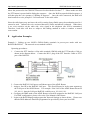
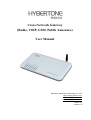
Cross-Network Gateway
(Radio, VOIP, GSM, Public Announce)
User Manual
Shenzhen HyberTone Technology Co.,Ltd.
Http://www.hybertone.com
[email protected]
[email protected]
2010-7-13
Version:1.0
http://www.hybertone.com
Content
1、
2、
3、
4、
5、
6、
7、
8、
9、
10、
11、
12、
13、
Important Notices
Gift Box Check List
Overview
Installation
Default Factory Settings
Web Configurations
Call Settings
Operating Instructions
Application Examples
Hardware Specifications
Software Specifications
Miscellaneous
Troubleshooting
ROIP302 Series User manual
http://www.hybertone.com
1
ROIP302 Series User manual
Important Notices
1、
This product is used to link up the civilian radio network, internet, and cellular phone
network.
Its operation and performance rely on the broadband network connections via
private and/or public networks and the cellular phone networks.
Due to the stability and
reliability of these networks, this product may not be able to link up all the networks
connected without any interruptions.
Therefore, it is not recommended to use this
product in an emergency system or a communication system with zero-failure.
2、
This product can bridge and extend radio networks all over the world.
Please consult
your local regulations in order to use this product legally.
3、
This product requires the use of dynamic DNS (DDNS) service.
For testing purpose,
this DDNS service is temporary provided for free by HyberTone Technology.
this service is not guaranteed without any interruptions.
However,
Customers are urged to build
their own DDNS server or obtain this service from a DDNS provider.
Free DDNS
server software may be obtained freely from your local network service provider.
4、
Customers and/or users are taking full responsibilities and all risks in using this product.
We are not responsible for any direct or indirect losses caused by, but not limited to,
communication failures as a result of product failure or network problems.
CUSTOMERS ARE ASSUMED TO HAVE READ AND ACCEPTED WITH FULL
UNDERSTANDINGS OF THE IMPORTANT NOTICES STATED ABOVE.
2
Gift Box Check List
Upon unpacking the gift box, please check carefully that all items listed below are included.
Please report to your supplier for any missing items immediately.
Item
Appearance
Description
http://www.hybertone.com
ROIP302 Series User manual
1.
1 x Main Unit
2.
1 x AC/DC Adapter
Input: 110/220VAC
Output: 12VDC, 2A
3.
3 x PTT Adapter Cables
4.
1 x Ethernet Cable
http://www.hybertone.com
3
ROIP302 Series User manual
Overview
The fundamental of RoIP(Radio over IP)technology is to convert the audio and PTT signals in a
radio terminal into IP packets and then transmit the data via the IP networks.
The challenge in this
technology is to insure that the audio is transmitted in real time and the PPT control signal is
transmitted immediately and reliably.
The radio range is general limited by the restricted
transmitting power, the antenna sensitivity, and other environmental factors.
The success
deployment of this technology extends the coverage of a radio network without using expensive
repeaters or links up multiple radio networks in the world.
In addition, this technology can also link
up the radio world to the VoIP world and the cellular world easily.
It truly makes voice
communications across multiple networks possible.
RoIP302 series is developed based on VoIP technology to realize RoIP functions in order to create
a new type of gateway to bridge voice communications across multiple networks (Radio, Cellular,
VoIP).
Its main advantages are low bandwidth usage, high fault tolerant, low loss in voice quality,
fast response, easy installation and configuration.
It is ideal for setting up a private network with
multiple voice communication platforms, a distributed network for remote management, a network
with extended coverage, and an integrated network of multiple amateur radio networks.
RoIP302 Series Cross-Network Gateway has 3 PTT interfaces.
Up to 3 audio channels from
radio networks can be connected to the RoIP302 simultaneously.
All 3 channels can be
programmed into the same or different groups in order to bridge real time voice communications to
various network interfaces.
RoIP302 Series has a built-in GSM / CDMA cellular phone module, user can access the radio
networks connected via the cellular network installed.
A radio terminal equipped with DTMF
generation capability can make an outgoing call via the cellular network as well.
This links up the
two networks which cannot be linked up via any traditional means.
RoIP302 Series gateway can also be a remote ON/OFF Switch.
relay to switch on or off the devices that are under control.
User can control the built-in
These devices could be an alarm signal,
a light, a public announce system, an electronic lock, etc.
RoIP302 Series gateway supports routing of IP voice stream to via a recording server.
Voice
records can then be saved to a hard disk and can be retrieved at any time for examinations.
RoIP302 Series gateway can be installed in IP networks with intranet or internet connections via
ADSL modem, Cable modem, or Local Area Network (LAN).
The unique built-in DDNS client
can help to simplify the installation and configuration without relying on a voice relay server in order
to achieve interconnections among RoIP302 Series gateways.
http://www.hybertone.com
3.1
ROIP302 Series User manual
Theory of Operation
The diagram below shows the concept of how RoIP bridge the voice communication two radio
terminals at two different locations. The PTT Interface Cable provided is used to connect
between the RoIP and the radio terminal. Please note how the signals are passing between these
two devices. The connection between the two RoIP302s is through internet or intranet. The
green lines actually show how the audio and the PTT control signals are transmitted between the
two radio terminals. The two RoIPs have created a virtual connection between the two radio
terminals.
3.2
Modes of Operation
With different options, RoIPs support both Point-to-Point Mode and Group Transmit Mode
operations. Please refer to Section 3.4 for more RoIP versions available.
There are two types of RoIPs: RoIP302 and RoIP302M. RoIP302s cannot only support
Point-to-Point operation. RoIP302M has a built-in SIP server for 12 clients (RoIP302 can only
support one client) and group transmit capability. The additional feature in RoIP302M is the
built-in SIP server and the ability to transmit voice signal a maximum of 12 SIP Clients
simultaneously.
1. Point-to-Point Mode
In this mode, one RoIP302 is using public IP and the others could use public IPs of private
IPs with DDNS enabled. If the built-in SIP server is used, either one of the RoIPs can be a
http://www.hybertone.com
master and the other will register to the master.
not have the same Group SIP Number.
ROIP302 Series User manual
Please make sure that both RoIP302s do
The diagram below demonstrates each RoIP302 are connected to 3 Radio Terminals. Each
terminal is assigned to a different group. The two RoIP are connected via a IP connection
as shown by the blue line. The PTT control signal is represented by the single purple lines
and the voice signals are represented by the double purple lines. When a voice
transmission is initiated from a channel, the RoIP302 will connect to the other RoIP302 in
order to establish a link with the corresponding channel automatically.
2. Group Transmit Mode
At least one RoIP302M is required to support the Group Transmit mode. This RoIP302M is
the master with its own unique Group SIP Number and offers its built-in SIP server for up to
12 RoIP302s (RoIP302M can also register as well for expansion) to register. The diagram
below shows only RoIP302s are used to register to the RoIP302M. Each RoIP302s must
have its unique Group SIP Number. A maximum of 12 RoIP302s can be deployed in this
example. Please note that only one one-way voice transmission is allowed at all time.
When a voice signal is transmitted from a RoIP302, RoIP302M will re-transmit the signal to
all other clients in the same group. If the voice signal is coming from a PTT port (radio
terminal) of the RoIP302M, the RoIP302M will re-transmit the voice signal to all other PTT
ports and SIP clients that are in the same group. For example, if Channel 802 talks, Channel
701, 803 and 804 can hear. If Channel 701 talks, Channel 802, 803, and 804 can hear.
http://www.hybertone.com
ROIP302 Series User manual
Please note that when more channels are used, the higher bandwidth is required and the poor
the performance of the system is. It is recommended that the user needs to insure sufficient
bandwidth is available and the network connection is stable before implementing a large
network. In general, intranet network is preferred in this case.
3.3
Application Examples
Application example 1: Link up radio network between two locations
- Using two RoIP302Gs to link up three radio channels in two different locations.
http://www.hybertone.com
ROIP302 Series User manual
Application example 2: Link up radio network at multiple locations
- As shown in the application diagram above, four locations can be linked up via one
RoIP302GM and three RoIP302G. The RoIP302GM has a built-in SIP server and the group
transmit capability to up to 12 SIP clients.
By replacing one RoIP302G with RoIP302GM,
the system is now in Group Transmit Mode and up to 11 more RoIP302Gs can be added to
the system.
Each RoIP302G now registers to the RoIP302M. This mechanism allows the
system to expand rapidly.
http://www.hybertone.com
3.4
4
ROIP302 Series User manual
Model Nomenclature
Installation
a) Back Panel
Label
1
Name
Switch
Description
Remote control: Relay switch with 220VAC input
and 500 mA load current.
2
3
4
Channel 3
Channel 2
Channel 1
5
Reset
Press 10 seconds to reset the device to factory
defaults.
6
WAN
7
8
LAN
Power
10/100Base-T WAN connection for external
access
10/100Base-T LAN connection
12V 1A
6-pin RJ11port for PTT Adapter Cable
6-pin RJ11port for PTT Adapter Cable
6-pin RJ11port for PTT Adapter Cable
http://www.hybertone.com
ROIP302 Series User manual
b) LED Indicators
LED Name
Power
RUN
Function
Power
RoIP Status
LAN
LAN port status
PC
PC port status
Channel 1
Channel 1
Tx/Rx status
Channel 2
Tx/Rx status
Channel 3
Tx/Rx status
GSM status
Channel 2
Channel 3
GSM
Description
Lights up when the power is connected.
Flashes every 250ms indicates the device is
not ready.
Flashes every 500ms indicates the device is
ready.
Lights up when the LAN port is connected.
Blinks when there are data transmissions.
Lights up when the PC port is connected.
Blinks when there are data transmissions.
Channel 1 is receiving / transmitting.
Channel 2 is receiving / transmitting.
Channel 3 is receiving / transmitting.
A GSM call is active.
c) Channel Port Pin Assignment
The channel port is a 6-pin RJ-11 Socket
1. PTTOUT
2. GND
3. Vin (Rx)
4. Aout (Tx)
5. GND
6. PTTIN
d)PTT Adapter Cable Wiring Diagram
http://www.hybertone.com
ROIP302 Series User manual
e) Switch Port
The built-in relay switch is connected to the middle two pins of
the RJ-11 socket. It acts as an ON/OFF switch for the external
system connected.
f) SIM Card Slot
The cell Phone SIM slot is located at the bottom of the device.
the bottom to access the SIM card holder.
upward.
Remove the plastic cover at
Slide the metal clip backward and the lift the clip
Please the SIM card properly with the cut corner pointing to the edge of the device.
Place the clip over the SIM card and then slide it forward to lock the clip.
g)Main Unit Setup
i. Connect the Switch Port to an external system for remote control. It can be used to switch on
and off a Public Announce (PA) system to instant broadcast. If the relay switch is
connected to high voltage load. The maximum rating for the internal relay is 240VAC and
500 mA load current.
ii. Connect the Channel Port to a Radio Channel via the PPT Adapter Cable provided. Up to 3
channels are supported.
http://www.hybertone.com
ROIP302 Series User manual
iii. Connect the WAN Port to a router, network switch, ADSL/Cable Modem for access an
external network or the public network.
iv. Connect the LAN Port to a local PC or a local Ethernet network (LAN). This allows sharing
the external network connected to the WAN Port with the local network. However, the
shared network is intended for configuration the device and is best not used for high data
traffics applications in order for the device to insure the best voice quality.
5
Factory Default Settings
The table below shows the factory default settings.
There are two ways to reset to the factory
default settings:
i.
Press the RESET switch for more than 15 seconds.
ii.
In the Configuration page, select Tools and then Reset Config.
Item
Login ID
Login Password
Factory Default Settings
admin
admin
WAN Port Setting
LAN Port Setting
PTT State
DHCP
192.168.8.1
“0” is active
GSM Login password
PTT maximum duration
Jitter Delay
123
60 seconds
60 milliseconds
Range
Programmable (16
characters in the ASCII
table)
“0” is active low
“1” is active high
8 digits or less
Less than 600 seconds
20 – 220 milliseconds
http://www.hybertone.com
6
ROIP302 Series User manual
Device Configuration Via Built-in Web Server
The built-in web server provides a comprehensive way to fully program the device manually.
6.1
Web Server Login
There are two methods to access the built-in web server.
Method 1 is to access the built-in web server via the LAN port.
Connect a computer to the
LAN port of the RoIP302 and configure its IP to 192.168.8.x (x = 2 to 254). Type the IP
address 192.168.8.1 in the address field of a web browser.
The following login window is then
-displayed.
Enter the User name and the Password now.
The user name for the administrative level is
“admin” and the default password is “admin”.
Please make sure to click on “Save Changes” after configuring the device.
Method 2 is to access the built-in web server via the WAN port. The WAN port is set to DHCP
mode as a default factory setting.
When it is first connected to a network with a DHCP host, it
obtains an IP address automatically from the host. In order to listen to the IP obtained, make a
call to the GSM SIM card number.
to ask for password.
Once the call is answered, the device plays a voice prompt
Dial “*00” and the device then reads out the WAN port IP address.
http://www.hybertone.com
ROIP302 Series User manual
Enter this IP in the address field of a web browser to get a login window as described in Method
1.
6.2
Status
This is the default page when you first login to the device web server.
It consists of three
columns and it is important to understand the information shown in this page in order to debug
or report a device problem.
1. Left hand column shows the device information and the SIP registration status.
2. Middle column shows information on the network configuration and its status.
3. Right hand column shows information on the GSM hardware, carrier and channel status.
http://www.hybertone.com
6.3
ROIP302 Series User manual
Configuration
The page contain all configuration settings for the RoIP.
sections/pages for the ease of configuration.
It is subdivided into various
The sub-pages include Preference, Network, Call
Settings, PTT Settings, GSM Settings, Recorder Settings, Broadcasting Settings, Group Codec
Settings, and Group Settings.
6.3.1 Preferences
The Preference page consists of the common settings for the device and is shown below.
The mains settings in this page include:
1. Language – This specifies the language for the webpage and the voice prompts.
Currently,
only English and Simplified Chinese are supported.
2. Time Zone and Time Server – Time Zone is specified as GMT + or – a fixed value.
RoIP
acquires the standard GMT time from the Time Server specified.
3. Auto Reboot – This option reboots the device automatically at the time specified.
4. DDNS – When the RoIP is installed in a network environment with dynamic IP and a SIP
server is not used, customer can choose to use our free DDNS service or DDNS offered by
other service provider.
Enable this option to connect to our DDNS service as shown above.
The current settings are set to connect to our DDNS server (hk.ippcn.com) using port
“39980” and the update time is 600 seconds.
Please note that the DDNS Address cannot
http://www.hybertone.com
ROIP302 Series User manual
be set to other DDNS server; this setting only works with our own DDNS server.
this service is used, the domain name for the RoIP is then <serial number>.com.
Once
The serial
number is shown on the bottom label.
5. Remote Control – This option allows a user to access the RoIP’s webpage directly from our
remote control server.
6.4
Network
Proper network environment is the key to insure the performance of the RoIP302. normal For
best performance, it is recommended to connect the RoIP302 to a network with a static IP.
general, this kind of network access offers higher bandwidth utilization.
In
The next preferred
network access method is ADSL / Cable modem with PPPoE dial up for dynamic IP allocation.
The worst is the sharing private network via a router.
on the bandwidth usage.
The performance of RoIP302 depends greatly
In this case, it is best to configure the router to DMZ mode to the IP of the
RoIP302.
In order to get network access, the LAN port must be configured according to the network
environment to be connected.
There are 3 access methods available for the LAN port configuration.
1. Static IP – This mode applies to both public and private IP network environment.
In the LAN
port configuration shown below, select “Static IP” and then fill in the parameters as provided by
your network administrator.
2. DHCP – When the RoIP302 is installed behind NAT and a DHCP host is available, select this
mode will enable the device to obtain LAN IP address and other network IPs automatically.
3. PPPoE – For most ADSL and Cable modem access method, the PPPoE dial up is normally used.
If the RoIP is connected directly to an access modem, you may need to select the PPPoE.
Please consult your ISP for further information if needed.
Fill in the User Name and Password
as provided by your ISP to complete this LAN port configuration.
http://www.hybertone.com
ROIP302 Series User manual
The PC Port allows other network devices to be attached to the GoIP4 Gateway. It offers both
Bridge and Static IP modes to meet your requirements. The factory preset is Static IP mode with
the IP address 192.168.8.1.
1)Bridge Mode
Select Bridge mode if your network topology requires the network devices (PC or others) to be
in the same network segment as the GoIP4 Gateway. In this case, the GoIP4 Gateway functions
as an Ethernet Switch.
2)Static IP Mode (Default Setting)
Select Static IP mode for a new network segment on PC port. In this case, the GoIP4 Gateway
functions as Router. Enter the IP address in IP Address field with a new segment address that is
different from that on the LAN port. Enter the subnet mask in Subnet Mask field accordingly.
A commonly used value is 255.255.255.0.
Enable the DHCP Server if you want the GoIP4 Gateway functions as a local DHCP host on PC
port. This will enables the GoIP4 Gateway to assign IP Addresses to network devices that are
attached to the PC port.
http://www.hybertone.com
ROIP302 Series User manual
Specify the Starting Address, Ending Address, and Static DNS accordingly.
6.5 Call Settings
The RoIP302 supports up to 3 groups with a unique Group SIP Number. Each RoIP302 must define
at least one group. The Group SIP Number is the only reference between a group and the PTT ports.
If the RoIP is connected to a SIP server, then this number is assigned by the SIP server administrator.
If a peer-to-peer configuration is used, then this number must be unique and is assigned by the user
arbitrary.
For SIP Proxy mode, each RoIP302 are designated as a terminal. The table below describes how to
program the key parameters. Other parameters should be programmed as required by the SIP
proxy.
SIP Proxy Mode Settings
RoIP302 Terminal
Group SIP Number
Assigned by the SIP Proxy
administrator
SIP Proxy
SIP Proxy IP or domain name
Auto Dial Number
The Group SIP Number of the
RoIP for voice connection to be
established when a PPT signal
defined in the PPT Setting is
active.
http://www.hybertone.com
ROIP302 Series User manual
For peer-to-peer mode, only two RoIP302s are used for interconnection. One RoIP302 is defined as
a Host which supports a proxy mode for other RoIP302 (referenced as terminal) to register. The
table below describes how to program the key parameters.
Group SIP Number
SIP Proxy
Auto Dial Number
Peer-to-Peer Mode Settings
RoIP302 Host
Unique number assigned by the
user
Host IP or DDNS if enabled
Blank
RoIP302 Terminal
Unique number assigned by the
user
Host IP or DDNS if enabled
The Group SIP Number of the
RoIP for voice connection to be
established when a PPT signal
is active as defined in Group
Settings (Section x.x).
The Auto Dial Number is basically the number that the RoIP302 automatically makes a call to when
a PPT signal is active as defined in the Group Settings (Section x.x).
6.6 PTT Settings
This section defines the PPT Signal settings. RoIP302 supports up to 3 PTT ports and each PPT
consists of two control signal (PTT Input and Output). Difference radio terminals may have
different requirement on the PTT control signals. Please consult the User Manual of your radio
terminal for more information.
1. Input Active Level defines the active level for the PTT Input. Select “1” if the PTT Input is
active when the electrical level is high (+5V). Select “0” if the PTT Input is active when the
electrical level is low (0V).
2. Output Active Level defines the active level for the PTT Output. Select “1” if the PTT Output is
active when the electrical level is high (+5V). Select “0” if the PTT Output is active when the
electrical level is low (0V).
3. PTT Output Expiry (s) defines the maximum duration in second for the PTT Output to be active.
This means that the maximum transmit time for a voice channel is limited by the PTT Output
Expiry. This method is used to prevent a radio terminal to occupy the voice channel indefinitely.
The minimum value is 30.
http://www.hybertone.com
ROIP302 Series User manual
6.7 GSM Settings
The GSM settings in this section mainly define the password for incoming and outgoing GSM calls.
If it is left blank, then no password is required.
The voice activation detection settings are listed below.
feature yet.
This firmware version does not support this
6.8 Recording Settings
The recording settings define the address of the recording server for each group.
RoIP Voice Recording User Manual for more information.
Please refer to the
6.9 Public Announce (PA) Settings
The RoIP302 provides a relay switch to control a PA system. When the RoIP302 receives the PA
ON Password, it turns on the relay to activate the PA system. Audio is transmitted to the PA system
at this time. When the RoIP302 receives the PA OFF Password, it turns off the relay to deactivate
the PA system. The duration for the relay to be in the ON state is limited by the value set in the
parameter PA ON Expiry. This mechanism shuts down the PA System automatically. The PA
Control Group defines which group has the control over the relay switch. Only the radio terminals
in the group specified can broadcast to the PA System.
http://www.hybertone.com
6.10
ROIP302 Series User manual
Group Codec Setting
Voice codec is commonly used in voice over IP communications. It enables voice to be compressed
in order to save the transmission bandwidth. The higher the compression rate is, the low the
transmission bandwidth is required. However, the voice quality is degraded as the compression rate
goes higher. In general, a-law, µ-law, and G.729 are commonly used. The transmission rate of a
single voice channel is about 82Kbps for a-law or µ-law and about 26Kbps for G.729. However,
when a radio station is required to transmit voice data, only a-law or µ-law codec should be selected
for no loss in voice quality.
It is important to note that all users in the same group must use the same codec.
6.11
Group Settings
The Group Settings assigns the radio channels (3 PTT Ports) and the GSM channel to one of the
three groups available. Once a channel is assigned, it cannot be assigned to another group.
In the diagram below, all 4 channels are assigned to Group 1. This means that there are no channels
left for Group 2 and 3. In this case, RoIP302 can only support one group operation. However, for
RoIP302M/RoIP302GM , Group 2 and 3 can be used as a conference bridge for other RoIP302s.
Please note that the web interface does not check for duplicate selection among groups. Please
make sure that each PTT or GSM channel can only be assigned to a group no more than one time.
6.12
Save Changes
Press “Save Changes” on the left column to save all changes made.
you when you exit.
The web server will not remind
http://www.hybertone.com
6.13
ROIP302 Series User manual
Online Upgrade
The Online Upgrade selection is the first item in the Tools menu. Please check regularly with your
supplier or our website (www.hybertone.com) for the latest firmware release.
7
Initiating a Cellular Call
The model RoIPx02G and RoIPx02GM have built-in GSM module to enable voice communication
with the radio channels that belong to the same group. This means that a telephone user can dial in
to the RoIP to conduct a voice call with the radio channels. A radio terminal equipped with DTMF
capability can also dial out to the telephone network to conduct a voice call. The ability to
communicate with other voice networks makes the RoIP302 a truly “Cross-platform Gateway”.
Below are the procedures to initiate a voice call.
1. Initiate a call from the telephone network to the radio
Use a PSTN or Cellular phone to call the phone number of the SIM card that is installed on the
RoIP302. Once the RoIP302 answers the call, it generates a voice prompt to ask the caller to enter
the GSM IN Password (described in Section 7.7) and then press the “#” key. The default password
is “123”. Once the correct password is entered, RoIP302 generates double beeps as confirmation.
The caller can then hear the voice communications of the group that the GSM Channel is assigned to.
Please note that only one way voice communication is allowed. The caller should wait for a silent
period before enabling the voice channel to talk. To enable the voice transmission, the caller needs
to press the “*” key to enable the PPT control before talking. Once the caller completes the
conversation, he/she should press the “#” key to disable the PTT control in order to deactivate the
voice transmission. Therefore, the Radio party can talk back. This mechanism simulates the PTT
method used in Radio Communication.
Please note that when the “*” or “#” key is pressed, the caller should hear a confirmation tone
(double beeps). If the caller does not hear this tone, he/she should dial the digit again. The caller
can just hang up the phone to end the call.
2. Initiate a call from the radio to the telephone network
To initiate a call via the GSM channel, the radio user should press and hold the PTT button to
activate the transmission and the dial the following sequence.
<password> + “#” + <phone number> + “#”
http://www.hybertone.com
ROIP302 Series User manual
where the password is the GSM OUT Password as described in Section 7.7. Please make sure that
the PTT button is pressed while dialing the sequence. Once the RoIP accepts the dialed sequence, it
will then play the voice prompt of “Dialing in Progress”. Once the call is answered, the RoIP will
then broadcast a voice prompt of “Call connected” to the radio caller.
Since the called party may not know the call is coming from a Radio party, the mechanism used in 1
cannot be used. Instead, the voice activated detection (VAD) mechanism is adopted. When there
is no voice activities on the radio side, voice signal at the telephone side will be transmitted.
Therefore, both sides will have to adapt to this talking method in order to conduct a normal
conversation.
8
Application Examples
Example 1: Linking up two MOTO GM300 Radio terminals in peer-to-peer mode with two
RoIP302/RoIP302G. The network access method is ADSL.
Operating procedures:
1. Connect the PTT Interface of the radio terminal (GM300) with the PTT Interface Cable as
shown in the diagram below. Connect the RJ-11 plug of the PTT Interface Cable to PTT1
port of the RoIP302.
2. Connect the RoIP302 LAN port to an Ethernet port of the ADSL Router
3. Assign a fixed IP to the RoIP302 LAN port. This fixed IP must be in the same segment as
the LAN port of the ADSL Router. For example: if the LAN of the ADSL Router has an IP
192.168.1.1, then the LAN port RoIP302 could be set to 192.168.1.101.
4. Configure the DMZ mode of the ADSL Router to fixed IP assigned to the RoIP302 LAN port.
For DMZ configuration, please refer to the User Manual of the Router.
5. Login to the RoIP Webpage and program the Network Settings as shown below. Please note
that the DNS addresses should be programmed as provided by from your local ISP.
http://www.hybertone.com
ROIP302 Series User manual
6. Next go to the PTT Setting page and set both PTT Input and Output to active low as shown
below.
7. Assign the RoIP302 at Location A to be the master and a Group SIP Number as 101.
8. Go to the Preference Page and enable the DDNS feature. If the serial number of the
RoIP302 is RoIP30220100610005, then the DDNS settings are shown below.
9. Next go to Call Settings page and configure it as shown below.
10. Configure the Group Settings as shown below. Since the PTT Interface Cable is
connected to PTT1 port and there are no devices connected to PTT2 and PTT3 ports, only
PTT1 port is assigned to Group 1. Select the GSM channel as required. Please note that
http://www.hybertone.com
ROIP302 Series User manual
the RoIP302 at location B should have the same Group Settings as the one at location A.
This means that the PTT1 port is assigned to Group 1 for both RoIP302s.
11. The last thing to configure is the Codec Settings. Choose a-law or µ-law for best voice
performance.
Please make sure that both RoIP302s use the same codec.
12. Next configure the RoIP302 at location B. First, go to the Preference Page to enable the
DDNS feature. If the serial number of the RoIP302 is RoIP30220100610006, then the
DDNS settings are shown below.
13. Next configure the Call Settings page as shown below. Please note that it has a different
Group SIP Number as the one in location A. Please note that the SIP Proxy address is set
to the DDNS of the RoIP302 at location A. The Auto Dial Number is set to the Group
SIP Number of the one at location. This means that 102 calls 101 automatically
whenever the PTT control is active (transmitting voice from 102 to 101).
14. Please note that the Network Settings, Group Settings and Codec Settings should be similar
to those described for the RoIP302 at location A.
15. At last, the two RoIPs are setup and ready to use. Just push the PTT button at one radio
terminal, voice is transmitted to the other radio terminal automatically. If the volume
level is not correct, please tune the 2K Potentiometer that is located at the PTT Interface
http://www.hybertone.com
ROIP302 Series User manual
adapter cable.
Example 2: This example demonstrates how to use a RoIP302M in order to achieve voice
communications among multiple locations simultaneously.
Conditions:
1. One RoIP302M with a public IP for internet access. It acts as a host for other RoIP302s.
2. Multiple RoIP302s with dynamic IPs via ADSL routers for internet access.
3. One ICOM2720 as a radio station as a command center.
4. Multiple GM300 radio terminals as users
Setting up RoIP302M:
1. The hardware setup of GM300 is the same as the one shown in Example 1.
2. Connect the PTT Interface of the ICOMIC-2720 with the PTT Interface Cable supplied as
shown in the diagram below. Connect the RJ-11 plug of the PTT Interface Cable to PTT1
port of the RoIP302M.
3. Assuming the public IP for the RoIP302M is 202.96.123.123.
be configured as shown below.
4. The DDNS feature should be disabled.
5. A Group SIP Number should be assigned to the RoIP302M.
Call Settings should be configured as shown below.
Its Network Settings should
If 3001 is assigned, then the
http://www.hybertone.com
ROIP302 Series User manual
6. Since the QSL output of the ICOMIC-2720 is active high, then the PTT Settings should be
configured as shown below.
7. Since the RoIP302M needs to be connected with multiple RoIP302s, the voice codec G.729
should be selected in order to lower the network bandwidth requirement.
8. Up to 3 groups can be defined in the Group Settings. Each group consists of remote
RoIP302 clients (referred as Soft Lines here) and onboard channels (PTT1, PTT2, PTT3,
GSM). Similar to RoIP302, each onboard channel can only be assigned to one group.
RoIP302M can at the most accept up to 12 client registrations. This means that these 12
clients (Soft Lines) are split among the 3 groups. In the example below, 12 Soft Lines are
assigned to Group 1 and this means that there are no more lines available for group 2 and 3.
Setting up a RoIP302:
1. The connection of GM300 to RoIP302 is the same as the one shown in Example 1.
2. The Network Setting is the same as that shown in Example 1.
http://www.hybertone.com
ROIP302 Series User manual
3. The DDNS feature should be disabled.
4. In the router configuration, DMZ mode should be configured to IP address of the RoIP302.
5. The Call Settings should be configured according to the example shown below. The Group
SIP Number must be unique for each RoIP302. The SIP Proxy should be set to the IP of the
RoIP302M. The Auto Dial Number should be set to the Group SIP Number of the
RoIP302M. This is the number to be called when the GM300 Radio is talking.
6. The Group Codec Setting must be set to G.729.
7. Repeat the above with other RoIP302s and a RoIP network with a maximum of 13 locations
can now be achieved.
8. If more locations are needed, it is possible to connect another RoIP302M to the master
RoIP302M. Then more RoIP302s can then be connected to the second RoIP302M. This
feature enables a much bigger and more flexible system to be built. The diagram below
demonstrates the concept of building such system.
9.
http://www.hybertone.com
9
ROIP302 Series User manual
Hardware Specifications
1 Physical and Operating Conditions
- Dimension: 25 x 14 x 3 cm
- Main Unit Net Wegith: 380 g
- Storage Temperature: -40°C - 80°C
- Operating Temperature: 0°C - 40°C
2 Core Design
- CPU: ARM9
- RAM: 16MB
- FLASH: 4MB
- DSP: 116 MHz, 16 Bit Bus
3 PTT Interface
- PTTIN Active Low: <0.7V (4.7KΩ load)
- PTTIN Active High: >1.2V
- PTTOUT High Output: 5V (4.7 KΩ load)
- PTTOUT Low Output: 0V
- APUT Output: 8Ω 750mW 5V P-P
- AIN Input: 600Ω Internal Impedance, 0 – 0.6Vp-t-p
- ADJOUT (on the Adapter Cable): 2KΩ Potentiometer
- RAM: 16MB
PTTIN Circuit:
* Based on the circuit above, the PPT Input level is high when it is open
ended.
http://www.hybertone.com
ROIP302 Series User manual
PTTOUT Circuit:
4 GSM Module
- Operating Frequencies: EGSM900MHZ/DCS1800MHz and GSM850MHz/PCS1900MHz
- Suported SIM Card: 3V SIM
- Transmit Power: Class 4 (2W) at EGSM900. Class (1W) at DCS1800 and PCS1900
5 Network Port
- Ethernet Port: 10/100 Base-T
- Standard Supported; IEEE802.1p
- IP Standard: IPV4
6 Firmware
Item
OS
IP Voice Protocol
Network Protocol
Codecs
Configuration GUI
Description
Remark
Linux
Version 2.6
SIP 2.0
Include SIP INFO extension
IP、TCP、UDP、HTTP、ICMP、DHCP CL & SRV、NTP、
TFTP、ToS、telnet
G.711 a&μ G.729A G.729AB G.723.1 GSM
Html XML2.0 JAVA