1
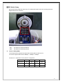
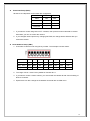
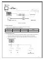
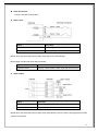
PTZOD Series 27X& 37XOutdoor PTZ 960H Module / 700 Line Resolution Version 1.0 NTH-PTZOD27X / NTH-PTZOD37X Please read this operation manual carefully before installing and using this unit CAUTl0N RISK OF ELECTRIC SHOCK DO NOT OPEN CAUTION:To reduce the risk of electrical shock, do not open covers. No user serviceable parts inside. Refer servicing to qualified service personal. This lightning flash with arrowhead symbol is intended to alert the user to the presence of un-insulated "dangerous voltage" within the product's enclosure that may be of sufficient magnitude to constitute a risk of electric shock to persons. This exclamation point symbol is intended to alert the user to the presence of important operating and maintenance (servicing) instructions in the literature accompanying the appliance. WARNING:To prevent the risk of fire or electric shock hazard do not expose Internal components of this camera to rain or moisture. 1 ▌▌Important Safeguard 1. Read Instructions Read all of the safety and operating instructions before using the product. 2. Retain Instructions Save these instructions for future reference. 3. Attachments/Accessories Do not use attachments or accessories unless recommended by the manufacturer as they may cause hazards, damage to the product and void warranty. 4. Water and Moisture Do not expose internal components to water or moisture. 5. Installation Do not place or mount this product in or on an unstable or improperly supported location. Improperly installed product may fall, causing serious injury to persons and damage to the product. Use only with a mounting device recommended by the manufacturer, or sold with the product. To insure proper mounting, follow the manufacturer’s instructions and use only mounting accessories recommended by manufacturer. 6. Power source This product should be operated only from the type of power source indicated on the label. ▌▌Precautions Operating Before using, make sure power supply and others are properly connected. While operating, if any abnormal condition or malfunction is observed stop using the camera immediately and contact a qualified technician. Handling Do not disassemble or tamper with parts inside the camera. Do not drop or subject the camera to shock and/ or vibration as this can damage the camera. Care must be taken when you clean the clear dome cover. Scratches and dust will ruin your quality of your picture. Installation and Storage Do not install the camera in areas of extreme temperature, which exceed the allowable range. Avoid installing in humid or dusty places. Avoid installing in places where radiation is present. Avoid installing in places where there are strong magnetic fields and electric signals. Avoid installing in places where the camera would be subject to strong vibrations. Never expose internal components of the camera to rain and water. 2 1. Introduction 2. Installation Guide Features Product and Accessories 4 8 Preparations 9 Installation Method 10 Installation Dimensions 11 3. Dome Setting DIP Switch Setup Cabling Check Points Before Operation Reserved Preset OSD Menu Functions 13 15 17 18 20 4. How to use OSD Menu Language System Information Display Setup Dome Settings Camera Motion Restart Factory Default 22 22 23 24 35 40 47 48 5. Specifications Specifications 49 Optional Bracket 51 3 █▐ Features ▌█ ▌▌Camera Specifications CCD Sensor: 1 / 4 " Interline Transfer CCD Camera Support: SCM-2273 (SAMSUNG) Zoom Magnification: x 27 Optical Zoom, x 16 Digital Zoom Camera Support: SCM-2373 (SAMSUNG) Zoom Magnification: x 37 Optical Zoom, x 16 Digital Zoom Day & Night Function Various Focus Mode: Auto-Focus / Manual Focus / Semi-Auto Focus. Independent and Simultaneous Camera Characteristic Setup in Preset operation ▌▌Main Features Step less speed changes, auto zoom/speed matching Pan 0.01~600o/S, Tilt 0.01o~120o/S Timing actions for 7 days of programmable schedule Built-in Semi-conductor heater & digital temperature sensor PWM cooling fan vari-speed temperature control Pan Tilt accuracy +/- 0.01o, 256 preset positions 8 cruising tracks, each cruising track has 32 presets 4 pattern tours,600sec memory, 500 programmable instructions Multi-Protocol through RS485 or coaxial cable. 8 auto scan with use-defined left and right boundaries and settable scan speed 4 Privacy Zones with defined English camera title Auto Compatible PELCO_P, PELCO_D compatible Guard Location: dome will rotate back to preset position after a period of idle time Alarm triggering: the alarm can trigger preset, auto scan, cruising and pattern tours functions Soft Address Function: the use can set up the dome address without uninstalling the dome ▌▌Integrated Super Speed PTZ Rotator Delicate stepping motor, stable, sensitive and accurate 360° Pan and 90° Tilt range (auto-flip) without blind area Stepless speed change, auto zoom/speed matching ▌▌All-weather Outdoor Design High die-cast alloy aluminum construction High Precision Mould with low heat conductivity 4 Fully enclosed isolation design for heat sink Nanometer Dustproof, waterproof and fog-proof lens IP66 Weatherproof 3000V lightning and surge current protection ▌▌Function Instructions Focus / PTZ Speed Auto Match The pan/tilt rotation speed is adjusted automatically according to the zoom in/out speed, which makes it much more practical for manual target tracking. (Only for the auto tracking IR speed dome) Power Up Action This function resumes the last action executed before power down. Most of actions such as Preset, Pattern, Swing and Group are available for this function. Auto Flip When the camera tilts downward and goes just beyond the vertical position, the camera will rotate 180 degrees to provide a correctly oriented picture. Preset Position Set up and Call Up In the Preset function the dome stores the current pan/tilt angle, zoom and other position parameters in its memory. When necessary the dome recalls these parameters and adjusts the camera to a particular position. The user can store, recall and clear the presets easily and promptly by using the keyboard controller. The dome can store up to 220 presets. Auto Scan Users can set up the left and right boundaries by control keyboard. Then speed dome can scan between these boundaries and supports up to 8 groups of scanning paths. Cruising Track The preset position can be programmed to be recalled in a set of sequences. This sequence can be set to let the camera scan from one position to the next in a cycle at a set speed. This feature is called the “auto cruise”. The cruise sequence and dwell time of each preset can be set. It supports up to 8 cruising tracks, each cruising track with 32 presets. Pattern Tour Dome can memorize 600s running paths or 500 programmable instructions. When starting the pattern tour, speed dome will move automatically according the recorded action path. It supports 4 groups of pattern tours. 5 Guard Location The dome will automatically return to a preset position if there is no operation over a period of time. Default Action When you start up the dome camera or the camera does not receive commands over a long period of time it will return to default functions which includes the home place, auto pan, auto cruise and pattern. Dome Address Setup The dome supports up to 256 addresses and the dome will only respond to the instructions given to its own address. Please check the dip switch on the dome for address setup. Manual Object Tracking The use can move the joystick up, down, left or right to track the object in the screen and use the joystick to zoom in and out with auto focus. Privacy Mask Protection Set black mask areas to protect the privacy zones. The black privacy locations can be set, and support up to 4 mask zones. Timing Running Function Users can set speed dome operation tasks at total 8 timing areas during 7 days. Coordinates and Directions Display User can define the dome’s direction of due north, which will help to show the exact moving directions on screen. Zone title is also supported and will display when the dome moves to the specified zone. Motion Detection The dome will detect the changes in the defined video zone and trigger alarm. It supports to 8 video Locations, each with 4 detection zones. PTZ and Lens Control Zoom Control Users can control zoom by keyboard to get near or far images. Focus Control The default setting is auto focus. The camera will auto focus based on the center of the video display to achieve a clear image. 6 Auto Iris Control Auto Iris detects the environmental lighting condition and adjusts the iris to get the correct brightness of the image. Auto Back Light Compensation In a highly bright background situation, auto back light compensation function compensates for the brightness of the dark object and adjust the background brightness to get a clear image. Auto/Manual White Balance Auto/Manual WB adjusts depending on the environment light changes. Day and Night Switch Speed dome can automatically switch according to the environmental illumination changes. OSD Setup (Only for camera with menu) Call upon preset No.95 to enter into OSD menu setup interface. Press “Focus” to choose menu items and press “Iris” to set menu contents. Information such as Camera ID, temperature, Pan/Tilt Angle, Alarm Input and Preset can be displayed on screen. I/O Functions (for Advance Type) Alarm sensor Input is decoupled with photo coupler. Using the dry contact for alarm input and output, if an external sensor is activated, camera can be set to move to the corresponding Preset position. Reserved Presets for Special Purpose Most camera characteristics can be set up easily and directly with reserved preset, not entering into OSD menu. For more information, refer to “Reserved Preset” in this manual. 7 ▌▌Product & Accessories NTH-PTZOD27X / NTH-PTZOD37X Accessories: User’s Manual Gloves,Screwdriver & Allen Wrench Anti-drop Rope AC24V/2A Power Supply 8 █▐ Installation Guide ▌█ ▌▌Preparations Basic Requirements All the electric work must be finished under the latest electric & fire prevention law and rules (and any related law and rules). Please check the packing list and verify every accessory is included. Please contact us for any help during the installation. Installation Space Checkup Please make sure there is adequate space for installing this dome. Be sure the mounting site material is sufficient enough and will hold the total weight of the dome and its accessories. Cable Preparation Please choose the proper cable according to the transmission distance. The minimum requirement of coaxial BNC cable is listed as follows for reference: Models Max Distance(Feet\Meter) RG59/U 750ft(229m) RG61/U 1,000ft(305m) RG11/U 1,500ft(457m) Setup for Dome Address The domes address and baud rate can be set up using two methods: “Traditional Dipswitch Method” and via the “Soft Address Method” which utilizes the OSD to set up the dome address and baud rates. Dipswitch Settings: To set up the dome using Dipswitches you will first need to remove the plastic shroud around the PTZ module. There are 4 screws which hold this shroud in place. It is recommended to set the dipswitches prior to installing the dome. *See pages 12-14 for further dipswitch setup instructions. Soft Address: The soft address method also can be used to set the dome address and baud rate without using the dipswitches. This method can be used after the dome has been installed. This feature is very useful when needing to change address or baud rates after the dome has been installed. ※ See page 30 for further soft address setup instructions. 9 ▌▌Installation Method Wall Mount Pendant Mount Drill Drawing: Drill Drawing: 10 ▌▌Installation Dimensions Wall-mount Installation Procedures: 1). Remove the bracket from the package and mark the installation holes position on the wall. . 2). Drill the hole and install the supplied 4x M8 expansion bolts into the hole. Pendant-mount Installation Procedures: PTZPEND237X bracket sold separately. *Notice: Pendant-bracket is not designed for outdoor installation. If installed outside please make sure the installation is water proof by using pipe thread tape and/or silicon. 1) Take out the bracket from the package, mark the installation holes position on the ceiling referencing to the bottom of bracket. 11 2) Drill the hole and install 4x of M8 expansion bolt into the hole. *Notice: The wall and ceiling must be thick enough to install the expansion and can bear 4 times the weight of the dome camera itself. █▐ Dome Setup ▌█ Before the dome is installed, please finish setting up the communication protocol, baud rate and dome address. To do this you will need to first remove the 4 screws in the plastic shroud to access the dipswitch settings. 12 ▌▌DIP Switch Setup Set the DIP switch inside the dome body. The relative DIP switch site and connecting wires are diagramed below for reference. SW1 — Dip switch for the dome address SW2 — Dip switch for the dome protocol Protocol Setup (SW2) Our IR speed dome supports two protocols including Pelco P and Pelco D. All of them supports baud rate of 9600bps、4800bps、2400bps. Set the No.1~4 dip switch for the protocol configuration. Protocol SW2-1 SW2-2 SW2-3 SW2-4 PELCO-P ON OFF OFF OFF PELCO-D OFF ON OFF OFF Reserved … … … … 13 Baud Rate Setup (SW2) Set the No.5~6 dip switch for the baud rate configuration. Baud Rate SW2-5 SW2-6 9600 OFF OFF 4800 ON OFF 2400 OFF ON Reserved … … 1. If you want to control using DVR or P/T controller, their protocol must be identical to camera. Otherwise, you can not control the camera. 2. If you changed camera protocol by changing DIP S/W, the change will be effective after you reboot the camera. Dome Address Setup (SW1) 1. ID number of camera is set using binary number. The example is shown bellow. PIN 1 2 3 4 5 6 7 8 ID Value 1 2 4 8 16 32 64 128 ID=5 ON OFF ON OFF OFF OFF OFF OFF Ex) ID=10 OFF ON OFF ON OFF OFF OFF OFF Ex) 2. The range of ID is 1~255. Factory default of Camera ID is 1. 3. If you want to control a certain camera, you must match the camera ID with Cam ID setting of DVR or Controller. 4. Speed dome can also change the ID address and baud rate via OSD menu. 14 ▌▌Cabling Cabling Terminal Block Power Connection Please, check the voltage and current capacity of rated power carefully. Rated power is indicated in the back of main unit. Rated Power Input Voltage Range Current Consumption Model AC24V AC24±2V 2A PTZOD27X / PTZOD37X RS-485 Communication 1. For PTZ control, connect this line to keyboard and DVR. To control multiple cameras at the same time, RS-485 communication lines are connected in parallel as shown below. 2. Speed Dome OSD Menu, support the distal 120R resistance of the opening and closing. 15 Video Connection Connect with BNC coaxial cable. Alarm input Signal Description IN COM Common point for alarm IN1-,IN2-,IN3-, IN4-,IN5,IN6,IN7 Alarm input signal Speed dome can detect the status of alarm input (NO or NC) automatically. Normal Open and Normal Close define as below: Normal Open No contact between alarm input and common point Normal Close Keeping contact between alarm input and common point Alarm output Signal Description Alarm output 1 Alarm output port 1 Alarm output 2 Alarm output port 2 Speed dome can detect the status of alarm input automatically; when any alarm was triggered then alarm output must be action. 16 ▌▌Check points before operation Before power is applied, please check the cables carefully. The camera ID of the controller must be identical to that of the target camera. The camera ID can be checked by reading DIP switch of the camera. If your controller supports multi-protocols, the protocol must be changed to match to that of the camera. If you changed camera protocol by changing DIP switch, the change will be effective after you reboot the camera. Since the operation method can be different for each controller available, refer to the manual for your controller if camera can not be controlled properly. The operation of this manual is based on the standard Pelco® Controller. ▌▌Preset and pattern Function Pre-Check Check how to operate preset and pattern function with controller or DVR in advance to operate camera function fully when using controller or DVR. Refer to the following table when using standard Pelco® D protocol controller. <Go Preset> Press [Call] input [Preset number]and press [Enter] <Set Preset> Press [Preset] input [Preset number] and press [Enter] <Run Pattern> Press [Call] input [Pattern number] and press [Enter] <Set Pattern> Please refer to the pattern setup, turn to “Pattern Setup” If controller or DVR has no pattern button or function, use shortcut keys with preset numbers. For more information, refer to “Reserved Preset” in this manual. ▌▌Starting OSD Menu Function Using the OSD menu, Preset, Pattern, Swing, Group Pan, Tilt and Alarm Input function can be configured for each application. Enter Menu Press <Call> + Preset Number [95] +<Enter> (or call preset No.1 two times continuously within two seconds) Move/ Select Item Control the joystick to move the cursor around the menu(Move the joystick up and down to select the item Enter Item Press “Iris Open” to enter the menu for selections (Press “Iris Open” to confirm the selection) Quit from Menu Press “Iris Close” to cancel the selection *Note: If your controller does not have a joystick, use the up or down key. 17 ▌▌Reserved Preset Description Some Preset numbers are reserved to special functions. 1 <Call> [95]<Enter> Enters into OSD menu 2 <Call> [99]<Enter> Run Pan Scan 3 <Call> [98]<Enter> Run Cruise(SEQ) Default as Cruise(SEQ) 1 4 <Call> [97]<Enter> Run Pattern Default as Pattern 1 5 <Call> [96]<Enter> Stop / End of set 6 <Set> [93]<Enter> Set the Right boundary Default as scan 1 7 <Set> [92]<Enter> Set the Left boundary pp: speed value 1~30 8 <Set> [87]<Enter> + <Call>[pp]<Enter> Stop / End of setting 9 <Set> [84]<Enter> + Default as scan 1 pp: Preset,the max. 32 Set the preset of cruise <Call>[pp]<Enter> + …… presets 10 <Call>[96]<Enter> End the preset setting qq: dwell time:1-60S, 11 <Set> [83]<Enter> + <Call>[qq]<Enter> Set dwell time of cruising Default as cruise 1 12 <Set> [86]<Enter> Start the pattern setting 13 <Call>[96]<Enter> End the pattern setting Default as pattern 1 <Call>[80]<Enter> + 14 Start the qq scanning <Call>[pp]<Enter> + <Call>[99]<Enter> 15 <Call>[80]<Enter> + <Call>[pp]<Enter> + <Set>[93]<Enter> 16 <Call>[80]<Enter> + <Call>[pp]<Enter> + <Set>[87]<Enter>+ <Call>[qq]<Enter> 17 Set right boundary of the pp scanning pp: Scanning 1-8 qq: speed value:1-30 Set the speed value of scanning <Call>[80]<Enter> + Start the pp cruising <Call>[pp]<Enter> + <Call>[98]<Enter> pp: Cruise 1-8 18 <Call>[80]<Enter> + <Call>[pp]<Enter> Set the preset of the pp qq: Presets, the max.32 + <Set>[84]<Enter>+ <Call>[qq]<Enter> cruising. presets 19 <Call>[96]<Enter> End the pp cruise setting 20 <Call>[80]<Enter> + <Call>[pp]<Enter> Set dwell time of cruising n:Dwell time 1-60s + <Set>[83]<Enter>+ <Call>[n]<Enter> 18 21 <Call>[80]<Enter> + Start the pp pattern. <Call>[pp]<Enter> + <Call>[97]<Enter> 22 <Call>[80]<Enter> + Start setting of the pp <Call>[pp]<Enter> + <Set>[86]<Enter> pattern. <Call> [96]<Enter> End setting of the pp pp: Pattern 1-4 23 pattern. 24 <Call> [94]<Enter> Reset 25 <Call> [82]<Enter> Load Default 26 <Call> [94]<Enter> Reset 27 <Call> [71]<Enter> Start Wiper System Self-Testing The dome will do self-testing after power up, and system status will show “Normal” if system is running normally. If error happens, testing result will be shown in “○” or “X”. “○” means normal and “X” means error. Please check the according meaning as follows: Serial NO. 1 2 3 4 5 6 Meaning Dip Switch Temperature Sensor Storage Pan Tit Camera ▌▌General Rules of Key Operation for Menu The menu items surrounded with <> has a sub menu. For aIl menu levels, to enter the sub menu, press OPEN key or use joystick in the right. To go to up-one-level menu, press CLOSE key or use joystick in the left. To move from items to item in the menu, use joystick in the Up/Down. To change a value of an item, use Up/Down of the joystick in the controller. Press OPEN key or use joystick in the right to save values and Press CLOSE key or use joystick in the left to cancel Values. 19 ▌▌OSD MENU FUNCTIONS 20 ▌▌MAIN MENU Language Language selection System Information The user can check the dome system information as required. The system information includes: Dome ID, dome address, baud rate, protocol, temperature, voltage, alarm info, dome title, version, date, time, and temperature scale. Display Setup Display setup allows the user to define the way to display the dome titles on the monitor. Dome Settings Set all of the speed dome functions. Camera Set all of the camera functions. Motion Set the action of speed dome including “Preset”、”Scan”、”Cruise”…etc. Restart Reset Factory Defaults Load factory default. Help Description of the operation and functions. 21 ▌▌LANGUAGE The language for the on-screen menus is Selectable. To change the display language: Press Iris Open to enter selection. All on-screen menus are changed to the selected language. ▌▌SYSTEM INFORMATION The user can check the dome system information as required. The system information includes: Dome ID, dome address, baud rate, protocol, temperature, voltage, alarm info, dome title, version, date, time, and temperature scale. Use the following steps to display the System Information screens: 1. Use the joystick to position the cursor along the SYSTEM INFORMATION. 2. Press Iris Open. The SYSTEM INFORMATION screen opens. Note: Only the Temp scale can be adjusted between Celsius and Fahrenheit in this section. 22 ▌▌DISPLAY SETUP Display setup allows the user to define the way to display the dome titles on the monitor. The displayed titles are listed as follows: DOME TITLE Indicate dome PRESET Indicate the dwell time for preset title MOTION Indicate the dwell time for auto function titles (auto scan/auto cruise/pattern tour) ZONES Indicate the dwell time for zone titles DATE/TIME Display the current date and time PAN/TILT Time to display PTZ info and zoom info ALARM Time to display alarm in/out info PROMPT Display prompt info Two options for the Dome Title and Date/Time: OFF and ON Other setup selections include: OFF Title will not be displayed when activated. ON Title will be continuously displayed when activated. 2 SEC Title will be displayed for 2 seconds after activation. 5 SEC Title will be displayed for 5 seconds after activation. 10 SEC Title will be displayed for 5 seconds after activation. Move the cursor by joystick to the desired setting, and press Iris Open to open the item. Move the joystick select the status and press Iris Open to confirm. Titles can be placed anywhere on the monitor. This feature allows you to customize the window of your monitor screen. To set a title position: 1. Use the joystick to position the cursor in the DISPLAY POSITION 2. Press Iris Open. 3. Use the joystick to move the title up, down, left, or right. 4. Press Iris Open. 5. Repeat steps 1 through 4 to position other titles 6. Position the cursor at BACK or EXIT. Press Iris Open to save settings and exit menu. 23 ente ▌▌Dome Settings IDLE setting means if there is no command for the dome for a period of time, the dome will run the actions as defined. 1. TIME: Move the cursor to “TIME” and press IRIS OPEN to enter, and move the joystick up and dome to select among 30 sec, 1 min, 5 min, 10 min and 30 min. And press IRIS OPEN to confirm. 2. ACTION: Move the cursor to “ACTION” and press IRIS OPEN to enter. Move the joystick to select the actions including” NONE, PRESET, SCAN, SEQUENCE, PATTERN. Press IRIS OPEN to confirm. 24 ▌▌ALARM The dome system has 7 alarm inputs and 2 alarm output. When an alarm is received, an input signal to the dome triggers the user defined action (such as presets, patterns, etc.), and at meantime the alarm output signals is activated. 1. ALARM NO.: Move the cursor to the ALARM NO. Press IRIS OPEN to enter and move the joystick up and down to select the alarm input no. (Channel 1 and Channel 2) 2. CONTACT: Set the alarm contact status. There are two input states, OPEN and CLOSE. N/O normally open N/C normally close 3. ALARM MODE OFF Alarm function is deactivated. ON Alarm function is activated. AUTO AUTO Alarm function will be activated and deactivated between START TIME and STOP TIME. 4. ACTION: Set the alarm action: NONE (default) No action. PRESET Dome goes to preset. SCAN Dome starts auto scan SEQ Dome runs auto cruise PATTERN Dome runs pattern 5. ALARM OUT: Set the auxiliary to activate: OFF Not alarm output will be activated. OUT1 An alarm action will close AUX 1 output. OUT2 An alarm action will activate AUX2 output. ALL 6. RESET DELAY: Set up time for the alarm output (such as an alarm buzzed) when is triggered by the detector. 10 sec., 30 sec., 1 min., 2 min., 5 min., 10 min. 7. START /STOP TIME: Set up the time to start alarm and stop alarm ONLY under the AUTO mode under ALARM MODE. 25 ▌▌PRIVACY MASK Privacy mask allows the user to mask the privacy areas with black frame. The user can set up a maximum of 4 privacy masks. 1. MASK NO.: Move the cursor here and press IRIS OPEN to enter the setup of Mask Number of the privacy zone, 2. ENABLE: To enable or disable this privacy mask function. 3. SET: Move the cursor here and press IRIS OPEN to enter the mode of setting the privacy mask. Move the joystick (Left/Right/Up/Down) on the screen to set up the privacy zone and press IRIS OPEN to confirm. 4. DELETE: Move the cursor here and press IRIS OPEN to delete the current No. of privacy mask zone. 26 ▌▌DATE/TIME The dome can display the data and time. And the user could enter this CLOCK menu to set up the DATE and TIME. 1. DATE: Move the cursor here and press IRIS OPEN to enter. Move the joystick left and right to choose the date position and move it up and dome to adjust the figures. Press IRIS OPEN to confirm. 2. TIME: Move the cursor here and press IRIS OPEN to enter. Move the joystick left and right to choose the time position and move it up and dome to adjust the figures. Press IRIS OPEN to confirm. 3. CALIBRATION: To adjust the time if it is too fast or slow. Ex: If the displayed time is 5 seconds faster after 30 days then decrease the calibration value by 5. 4. SAVE/CANCEL: Move the cursor to “SAVE” and press IRIS OPEN to save the settings. Move the cursor to “DELETE” and press IRIS OPEN to cancel the settings. 27 ▌▌PASSWORD The dome features a password protection function to prevent unauthorized changes to the dome settings. If the PASSWORD function is enabled, the operator can not access any dome setting without entering a valid password. 1. EDIT PASSWORD: Move the cursor here and press IRIS OPEN to enter. Please enter the old password before set up the new password. The initial password is “111111” 2. ENABLE: Move the cursor here and press IRIS OPEN to enter. Move the joystick to select between “ON” and “OFF” . The user need to enter the password when opening the OSD under the status of “ENABLE: ON”. NOTE: It is strongly recommended to remember or securely store the new password if password protection is enabled. In the event the user forgets their password the dome will need to be defaulted to regain control. A keyboard can be used to get default the camera (call+82+enter) – this will default all dome settings. 28 ▌▌DOME TITLE The user can set up the dome title to define each camera. Dome title support up to 12 characters Move the cursor according the left steps and select INPUT. Press IRIS OPEN to enter. 1. Move the joystick left and right to position “←”, and press IRIS OPEN to delete the character at“←”. Press IRIS CLOSE to exit the edit mode. 2. Move the cursor to “<CAP>” and press IRIS OPEN to enter. Move the joystick up and down to select the input method (such as English Cap, English, Chinese, Figures, and Symbols) 3. Mover the cursor to next line of <CAP> and press IRIS OPEN to enter the mode of character input. The selected character will be shown in high brightness. Move the joystick up/down/left/right to choose the needed characters. Press IRIS OPEN to move the selected character to the INPUT position at“←”. 4. After finishing the character inputs, move the cursor to “OK” and press IRIS OPEN to confirm. 5. Also user can move the cursor to “CANCEL” to cancel the character input settings. 29 ▌▌SOFT ADDRESS SET The use can set up the SOFT ADDRESS, SOFT PROTOCOL and SOFT BAUD RATE under this menu here to activate the soft address function. And then the defined dome address by dip switch will be disabled. 1. Move the cursor to INPUT (under DOME ID) and press IRIS OPEN to enter the mode of setting dome ID, Move the joystick to position the cursor beside :0 1 2 3 4 5 6 7 8 9” and press IRIS OPEN to enter. And move the joystick again to select numbers of dome ID and press IRIS OPEN to confirm. The number selected will be input on the upper line. 2. Move the cursor to INPUT (the bottom menu) and press IRIS OPEN to enter the mode of setting soft address, Move the joystick to position the cursor beside :0 1 2 3 4 5 6 7 8 9” and press IRIS OPEN to enter. And move the joystick again to select numbers of dome soft address and press IRIS OPEN to confirm. The number selected will be input on the upper line. 3. Enable or disable the soft address function. Press IRIS CLOSE to exit last step. Move the cursor to “SOFTADDRESS:ON/OFF”. Press iris open to enter. Move the joystick up or down to select ON of OFF. Press IRIS OPEN to confirm. 4. Press OK to save and confirm all the settings and press CANCEL to exit all the settings. 30 ▌▌AUX The user can set up the auxiliary output to trigger other devices from an alarm or a controller. Move the cursor to AUX and press IRIS OPEN to enter to select “ON” or “OFF” to enable or disable this function. 31 ▌▌SOFT LIMIT The user can set up the soft limit to define the left and right boundaries for the pan movement. SOFT LIMIT: Move the cursor here and press IRIS OPEN to enter. Move the joystick to select “ON” or “OFF” to enable or disable this function. 1. LEFT LIMIT: Move the cursor here and press IRIS OPEN to enter. Now the user can mover the joystick to control the PAN movement of the dome to a defined position for the left limit. Press IRIS OPEN to confirm. 2. RIGHT LIMIT: Move the cursor here and press IRIS OPEN to enter. Now the user can mover the joystick to control the PAN movement of the dome to a defined position for the right limit. Press IRIS OPEN to confirm. 3. LIMIT DELETE: Move the cursor here and press IRIS OPEN to delete all the settings. 32 ▌▌DOME SPEED To make a selection of the dome speed, the user can enter this menu to set up. Move the cursor to DOME SPEED and press IRIS OPEN to enter. Move the joystick to select the dome speed when doing the pan movement. Move the cursor to BACK/EXIT and press IRIS OPEN to run the command of BACK or EXIT. 33 ▌▌POWER ON ACTION The user can define the dome action when power on, Move the cursor to POWER ON ACTION and press IRIS OPEN to enter the mode of setup. NONE (default) No action. PRESET Dome goes to preset. (Default as Preset 1) SCAN Dome starts auto scan (Default as Auto Scan 1) SEQ Dome runs auto cruise (Default as Auto Cruise 1) PATTERN Dome runs pattern (Default as Pattern 1) 34 ▌▌CAMERA The dome can automatically recognize the main camera modules in the market. For the cameras it can not recognize, the user can set up here. 1. CAMERA: Move the cursor here and press IRIS OPEN to enter the setup mode. Move the joystick up and down to select the camera types. Press IRIS OPEN to confirm. 2. BAUDRATE: Move the cursor here and press IRIS OPEN to enter the setup mode. Move the joystick up and down to select the baud rate. Press IRIS OPEN to confirm. 3. PARITY: Move the cursor here and press IRIS OPEN to enter the setup mode. Move the joystick up and down to select the parity mode. Press IRIS OPEN to confirm. 35 ▌▌COMMUNICATION TEST The dome can do self diagnosis for the communications between keyboard and speed dome. The test needs to match with our software VK200. If the self testing is successfully finished via the software, the system will show up the testing results as left diagram. TILE ANGLE : To set up TILT angle the maximum can be -10 degrees DOME VIDEO : To set up the Video System. 36 ▌▌OTHERS The user can set up TEMP MODE, INTERNAL FAN, PRESET FREEZE, STOP TIME, MENU OFF TIME and NORTH ZERO here under the “OTHERS” menu. 1. TEMP MODE: To set up the control mode of dome fans and heaters. It includes three modes of AUTO, FAN HIGH SPEED and FAN LOW SPEED. 2. PRESET FREEZE: This feature freezes the scene on the monitor when going to a preset. This allows smooth switching from one preset scene to another. 3. AUTO FLIP: When the camera tilts downward and goes just beyond the vertical position, the camera will rotate 180 degrees. The user can press IRIS OPEN to enter and choose to turn on/off this function. 4. STOP TIME: To set up the time that dome will stops after receiving the last command. Options include 5/15/30/60 Sec. 5. MENU OFF TIME: To set up the time that OSD menu be off when no operations. Options include 1/2/5/10 min. 6. AZIMUTH ZERO: (North Position) To set up the due north of the dome (pan 0º) Move the cursor here and press IRIS OPEN to enter. Move the joystick to control the dome to pan 0º and press IRIS OPEN to confirm. 37 ▌▌CAMERA SSDR (Wide Dynamic Range) Brightens darker areas of the image and darkens lighter areas of the image to even out the overall brightness of images with high contrast between bright and dark areas. 1. When the SETUP menu screen I displayed, select ‘SSDR’ by using the joystick so that the arrow indicates ‘SSDR “ON” then press the open key to get in the next setting. 2. Use the joystick to change the SSDR level according to the contrast between bright and dark area. WHITE BAL(White Balance) The white balance control modes are as follows: ATW(Auto Tracking White Balance): Select this when the color temperature is between 1800°K and 10500°K MANUAL: To fine adjust, select the Manual mode. You can increase or decrease the red or blue factor while monitoring the difference on the screen. Press OPEN button to 'MANUAL' mode and swing the joystick LEFT and RIGHT to Increase or decrease the value for red(R-Gain) and blue(B-Gain), watching the color of the picture, and select the RETURN then press OPEN button when you obtain the best color. AWC(Auto White balance Control): The white balance is automatically adjusted in a specific environment. In order to obtain the best result, while the camera focuses on white paper. If the environment including the light source is changed, you have to adjust the white balance again. OUTDOOR: This mode can be used within the color temperature range 1800~10500°K (Ex: fluorescent light, outdoor, sodium vapor lamp or inside tunnels) INDOOR : This mode can be used within the color temperature range 3000K~10500°K. BACKLIGHT When there is a strong backlight behind the object, clear images of the background as well as the object can still be obtained by using the BACKLIGHT function. 1. Position the arrow to point to 'BACKLIGHT' on the SETUP menu by using the joystick UP and DOWN . 38 2. Then select the mode you wish to operate by swing the joystick LEFT or RIGHT. OFF: BACKLIGHT function does not operate. BLC: Enables a user to select a desired area from a picture, and to view the area more clearly. HLC (High Light Compensation) : If the scene contains extremely bright light areas such as from car headlight, HLC can be used to mask out the bright areas of the picture. - LEVEL : Adjust level of the HLC function.(LOW,MIDDLE,HIGH) - MASK TONE : Change the brightness 3.Select a desired mode swing the joystick Left and Right and press the OPEN button. • Select ‘BLC’ to adjust the area to be enhanced then adjust the level. • HLC : Enable the user to change the level, mask tone area. MOTION DET (Motion Detection) OFF: MOTION DETECTION mode is cancelled. ON: Any motion in the selected areas is observed. AREA SEL: You can select the area you wish to observe from the 8 areas. AREA MODE: Determines whether to use the MD area selected in SENSITIVITY SENSITIVITY: You can select low or high level. When SENSITIVITY is high, motion detection sensitivity is increased to recognize even small movement. SMART ZOOM: Smart zoom is operated in connection with MOTION DETECTION. When the SMART ZOOM function is ‘ON’ while the MOTION DETECTION mode is ‘ON’, the zoom goes to the TARGET ZOOM position once motion is detected. Once the zoom action is finished and ‘DWELL TIME’ has passed, the zoom returns to the ‘START ZOOM’ position. -START ZOOM: By moving the left or right button in the ‘START ZOOM’ item to select the zoom position from 1x to 23x to be returned after the ‘SMART ZOOM’ action is over. -TARGET ZOOM: Use the left or right button in the ‘TARGET ZOOM’ item to select the zoom position from 1x to 23x to be used during MOTION DETECTION. - DWELL TIME : Use the left or right button in the ‘DWELL TIME’ item to select a time between 5 and 60 seconds for the dwell time before the zoom is returned to the ‘START ZOOM’ position. (5,7,10,15,20,30,40,60 sec) FOCUS 1. Access the main setup menu and then position the indicator over FOCUS using the UP or DOWN . 2. Swing the joystick LEFT or RIGHT or OPEN to confirm. MODE: You can select the most suitable zoom mode. Move the arrow indicator to ‘MODE’ using joystick UP or DOWN . AUTO: Select AUTO and press the SET button to confirm. Increase or decrease optical zoom (ZOOM) or digital zoom (D-ZOOM) positions using the UP or DOWN button while 39 verifying the changes on screen. Enabling D-ZOOM (ON) means that digital zoom will activate once optical zoom ends. The focus automatically adjusts when the lens zooms in and out. ONE PUSH: Focus is automatically adjusted just once, after zoom position is changed. Select ONE PUSH' and press the WIDE or TELE button to confirm. Increase or decrease optical zoom (ZOOM) or digital zoom (D-ZOOM) positions using the directional buttons while verifying the changes on screen. Press the WIDE or TELE button once desired image quality is obtained. MANUAL: Select 'MANUAL' and press the WIDE or TELE SET button To confirm. Increase or decrease optical zoom (ZOOM) or digital zoom (D-ZOOM) positions using the directional buttons while verifying the changes on screen. Press the WIDE or TELE button once desired image quality is obtained. Focus can be manually adjusted, independent of moving zoom. ZOOM TRK: Select ‘ON’ for the ‘SMART ZOOM’ item in the MOTION DETECTION menu and press SET button to change the settings for the ‘SMART ZOOM’ function. ZOOM SPEED: Configure zoom tracing speed using this feature. Position the indicator over 'ZOOM SPEED' using the UP or DOWN button and then set to desired mode using the joystick LEFT or RIGHT button. FAST: To move zoom fast. SLOW: To move zoom slowly. MEDIUM : To move zoom at medium speed. D-ZOOM: Configure magnification limit from x2~x16 using this feature. Position the indicator over 'D-ZOOM' using the UP or DOWN button. Set 'D-ZOOM' to 'ON' and press the WIDE or TELE button to confirm. Set 'ZOOM LIMIT' to the desired level using the LEFT or RIGHT button. ZOOM POS INIT: Moves to the controlled ZOOM position when the power turned on and is a function of the initial ZOOM position has been set. • AUTO : If you turn the power off and on, the zoom magnification level is set to the previous level that was set before the power went off. • MANUAL : The zoom magnification level can be set from 1x to 23X. USER PRESET: PRESET NO: Up to 128 preset configurations are supported. SAVE: Save configured preset. CLEAR: Clear configured preset. RETURN: Revert to the FOCUS SETUP menu. 40 LENS INIT: Use this feature to initialize the lens. Position the indicator over LENS INIT. using the UP or DOWN button. Press the OPEN button to confirm. - AUTO : The lens can automatically be set by a pre-selected day, from 1-day to 7-days. This will start from when the time is set. - Manual : The Lens will reset when you press the SET button. EXPOSURE 1. Access the main setup menu and then position the indicator over 'EXPOSURE' using the UP or DOWN button. 2. Press the OPEN button to confirm. BRIGHTNESS: Use this feature to adjust image brightness. Position the indicator over 'BRIGHTNESS' using the UP or DOWN button. Now increase or decrease brightness level using the joystick LEFT or RIGHT while verifying the changes on screen. Set END once desired level is obtained. IRIS: Set 'IRIS' to 'AUTO' or 'MANUAL'. Position the indicator over 'IRIS' using the UP or DOWN button and then select the desired iris mode using the LEFT or RIGHT button. AUTO: The iris is automatically activated upon illumination. MANUAL: Manual iris configuration. Set 'IRIS' to 'MANUAL' using the LEFT or RIGHT and then press the WIDE or TELE. Increase or decrease iris level using the LEFT or RIGHT button while verifying the changes on screen. SHUTTER: Control image brightness by adjusting shutter speed. 1. Position the indicator over 'SHUTTER' using the UP or DOWN button. Then select the desired shutter mode (A.FLK, ESC, MANUAL) using the LEFT or RIGHT button. 2. A.FLK (NTSC: 1/100, PAL: 1/120): Flicker-free mode ESC: Automatic shutter speed setting (optimal) MANUAL: Manual shutter speed setting If you choose ‘MANUAL’, select the optimal shutter speed. In MANUAL mode, the optimal shutter speed needs to be designated. Select from 1/60 to 1/120,000 (NTSC) or from 1/50 to 1/120,000 (PAL). * 'Sens-Up' mode can be configured manually (2x to 368x). 3. Verify changes made to the shutter speed by referencing to changes in on screen brightness. Press the WIDE or TELE button to complete. AGC (Auto Gain Control): For brighter images. 1. Position the indicator over 'AGC' using the UP or DOWN button. 2. Set 'AGC' to the desired mode using the LEFT or RIGHT button. HIGH: Wide range gain value adjustment 41 MANUAL: OFF: Disabled LOW: Narrow range gain value adjustment. MEDIUM: Medium range gain value adjustment. Select gain value range (5dB~41dB) SSNR3: On screen noise reduction. 1. Position the indicator over 'SSNR' using the UP or DOWN button. 2. Set 'SSNR' to the desired mode using the LEFT or RIGHT button. LOW: Low noise reduction MEDIUM: Medium noise reduction HIGH: High noise reduction OFF: Disabled SENS-UP: This feature ensures clear images at night or under low lighting conditions. 1. Position the indicator over 'SENS-UP' using the UP or DOWN button. 2. Set 'SENS-UP' to the desired mode using the LEFT or RIGHT button. AUTO: Select this mode for use in night time or under low lighting conditions. OFF: Disabled SPECIAL 1. Access the main setup menu and then position the indicator over 'SPECIAL' using the UP or DOWN button. 2. Press the OPEN button to confirm. DAY/NIGHT: You can display pictures in color or black and white. 1. When the SETUP menu screen is displayed, select ‘DAY/NIGHT’ using the UP or DOWN button so that the arrow indicates 'DAY/NIGHT'. 2. Select a desired mode using the LEFT or RIGHT button according to the picture display you want. - AUTO : The mode is switched to 'Color' in a normal environment, but switches to 'B/W' mode when ambient illumination is low. To set up the switching time or speed for AUTO mode, press the SET button. - COLOR : The picture is always displayed in color. - B/W : The picture is always displayed in black and white. • DWELL TIME : You can select day/night switching delay time from. → 5,7,10,15,20,30,40, 60(sec) • DURATION : You can select the day/night switching point(lux). COLOR → B/W B/W → COLOR FAST 2.6 Lux 4.2 Lux SLOW 1.2 Lux 6.0Lux * When AGC is middle mode. EXT : This mode allows you to apply a desired filter to external signals. 42 DIS: The DIS mode can compensate for vibration of the camera. SYNC: Internal synchronization CAUTION: Do not change camera’s Baud Rate and UART Mode or it will lose control. COMM ADJ: This function sets up the camera communication status when controlling the camera through an external controlled device. 1. When the SPECIAL menu screen is displayed, using the UP or DOWN button so that the arrow indicates ‘COMM ADJ’. 2. Set up the mode moving the 4 direction of the SET button. - BAUD RATE : You can select 2400/4800/9600/19200/38400/57600 bps. - UART MODE : You can select NONE, EVEN or ODD for the parity bits. -IMAGE ADJ: Includes image quality or special function factors. H-REV: Use this feature to horizontally inverse the screen. V-REV: Use this feature to vertically inverse the screen. SHARPNESS: Increasing this value sharpens object edges. Too high of a setting, however, produces noise and may obscure the image. MONITOR: Select from CRT, LCD, USER modes. - LCD : Please select this menu item when using an LCD monitor. - CRT : Please select this menu item when using a CRT monitor. - USER : Please use this menu item when using a monitor other than standard ones. You can change the gamma, PED level, and color gain in the sub menus. DISPLAY:. Use this feature to designate a name for the camera, which will display on the monitor screen. 1. To display the main setup menu and move the arrow indicator to 'CAM TITLE' using the UP or DOWN . 2. Set 'CAM TITLE' to 'ON' using the joystick LEFT or RIGHT. 3. Select the character by joystick.. 4. You can enter up to 15 characters. Move the cursor to the character entry field using the ← or →. Use joystick UP, DOWN, LEFT, and RIGHT to select a desired character. Press the OPEN button to confirm selection of the blinking character. The character is then saved, and the cursor in the entry field moves to the next position. Repeat steps through until the desired name has been entered. 43 1. Select on screen position of the CAM TITLE. Move the cursor to 'POS' by joystick. The CAM TITLE is displayed on the top-left of the monitor screen. (Default position) 2. When completed, move the cursor to 'END' and press OPEN button. RESET This function is used to reset your camera to the factory default condition. 44 ▌▌PRESET The dome supports 220 presets. Please check the following steps to set up a preset. 1. PRESET NO.: Move the cursor here and press IRIS OPEN to enter the setup of Preset Number. Move the joystick to select a preset number (1-64 and 100-255) and press IRIS OPEN to confirm. 2. TITLE: Move the cursor here and press IRIS OPEN to enter the setup of Preset Title. Check the detailed above in DOME TITLE settings. 3. <SET>: Move the cursor here and press IRIS OPEN to enter. Move the dome to a defined position as preset point and press IRIS OPEN to save the preset position. 4. CALL: Move the cursor here and press IRIS OPEN to call up the current preset. 5. DELETE: Move the cursor here and press IRIS OPEN to delete the current preset. 6. SPEED: Move the cursor here and press IRIS OPEN to set up the preset call up speed of LOW, MID and HIGH. 45 ▌▌SCAN The dome supports 8 groups of auto scan. Please check the following steps to set up a scan. 1. SCAN NO.: Move the cursor here and press IRIS OPEN to enter the setup of SCAN Number. Move the joystick to select a preset number (1-8) and press IRIS OPEN to confirm. 2. TITLE: Move the cursor here and press IRIS OPEN to enter the setup of SCAN Title. Check the detailed above in DOME TITLE settings. 3. START: Move the cursor here and press IRIS OPEN to start the current scan. 4. <LEFT LIMIT>: Move the cursor here and press IRIS OPEN to enter. Move the dome to a defined position as left limit and press IRIS OPEN to save this left boundary. 5. <RIGHT LIMIT>: Move the cursor here and press IRIS OPEN to enter. Move the dome to a defined position as right limit and press IRIS OPEN to save this right boundary. 6. SCAN SPEED: Move the cursor here and press IRIS OPEN to set up the scan speed ranging 1-30. 46 ▌▌AUTO CRUISE (SEQUENCE) The dome supports 8 groups of auto cruise and each cruise supports 32 presets. . Please check the following steps to set up cruise. 1. SEQ NO.: Move the cursor here and press IRIS OPEN to enter the setup of Sequence Number. Move the joystick to select a preset number (1-8) and press IRIS OPEN to confirm. 2. TITLE: Move the cursor here and press IRIS OPEN to enter the setup of Sequence Title. Check the detailed above in DOME TITLE Settings. 3. <SEQUENCE SET>: Move the cursor here and press IRIS OPEN to enter. Move the cursor to EDIT and press IRIS OPEN enter edit mode of sequence. Move the joystick left and right to select each item. When the < > is on the item NO., move joystick up or down to select the Serial NO. of the preset in a sequence. There are up to 32 presets in each sequence. When the < > is on the item PRESET, move the joystick up or down to select the preset NO. the user wants to add in the sequence. When the < > is on the INTERVAL, move the joystick up or down to select the interval time between each preset. When the < > is on the last item, move the joystick up or down to select edition mode as “INS (insert)”, “ok” and “delete”. Press IRIS OPEN when selecting INS to insert the settings into the position of current Serial No. Press IRIS OPEN when selecting OK to override the settings of Current Serial No. Press IRIS OPEN when selecting delete to delete the settings of the Current Serial No. Press IRIS OPEN to save all the setting and press IRIS CLOSE to exit. 4. DELETE/START: Move the cursor here and press IRIS OPEN to delete/start the current sequence. 47 ▌▌PATTERN The dome supports 4 pattern tours and each pattern cover at most 10 Minutes of 500 commands. Please check the following steps to set up a pattern. 1. PATTERN NO.: Move the cursor here and press IRIS OPEN to enter the setup of Pattern Number. Move the joystick to select a pattern number (14) and press IRIS OPEN to confirm. 2. TITLE: Move the cursor here and press IRIS OPEN to enter the setup of Pattern Title. Check the detailed above in DOME TITLE settings. 3. <SET>: Move the cursor here and press IRIS OPEN to enter. Move the dome up/down/left right, make the zoom in/out and press IRIS OPEN to save the pattern tour. 4. START: Move the cursor here and press IRIS OPEN to start the current pattern tour. 5. DELETE: Move the cursor here and press IRIS OPEN to delete the current pattern tour. 48 ▌▌ZONES The use can set up zone title when the camera moves to a defined location, which will make it much easier for the user to identify the location. The dome supports 8 zone titles. Please check the following steps to set up a zone 1. ZONE NO.: Move the cursor here and press IRIS OPEN to enter the setup of Zone Number. Move the joystick to select a zone number (1-8) and press IRIS OPEN to confirm. 2. TITLE: Move the cursor here and press IRIS OPEN to enter the setup of Zone Title. Check the detailed above in DOME TITLE settings. 3. <LEFT LIMIT>: Move the cursor here and press IRIS OPEN to enter. Move the dome to a defined position as left limit and press IRIS OPEN to save this left boundary. 4. <RIGHT LIMIT>: Move the cursor here and press IRIS OPEN to enter. Move the dome to a defined position as right limit and press IRIS OPEN to save this right boundary. 5. DELETE: Move the cursor here and press IRIS OPEN to delete the current zone. 49 ▌▌TIMING ACTION TIMING ACTION allows the user to set up the actions of the dome in 7 days (each day with 8 timing segments). When fishing the setup, the dome will do the actions according to the setup motion during the defined time segment. 1. NO.: Here shows the day within a week. Move the cursor here and press IRIS OPEN to enter. Move joystick up or down to select the Serial No. (1-8) for the timing action. Press IRIS OPEN to confirm. 2. START: To set up the start time for the defined motion within this time segment. Press IRIS OPEN to confirm. 3. STOP: To set up the stop time for the defined motion within this time segment. Press IRIS OPEN to confirm. 4. MOTION: To setup the motion that will be operated in this time segment. The motion includes: NONE. PRESET 1-8, SCAN 1-4, SEQUENCE 1-4 and PATTERN 1-4. 5. ON/OFF: Move the cursor here and press IRIS OPEN to enter to enable or disable this function. Press IRIS OPEN to confirm. 6. COPY: The user could set up each 8 segment of 7 days separately or can copy the finished setting for one day to the current day. Move the cursor there and press IRIS OPEN to copy the settings. 7. BACK: Press IRIS OPEN to save and be back to last menu. NOTE: It is not allowed to set up the same time segment during one day. And the time segment cannot exceed 00:00. During the timing action segment, the defined action will be stopped if the user moves the dome. If there is operation during the defined time segment, the action will re-activated as long as it is in the defined timing action segment. 50 ▌▌MOTION DETECT The user can set up 8 motion detection scenes (each scene with 4 detecting areas) under this menu. The alarm output will be triggered when moving objects enter these detecting areas 1. SCENE NO.: Move the cursor here and press IRIS OPEN to enter the setup of Scene Number. Move the joystick to select a preset number (1-8) and press IRIS OPEN to confirm. 2. <EDIT SCENE>: Move the cursor here and press IRIS OPEN to enter. Move the dome to a user-defined detecting scene. Press IRIS OPEN to confirm. 3. <EDIT AREA>: Move the cursor here and press IRIS OPEN to enter the menu of AREA EDIT. AREA NO.: Move the cursor here and press IRIS OPEN to enter the setup of AREA Number. Move the joystick to select a preset number (1-4) and press IRIS OPEN to confirm. <AREA EDIT>: Move the cursor here and press IRIS OPEN to enter the setup of AREA EDIT. The screen will display frame with Serial No. The user can move the frame to the top left corner of the wanted detecting area and press IRIS OPEN to confirm. Then move the joystick to adjust the size of the detecting area and press IRIS OPEN to confirm DELETE: Move the cursor here and press IRIS OPEN to delete the current detecting area. SENSITIVITY: Move the cursor here and press IRIS OPEN to enter. Select among LOW. MID and HIGH and press IRIS OPEN to confirm the sensitivity. DELETE SCENE: Move the cursor here and press IRIS OPEN to delete the current scene. AUX ACTIVATE: The dome can activate the alarm aux output when detecting the moving object. Press IRIS OPEN to enter and select between “ON” and “OFF” to activate or deactivate this function. CANCEL (SEC): Here means when the alarm aux output is activated by the detecting function, for how long it will last before the aux output will be closed. The time ranging 1-60 Sec. START: Move the cursor here and press IRIS OPEN to start the function of motion detection. 51 ▌▌RESTART The dome allows the user to reset its settings remotely under this menu. Move the cursor here and press IRIS OPEN to enter. Select “OK” or “CANCEL” to continue the reset or cancel the reset. 52 ▌▌FACTORY DEFAULTS FACTORY DEFAULTS will allow the user to recover all the setting to factory default setting. Move the cursor here and press IRIS OPEN to enter. Select “OK” or “CANCEL” to continue the reset or cancel the reset. 53 ▌▌SPECIFICATIONS Product No. NTH-PTZOD27X / NTH-PTZOD37X Video Signal System NTSC / PAL CCD 1/4" Interline CCD Effective Pixels NTSC: 976(H)×494 (V) / PAL: 976(H)×582 (V) Horizontal Res. 700 TV Line NTH-PTZOD27X SCM-2273 27X Optical Zoom, 16X Digital Zoom Zoom Module / Level NTH-PTZOD37X SCM-2373 37X Optical Zoom,16X Digital Zoom Focal length S/N Ratio Min. Illumination Day & Night NTH-PTZOD27X f 3.5mm~95mm NTH-PTZOD37X f 3.5 mm~129.5 mm 50 dB (AGC Off) 0.2 Lux /F1.67(50 IRE)Color / 0.02 Lux F1.67 (50 IRE)B/W Auto / Day (Color) / Night (ICR, B/W) Focus Auto / Manual / Semi Auto Iris Auto / Manual / Semi Auto Shutter AGC White Balance BLC Pan Speed Tilt Speed/Range Preset Auto Cruising (Sequence) Auto Scan Pattern Other Functions Schedule Communication Protocol Privacy Zone Alarm Input Alarm Output OSD 1/1~ 1/120000 sec Low / Middle / High / Off Auto / Manual(Red, Blue Gain Adjustable) Normal / High / Off 0.01~600°/S - Range:360°endless 0.01~120°/S - Range:-10°~90° 256 Preset(Label), Preset Accuracy +/- 0.01° 8 cruising tracks, each cruising tracks has 32 preset positions, user-defined dwell time 8 auto scan tracks, user-defined left and right boundaries and scan speed 4 Pattern, each pattern 600 sec or 500 instructions Auto flip, Auto Parking, Power Up Action etc. Timing actions for 7 days of programmable schedule RS-485(9600, 4800, 2400 Selectable or change from OSD menu) Pelco-D, Pelco-P, Auto identify 4 Zone 7 Input(Optional) 2 Output Menu / PTZ information etc Fan and Heater Yes IP Protection IP66 Power Dimension/ Weight Operating Temp. AC24V / 2A Ø 228 x 310(H)mm / 4.5Kg -31°F~+140°F 54 ▌▌OPTIONAL ACCESSORIES ► 6’ Pendent Bracket (PTZPEND237X) ► Pole Mount Bracket (PTZPOLE237X) ► Outside Corner Bracket (PTZCORNER237X) V.20150206 55