1
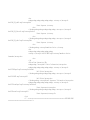
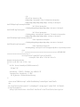
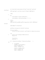
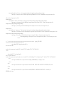
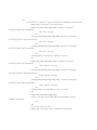
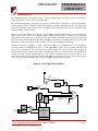
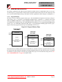
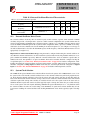
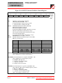
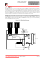
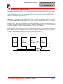
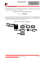
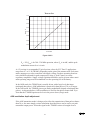
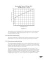
It should be noted that the peak drive current available from RXDATA increases in proportion to the filter bandwidth setting. RLPF cannot be larger than 330 kilohms (4.4 kHz
bandwidth). For low data rate operation a simple external R-C filter can be added at Pin 5
to further improve receiver sensitivity. See Figure 4.2 in the ASH Transceiver Software
Designer’s Guide for additional details.
2.5.2 Bandwidth selection
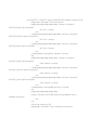
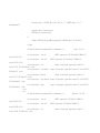
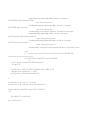
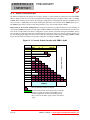
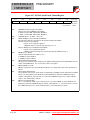
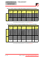
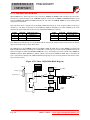
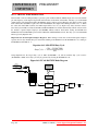
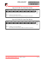
When using data slicer DS2 or data slicer DS1 with no threshold, the recommended 3 dB
bandwidth of the filter for DC-balanced data (12-bit symbol or Manchester encoding) is:
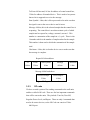
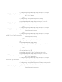
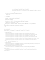
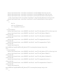
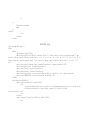
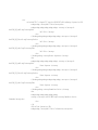
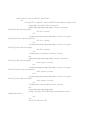
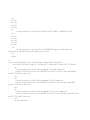
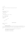
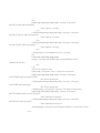
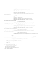
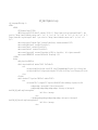
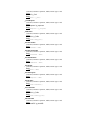
fLPF = 750/SPMIN, where fLPF is in kHz and minimum signal pulse width SPMIN is
in µs
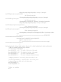
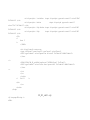
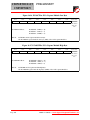
The recommended 3 dB bandwidth when using DS1 (only) with a mild threshold is:
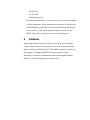
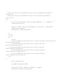
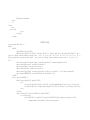
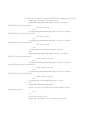
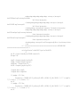
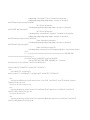
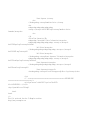
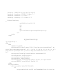
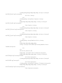
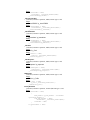
fLPF = 1000/SPMIN
The recommended 3 dB bandwidth when using DS1 (only) with a strong threshold is:
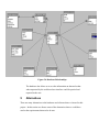
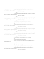
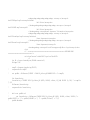
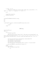
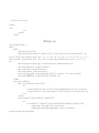
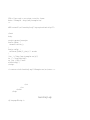
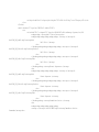
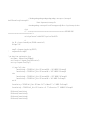
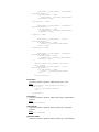
fLPF = 2500/SPMIN
2.6 Base-Band Coupling
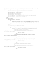
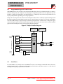
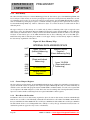
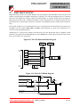
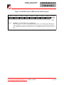
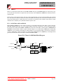
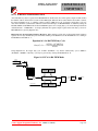
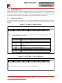
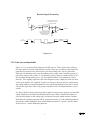
Pin 5 is the receiver base-band output pin (BBOUT). This pin drives the CMPIN (Pin 6)
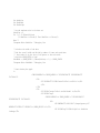
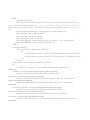
through coupling capacitor CBBO for internal data slicer operation. The time constant tBBC
for this connection is:
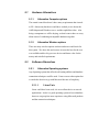
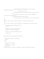
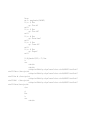
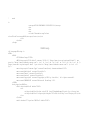
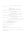
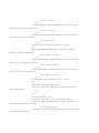
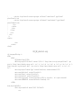
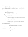
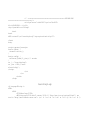
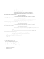
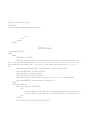
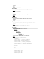
tBBC = 0.064*CBBO , where tBBC is in µs and CBBO is in pF
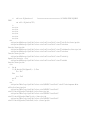
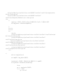
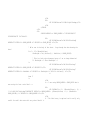
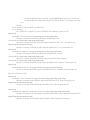
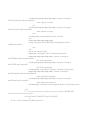
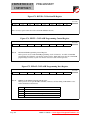
A ±10% ceramic capacitor should be used between BBOUT and CMPIN. The time constant can vary between tBBC and 1.8*tBBC with variations in supply voltage, temperature,
etc. The optimum time constant in a given circumstance will depend on the data rate, data
run length, and other factors as discussed in section 2.6.1 below.
When the transceiver is in power-down or in a transmit mode, the output impedance of
Pin 5 becomes very high. This feature helps preserve the charge on the coupling capacitor
to minimize data slicer stabilization time when the transceiver switches back to the receive mode.
2.6.1 Base-band coupling capacitor selection
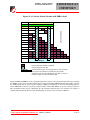
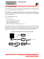
The correct value of the base-band coupling capacitor depends on the maximum pulse
width (or gap) that can occur in the signal. The maximum pulse width, in turn, depends
31
®