1
3DVIA STUDIO TUTORIAL
Designing a Game Level
OVERVIEW
In this tutorial, we’re going to develop one level of a game. The purpose of this tutorial is to point you to all
the features that 3DVIA Studio has to offer in building interactive 3D worlds; we’ll do this in the context of
building one level of a game. This level will highlight key aspects found in modern games including:
1.
2.
3.
4.
5.
6.
7.
8.
9.
Displaying and animating 3D models
Controlling the player’s character and handling input
Moving enemies within the world
Allowing the player’s character to pick up items
Handling combat between enemies and the player’s character
Implementing physics and collisions with game objects
Managing the inventory of the player’s character
Displaying the heads up display (HUD) so the player knows the state of the game
Letting the player’s character interact with in-game objects such as keys and locked doors
As we build this level, we’ll refer to a lot of useful documentation that 3DVIA has available on its website.
There is wealth of video tutorials, documentation, articles and other example projects on the 3DVIA
Studio site, and each is very focused on the knowledge it presents. This tutorial will cover what needs to
be done step-by-step in order to build a game level, and at the same time point out the important
materials online to delve deeper.
OUR APPROACH
This tutorial is designed to be used by someone new to 3D game development. Perhaps you’ve done
some programming or design work in the past, but it’s OK if you haven’t. We’ll start from the ground floor
and work our way up. Perhaps you’re a student in a university, a professional working at a studio or
someone looking to make game development a hobby. We’re happy you’re working through this tutorial,
and we’re here to help.
Building a 3D game level involves juggling a lot of topics, such as creating and managing the 3D assets
(models, textures, animations, etc.), implementing physics (e.g., collisions), handling user input to move
the player’s character in the 3D world and managing enemies and important items in the world (e.g.,
weapons and other pickups). If this is your first time building a 3D game, it might seem like there is just
too much to learn, but while it’s difficult to drink from a fire hose, it can be rewarding!
We’ll take each item step-by-step and refer to other resources to let you dig deeper to learn even more if
you’d like. If you follow each of the steps we present in this tutorial and take your time, you’ll be surprised
at what you can accomplish in just a short amount of time. 3DVIA Studio allows you to “stand on the
shoulder of giants” by leveraging a lot of work that’s already been done for you. For example, you don’t
have to implement the core physics engine that handles the collision of objects; all you need to do is
know how to use the physics component that is provided in 3DVIA Studio. We’ll point out these important
components and how to access them.
Hang in there, and if you get stuck, post to the helpful 3DVIA Community forums.
© Dassault Systèmes. All rights reserved
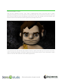
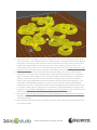
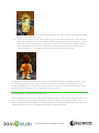
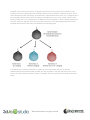
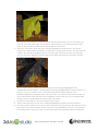
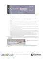
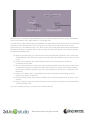
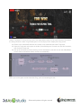
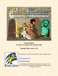
BACKGROUND STORY
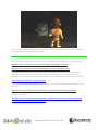
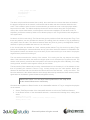
And now, let’s introduce our hero, Trog. Trog is a happy-go-lucky kind of guy who loves to collect
gemstones and hang out in his cave when he’s not hunting. But even cavemen have problems, and Trog
has a big one. While he was out enjoying a good hunt, his cave was invaded, and now infested, with
lizard men who have scattered his fortune (gemstones) throughout the cave!
Trog must find and collect bombs (his weapon of choice), destroy the lizard men and reclaim his fortune.
And so the adventure begins. We’ll build a game that lets the player control Trog on his quest to regain
control of his cave and reclaim all of his treasured gemstones.
© Dassault Systèmes. All rights reserved
RESOURCES
Before we begin, it will be important to have the proper resources for this project. First, we recommend a
good 3-button mouse with a clickable scroll wheel. This tutorial assumes you have one and is written as
such.
Second, as you go through this tutorial, you will want to visit the 3DVIA website and look at its online
documentation. It contains a wealth of information, including: video tutorials, example projects, a user
manual, articles and much more.
At the beginning of each section in this tutorial, we will refer to key documentation and video tutorials on
the 3DVIA website that you should view before proceeding. We’ll assume that you have some
background knowledge of the materials presented.
At the end of each section in this tutorial, we’ll also list links to more documentation, articles and video
tutorials on the 3DVIA website; you can follow these to dig deeper and learn more on the topics
presented if you’d like. We recommend only digging into these additional resources if you have a deep
interest, or are going through this tutorial after you’ve completed it at least once.
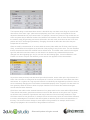
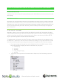
Finally, since you have this tutorial, you will likely already have many assets in the /resources sub folder.
You should also have a few sub folders within this that contain COLLADA files—(human-readable) XML
files.NOTE: these are COLLADA files because of the .dae extension. Specifically, there should be:
/lizardman
o lizardman.dae – the lizard man model (mesh) and his skeleton (rig)
o lizardman_attack.dae – the attack animation and rig
o lizardman_idle.dae – the idle animation and rig
o lizardman_jump_centered.dae – a jump animation that remains in the same location
o lizardman_jump_forward.dae – a jump animation that moves forward
o lizardman_run.dae – the run animation and rig
o lizardman_walk.dae – this walk animation and rig
/caveman
o caveman.dae – the caveman model (mesh) and his skeleton (rig)
o caveman_attack.dae – the attack animation and rig
o caveman_idle.dae – the idle animation and rig
o caveman_jump_forward.dae – a jumping animation that moves forward and rig
o caveman_run.dae – the running animation and rig
o caveman_walk.dae – the walking animation and rig
/stage
o bomb.dae – a simple bomb model (non-animated)
o diamond.dae – one of the pickups that Trog wants to collect
o ruby.dae – another pickup for Trog
o key.dae –a pickup that Trog will use to unlock doors that get in his way
o tunnels.dae –the main geometry for the cave world
o small_rock.dae and big_rock.dae – rock models that can be placed throughout the cave
o torch.dae –a model that can be placed throughout the cave to provide lighting
o door (barrier, left, right and lock) – these files construct the door model; we separate this
model into pieces to let us swing the door open in various ways (more on this later)
© Dassault Systèmes. All rights reserved
o
o
o
o
/audio
o
o
o
o
o
o
o
o
o
o
/sprites
o
o
o
o
o
o
o
o
o
door_texture.png –the UV texture map for the door model
props_texture.png –the UV texture map for all the smaller models in the scene (torch,
ruby, keyand diamond)
rock_tile.png –the tile map for the tunnel and the small and large rock models
mud_tile.png –a tile map that we’ll use to make a mud “floor” in our level
bomb_pickup.wav – the sound that plays when a bomb is picked up
door_creak.wav – the sound that plays when a door is opened
explosion.wav – the sound that plays when a bomb explodes
gems_pickup.wav – the sound that plays when a gemstone (ruby or diamond) is picked
up
heart.wav – the sound that plays when a health heart is picked up
lizard_death.wav – sound that plays when a lizard dies (when a bomb blows up near it)
lizard_lunge.wav – the sound that plays when a lizard attacks
lizard_scream.wav – the sound that plays when a lizard sees Trog
trog_background.ogg – the background music that plays as the game is running
winning.mp3 – the song that plays when the player wins the game
bomb.png – the 2D sprite for the bomb in the HUD
gem.png – the 2D sprite for the gem in the HUD
health.png – the 2D sprite for the health bar in the HUD
key.png – the 2D sprite for the key in the HUD
controls.png – the 2D sprite to show the controls and what keys to press in the game
intro.png – the 2D sprite to show the welcome/intro screen when the game starts
lose.png – the 2D sprite to show that Trog lost the game
trans_background.png – 2D sprite that is a semi-transparent background for messages
win.png – the 2D sprite to show that Trog won the game
© Dassault Systèmes. All rights reserved
CONVENTIONS
Throughout this document, we will be working with several menus. First, there are four top-level menus
(File, Edit, Views and ?). We will denote the traversing of these menus using the symbol “->” which
represents the action of continuing on to a sub-menu. This will ultimately lead to the menu item of
interest. For example:
Views->Explorers->File Explorer
The above implies that the reader is to click on the Views menu, then click on the Explorers sub menu
and finish by clicking the File Explorer menu item.
Second (as has already been used), text that is in italics is used to denote user interface elements. File
names are encased in a pair of double quotes (“”). Hyperlinks appear as blue underlined text.
Third, it is assumed that since you are reading this document, you are constructing the game level.
Tasks/actions that you are to complete are numbered sequentially (i.e. must be completed in a particular
order); we further assume that this document is to be read from top to bottom without skipping
intermediate steps. Underlined text appears in longer tasks and represents the core action of the task. It
is intended to be an aid for those who are quickly skimming the tutorial.
The term “dragging” implies left clicking the mouse, moving the mouse, then releasing the left mouse
button.
Finally, we have tried to explicitly state what should occur in each action, though once a concept is
shown, there are some actions that are left to the reader. In the event that the reader requires clearer
examples, we provide snapshots of the project during various stages.
© Dassault Systèmes. All rights reserved
STEP 1: GETTING SETUP AND CREATING THE PROJECT
PRIOR KNOW LEDGE
If you haven’t done so already, you will want to download and install 3DVIA Studio from 3DVIA’s website.
You can learn more about the download and installation process at
http://www.3dvia.com/studio/documentation/user-manual/getting-started/installing-3dvia-studio-minimumrequirements
CREATING THE PROJECT
To create a new project:
1. Start 3DVIA Studio
2. Click the Create New Project button
3. Give the project a name. In this case, we’ll call it “Trog.”
4. Click the Ok button.
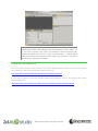
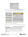
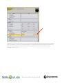
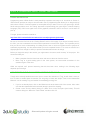
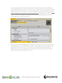
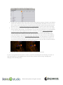
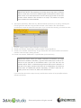
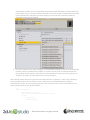
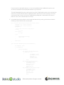
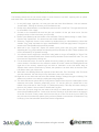
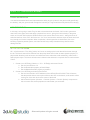
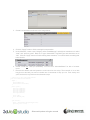
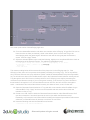
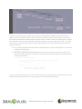
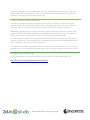
At this point, you should have a blank project that looks similar to the image below. Realize that your
project may look slightly different than this one. For example, different tabs in your windows may be
selected (shown in yellow in the image). Most importantly, make sure the Assemble tab is selected at the
bottom left of 3DVIA Studio. If it is not selected, your view will look drastically different. We will be
exploring the Behaviors and Build tabs later in this tutorial.
© Dassault Systèmes. All rights reserved
IMPORTANT NOTE: 3DVIA Studio works nicely with the local file system, so
if you want to rename your project, just browse to where the project was
created (by default this will be in you’re My Documents -> 3DVIA Studio
Public Beta folder) and rename the folder and/or the project file. The project
file will have a “mpproj” file extension.
FOR MORE INFORMATION
For more details on each of the sections of the 3DVIA Studio interface, please see the User Interface
documentation in the 3DVIA Studio User Manual located at:
http://www.3dvia.com/studio/documentation/user-manual/user-interface.
It may also be helpful to view the Interface Basics documentation, also in the 3DVIA Studio Users
Manual, located at:
http://www.3dvia.com/studio/documentation/user-manual/getting-started/interface-basics.
© Dassault Systèmes. All rights reserved
STEP 2: IMPORTING RESOURCES INTO 3DVIA STUDIO
PRIOR KNOW LEDGE
During development, one of the first things you will want to do is to import assets into 3DVIA Studio.
There are a several places from which we can import resources into 3DVIA Studio. For example, you may
have resources saved as local files on your machine. There are also several built-in resources that can
be found in the Resource Explorer (if not visible, View->Explorers->Resource Explorer). Further, many of
the fundamental building blocks for your game can be found in 3DVIA Studio’s Library tab, which include
lights, cameras and yes, plenty of action! One powerful feature of 3DVIA Studio is the ability to import
assets that have been made by the 3DVIA Community via the 3dvia.com Explorer. This contains over
20,000 assets, including: models, templates, shaders and more.
You should visit 3DVIA’s website for more information on how to use each of these as we will use several
of these while developing this game level.
IMPORTING STATIC (NON-ANIMATED) MODELS
Importing static models into 3DVIA Studio involves only a few steps. In this example, we’re going to
import the bomb model (“bomb.dae”). Though it is possible to drag the bomb directly from your file system
into the 3D View window, let’s use the File Explorer tab.
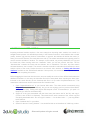
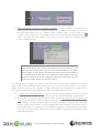
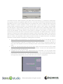
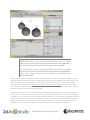
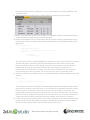
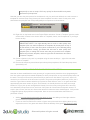
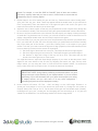
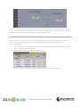
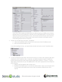
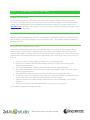
1. If the File Explorer tab is not already visible, click on Views->Explorers->File Explorer. This will
open a tab that looks like the image below. In the left pane of this tab you will see the hierarchy of
the file system of your machine. In the right pane, you will see the currently selected folder.
Browse for the file “bomb.dae”. To help locate this file, note the 3 icons
which (from left
to right) are Go to Desktop, Go Up One Directory and New Folder.
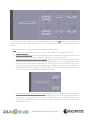
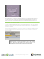
2. Click on “bomb.dae” and drag the file into the 3D View (the pane above this one). This will pull up
the Asset Import dialog window, which shows that this file is being converted into 3DVIA Studio’s
native .mp3d file format.
© Dassault Systèmes. All rights reserved
3. Click the Ok button.
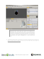
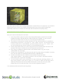
You should now see that the bomb model has been imported and is visible in both the 3D View, as well
as the Scene Graph Browser. Further (since Bomb should be selected in the Scene Graph Browser), the
Property View tab should expose many of the attributes of the bomb. The bomb may at first appear very
small…and very black! Let’s fix both.
4. With Bomb selected in the Scene Graph Browser, find Local Scale (under the Position heading)
and set its value to 300.0. This will increase the size of the bomb. You will probably also want to
zoom in a bit by placing your mouse cursor in the 3D View and scrolling with your middle mouse
button. If you still cannot see the bomb, make sure it is selected in the Scene Graph Browser,
move your mouse cursor into the 3D View and press the “e” key.
© Dassault Systèmes. All rights reserved
IMPORTANT NOTE: 3DVIA Studio uses meters as the standard unit of
measurement. A few rows under the local scale, you can see the dimensions
of the model. The dimensions in this case are very small, so we scale up by
300. The scale is a factor of the original dimensions, so you can calculate the
new dimensions of the model by multiplying the x, y, and z values by the
scale.
5. The reason the bomb is black is not because its color is black, but because there is no light in the
scene. To fix this, we will put a light in the scene: click on the Libraries tab, click on Lights and
drag a Directional Light into the 3D View.
© Dassault Systèmes. All rights reserved
6. This will pull up the Asset Import dialog again. Click Ok. The bomb should now be lit.
IMPORTANT NOTE: If you import an asset and 3DVIA Studio reports an
error, you can resolve this by right clicking on the error (which will be
highlighted in red in the import dialog box). You can then select how to
resolve the import error. For more details on this resolution process, check
out: http://www.3dvia.com/studio/documentation/user-manual/creatingcontent/asset-import.
MAKING A BOMB TEMPLATE
Because we’re going to have several bombs in our scene, all of which will be alike, now is probably a
good time to make them into a template. Once a bomb is a template, we can drag as many of them as we
like from Templates directly into the 3D View.
1. Select the Project Editor tab.
2. Right-click on Bomb and then select Create a template. You’ll notice that Templates (in the
Project Editor) now has a * by it. Expand Templates by clicking the plus symbol and you will
see that Bomb is now a template.
3. You can now delete the Bomb under the Default Stage by right-clicking on it and selecting Delete.
Alternatively, you could select Bomb and then press the Delete key.
© Dassault Systèmes. All rights reserved
IMPORTING ANIMATED MODELS
Importing animated models requires a few more steps than importing static models, but overall is a
straight-forward process. As described previously in the Resources section, each character has a model
(mesh), skeleton (rig) and any number of animations. In general, the skeleton will deform the mesh (i.e.
when you move the skeleton, the mesh with move with it). The model and skeleton are typically stored in
one file and the animation in another. For example, in this tutorial, our primary characters are Trog and
the lizard man. When looking inside the “lizardman” folder, you will see several .dae files. The file
“lizardman.dae” contains the mesh and the skeleton, but no animations. The other .dae files contain
animated skeletons, but not mesh. The reason is because it would be redundant (and inefficient) to have
multiple copies of the mesh. Realize that there are several video tutorials on working with animated
characters available on the 3DVIA Studio website. If time permits, it is recommended that you view these
tutorials before completing this section.
Before dragging the lizard man into the scene, we must modify the code to inform 3DVIA Studio about the
additional animations. In this way, the animation files will be associated when importing the lizard man.
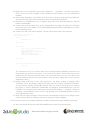
Included in the same directory as the lizardman.dae files is a file called “ImportAnimation.xml.” This
contains the code that we need to insert into the file “lizardman.dae”.
1. Open “ImportAnimation.xml” in your favorite XML editor. The video tutorial recommends using
Notepad++ (which is free to download), but you can use anything you like (such as Visual Studio,
or Expression Web). Editing with regular MS Notepad is NOT recommended; if you open it in
Notepad, you will soon understand why.
2. Select all of the code associated with the lizard man (the bottom half of the file) and copy it
(CTRL-A, then CTRL-C in Windows). This should be the entire contents of the <extra> tag and
everything associated with it. Do not copy the marker “--- for the lizard man ---“ – just copy what’s
below that line.
3. Open “lizardman.dae” in your editor.
4. Search for the text “Lizard_Skeleton.” You should find this as an id attribute of a XML tag <node>.
© Dassault Systèmes. All rights reserved
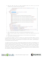
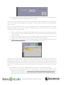
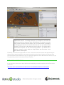
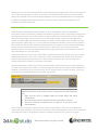
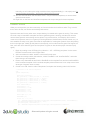
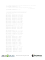
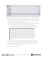
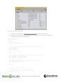
5. Paste the XML code that you copied immediately below the <node> tag. Your final
“lizardman.dae” file should look like the image below.
6. Save “lizardman.dae” then close it. You may close “ImportAnimation.xml” as well.
7. Browse in your file system to where “lizardman.dae” is located. Then drag that file into the 3D
View.
8. Note that when the Import Asset dialog appears, all the animations are imported as well.
9. Set the scale of the lizard to be 100.
To summarize the changes we made, the content in the <extra> tag tells 3DVIA Studio to load the
additional animations during import. You can see that, although the code is ugly, it is structured using
name-value pairs. For example, “ImportAnimation0” is a string with the value “attack.” “ImportAnimation1”
is a string with the value “idle” and so on.
You might note that all of the values of these strings correspond to the names of the animations in the
“lizardman” directory. During the import process, 3DVIA Studio will look for the name of the animation, or
its name prefaced with the name of the main file. For example, when importing the attack animation,
3DVIA Studio will first look for “lizardman_attack.dae” and if it doesn’t find it, will load “attack.dae.”
Knowing this, we can better organize our files by prefacing the name of the main character file before
each animation. Realize that this method reduces filename collisions since many characters will likely
have animations for walking, running and attacking.
© Dassault Systèmes. All rights reserved
HANDLING THE CAVEMAN
Beyond importing the lizard into your project, you can also import the main character, Trog, into the
3DVIA Studio IDE. This is just as easy as it was to import the lizard--you just open the DAE file for Trog
and modify it to include the XML needed to refer to the animations.
1. Open “ImportAnimation.xml” in your favorite XML editor. If it is still open from before, just make it
the active window.
2. Select all of the code associated with the caveman (the top half of the file) and copy it (CTRL-A,
then CTRL-C in Windows). This should be the entire contents of the <extra> tag and everything
associated with it. Do not copy the marker “--- for the caveman/Trog ---” – just copy what’s below
that line.
3. Open “caveman.dae” in your editor.
4. Search for the text “Caveman_Skeleton.” You should find this as an id attribute of a XML tag
<node>.
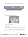
5. Paste the XML code that you copied immediately below the <node> tag. Your final
“caveman.dae” file should look like the image below.
6. Save “caveman.dae” then close it. You will want to close “ImportAnimation.xml” as well.
7. Browse in your file system to where “caveman.dae” is located. Then drag that file into the 3D
View.
8. Note that when the Import Asset dialog appears, all the animations are imported as well.
9. Set the scale of Trog to be 50. You can position him relative to the lizard man to see how they
look together.
Once you have these two characters imported, we can make use of them in our game. If you browse to
the Resource Explorer tab and open Rendering -> Animation, you should see the various animations
associated with the lizard man and Trog. Each can run, walk, attack, idle and jump. We’ll make use of
these animations for our characters in the next step.
© Dassault Systèmes. All rights reserved
RENAMING THE CHARACTERS
If you look in the Project Editor, you’ll notice that the actors that we brought into the game are named by
default according to the XML tags in the DAE file. For example, Trog is named “caveman_single_mesh”
and the lizard man is named “lizard_geo.” This isn’t always best for the actors, so we recommend
renaming the actor as soon as you drag and drop the DAE file into your project.
1. Rename the main character to be called “Trog” (right click the actor in the Project Editor and
select “Rename” or press F2).
2. Rename the lizard man to be called “Lizard” using the same technique.
FOR MORE INFORMATION
You can learn more about the process of importing assets into 3DVIA Studio in the following video
tutorial:
http://www.3dvia.com/studio/resource/tutorials/managing-art-assets-in-3dvia-studio/importing-art-assets.
Further, the online documentation has a good discussion of the asset import process at
http://www.3dvia.com/studio/documentation/user-manual/creating-content/asset-import.
For a detailed discussion of how to manage COLLADA file imports into 3DVIA Studio and the XML
formatting, please see
http://www.3dvia.com/studio/resource/articles/export-to-3dvia-studio-using-collada.
© Dassault Systèmes. All rights reserved
STEP 3: SETTING UP ANIMATION
Now that the assets of our game are imported into the project, we can begin to create behaviors for our
characters. To do this, we’ll first look at schematic scripting.
PRIOR KNOW LEDGE
There is a whole section of video tutorials dedicated to Schematic Scripting that are available on the
3DVIA website. The videos walk through creating behaviors, creating tasks, and handling user input.
Viewing these videos prior to completing this section is highly recommended.
This section is very similar in structure to the video tutorial on Applying and Blending Character
Animations, which can be found at:
http://www.3dvia.com/studio/resource/tutorials/characters/applying-and-blending-character-animations.
As such, we have tried to maintain the conventions demonstrated there. It is recommended that you view
this video before starting this section as well.
UNDERSTANDING SCRIPTING
There are two different ways you can create scripts in 3DVIA Studio. The two methods are essentially
equivalent but useful in different contexts. In this section, we’ll cover schematic scripting which will
eventually be replaced with VSL when polishing the game. If you’re interested in skipping this section,
read at least the first part. Even with VSL, it is still important to set things up correctly; the tutorial will tell
you when it’s appropriate to jump to the section on “Polishing the Game”.
Schematic scripting is a visual way to program and is very similar to flow charts in nature. If you’re a “nonprogrammer,” then this is an alternative way to get the behavior you want from your gaming while
avoiding “ugly” programming syntax (hey, did you forget a semi-colon?). Each script has a distinct entry
point (which is labeled Start), which represents the beginning of the path of execution. From there, we
stub in a series of building blocks that we can link together and configure.
You may have already noticed that there are three tabs in 3DVIA Studio located at the bottom-left of the
screen
. Up until this point, we’ve been working with the Assemble tab—essentially
because we’ve been “assembling” the world. However, we’ll now need to start organizing the actions of
Trog into Behaviors, which will be located under the Behaviors tab. Inside each behavior will be a Task
which will address a specific action. For example, we may have a separate task dedicated to changing
between the animations of Trog (e.g., change between the idle and walk animations), one to rotate him,
one to translate (i.e. move) him and so on. For now, however, we’ll only focus on changing between
animations—specifically between walk and run. There are several steps involved in this section, but they
are short (so hang in there)! We’ll start by creating a behavior for Trog.
1. Create a behavior by right clicking on the Trog node (in the Project Editor) and selecting Add New
Behavior. This will pull up a dialog box asking for this behavior’s name. Call it “characterBe,” then
click Ok. The screen will transition into the Behavior tab.
© Dassault Systèmes. All rights reserved
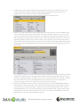
2. Before we create a new Task, we need to create a new Member for each animation that we have
for Trog. Eventually, these members will be used to create a Task. You should currently see a
blank panel. For each animation, double click on the text <New Member> and then type in the
name of the animation. To keep things simple, keep the names the same as those from the .dae
files. In other words, create a member for idle, attack, jump, jump_forward, run and walk.
3. Change the type of the member to vkAnimationResourcePtr.
4. Click the “Apply” button in the upper-right part of the panel.
5. Click on the Assemble tab at the bottom-left of the screen. In the Property View, you should now
see the behavior characterBe (next to vkSkeleton). Click on characterBe to expose each
member.
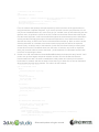
6. Finally, using the drop down menu, change the value of each member from null to the
corresponding animation. For example, change the idle member from null to the idle animation.
IMPORTANT NOTE: at this point (if you are interested), you will be able to
skip to Step 15 on “Polishing the Game” – specifically on controlling Trog with
VSL. We’ll introduce schematic scripting here and do some introductory
character controls, but we’ll need to refine these controls later in the tutorial.
We recommend that beginning users follow along here, but advanced users
of this tutorial can jump to the character controls in Step 15 and then continue
in Step 4 below.
© Dassault Systèmes. All rights reserved
Now we are ready to create a Task, which you can think of as an executable item. The previous steps
expose the animations—making them visible when building tasks. In other words, by linking these
members to the animations, we can now access them when constructing the animation task. As stated
before, the task will be comprised of a series of visual building blocks that we will configure and then link
together.
7. To create a task, start by clicking on the Behaviors tab. Make sure that the characterBe behavior
is selected (which it should be since we have only one behavior) in the top left.
8. Double-click on <New Task> to create a new Task. You should see a dialog box prompting you
for a name. Call this task “AnimationManager”. Then, click OK.
You should now see the visual representation of a script called the schematic window. The script is
currently empty. However, you should note that there is an entry point (labeled Start) that represents the
beginning of our script. It’s now our job to construct a series of nodes, called a graph, which represents
the program. You should realize that, even though this Behaviors View of your program is 2D, interacting
in this environment is very similar to interacting in the 3D environment. In other words, it is possible to
zoom in and out with the scroll wheel and dragging while holding ALT-middle-mouse will pan the screen.
You should also realize that there are two ways to drop the building blocks into the schematic window.
The first way is to drag and drop them from the Building Blocks tab by selecting one of the presets and
the dragging one of its functions (located in the pane below) into the window. The second way is to hold
the CTRL key and then double click on the schematic window. This will pull up a text field and allow you
to type in the name of the function you are looking for— we’ll use the later in this example.
© Dassault Systèmes. All rights reserved
9. To begin, we need to find the idle animation. To do this, press and hold the CTRL button and
double click in the schematic. This should present a text field. In it, type in “findanimation” and
press the return/enter key. This will create the first node in the animation graph. Note there are
several “pins” on this node that we will need to configure.
10. Create a second building block in a similar fashion called “enqueueanimation.”
11. Connect Start to the In pin of the Find Animation (the left-most pin) by clicking inside Start,
dragging between these two pins and releasing the mouse in the In pin of Find Animation. Then
connect the Out pin of Find Animation to the In pin of Enqueue Animation. Note that we now have
two “steps” in our script. Also note If you mouse over the pins while holding CTRL, you will be
able to see the labels. Your graph should look like the image below.
12. Now we need to be able to access the animation from the script. To do this, click off of Enqueue
Animation (i.e. make sure it’s not selected) and then select the Target tab. Expand characterBe
© Dassault Systèmes. All rights reserved
and then select the Exp checkbox for each animation. This “exposes” the animations for us to use
in our programming. Leave the Target tab open.
13. Next, we need to be able to access the skeleton of Trog. To do this, we’ll need to create a new
member within the Target tab; be sure to do this in the Target tab and NOT the Members of the
characterBe tab. Double click on <New Member> and type in “skeleton.” Change the type of this
member to be vkSkeletonPtr. Press the Apply button and then click the Target tab to minimize it.
We now have a reference to Trog’s skeleton!
14. The top-left pin for both building blocks is of type vkSkeletonPtr, so click inside of each pin and
drag out of it. When you release, a context-specific dialog will expose the “skeleton” member
created in the previous step. Click on the skeleton menu item.
15. The second pin for Find Animation expects a vkAnimationResourcePtr, which we made in a
previous step. Similar to the previous step, drag from the inside of this pin to outside and then
select the “characterBe.idle” animation from the menu. This building block now returns the idle
animation through the bottom pin.
16. Connect the Out (bottom) pin of Find Animation to the second pin of Enqueue Animation (the one
that expects a vkSkeletonAnimationPtr. Your graph should look like the image below:
© Dassault Systèmes. All rights reserved
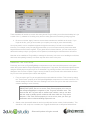
17. Set the remainder of the pins in Enqueue Animation by double clicking in the middle of the
building block which will make a dialog box appear. Set the values in this dialog box to those in
the image below (Start Time = 0, Transition Mode = eBreak, Layer = 0, Loop Count = 0 and
Forward = true). At this point, it is possible to return to the Assemble tab and press the Play
button in the upper left of the window. If you do this, be sure to rewind the animation and then
return to the Behavior tab.
IMPORTANT NOTE: If you forget to stop playing the game’s preview (i.e. you
don’t click the “rewind” button), then you are in a pseudo read only view within
3DVIA Studio. In such a state, you cannot do certain tasks, such as adding a
new member as we’ll do below. If you find that the “add member” option isn’t
present, it’s because you’re still running your game in preview mode. Be sure
to click the “rewind” button and all will be correct.
We currently have two steps in our script. For the next steps, we’ll set up the keyboard to be able to
control Trog’s forward walking animation using the ‘W’ key; this will eventually lead us to the popular
WASD movement control for our character. To begin, we need to get the keyboard and make it into a
local variable for this script (meaning that the variable is only visible within this script).
18. To create a keyboard building block, CTRL click on the schematic background to get a text field
and then type “vkIO” and you should be able to select the vkiodevicemanager::keyboard item.
19. Because we’ll be using the keyboard several times, we will make it into a local variable for this
script. To do that, click off of any building block and then click on the Local tab. Double click on
<New Member>, name the variable “keyboard” and change its type to vkKeyboardPtr. Click Apply
and then minimize the Local tab. Finish by dragging from within the bottom pin (the Return pin) of
the keyboard block to a blank part of the schematic (pulling up a menu) and select keyboard.
From now on, we’ll be able to use this local variable instead of creating several instances of the
keyboard building block.
© Dassault Systèmes. All rights reserved
20. Connect the true pin (top right) from Enqueue Animation to the In pin of the Keyboard block.
Acquiring the keyboard is now the third step in our script.
At this point, you may begin to run out of room in the schematic window. Realize that you can expand the
grid to an arbitrary size by dragging one its edges or simply attempt to drag one of the components
outside the grid.
Next we need to determine if the ‘W’ key is pressed, and if so, change the animation to the walk
animation. Further, if the ‘W’ key is released, we need to return to the idle animation. To do that, we’ll
work with the isKeyPressed function.
21. CTRL double click on the schematic grid to obtain a text field and type in “iskeypressed” and then
return. Connect the Out pin of the keyboard block to the In pin of the isKeyPressed block (making
it the fourth step).
22. Connect the Target pin (first top) of the isKeyPressed block to the keyboard variable by mouse
dragging from inside the pin to outside the pin. Select keyboard from the menu.
23. Program the key to respond to ‘W’ by double clicking on the isKeyPressed block. Press the
Capture button and then press the ‘W’ key. The value will become “eW.”
Note that you can CTRL click on a pin to show more information. You might want to do this for the top,
right pin to show which key this building block responds to. Also, realize that the top pin (on the side) of
this building block is the true pin, meaning, in this case, that if the ‘W’ key is pressed, this path is taken;
we would want to trigger the next animation if this were the case. The bottom, side pin is the false pin, at
which point we will loop back to the In pin of the isKeyPressed building block and wait for the next key
press.
24. Connect the false pin of the isKeyPressed block to the In pin of the isKeyPressed block.
25. We now have to handle the case if ‘W’ is being pressed. In that case, we have to find the walk
animation and then enqueue it. Copy the Find Animation and Enqueue Animation blocks by
selecting both (by dragging around both), then press CTRL SHIFT C to copy and preserve all
links. Then, paste using CTRL V. Move the new blocks to the right of the isKeyPressed block and
© Dassault Systèmes. All rights reserved
delete the In pin connection for the new Find Animation block. Then, connect the Out pin of
isKeyPressed to the In pin of the Find Animation block. Your graph should look like the (partial)
image shown below.
IMPORTANT NOTE: If you go back to the ‘Assemble’ view and run/preview
your game in the 3D View, be sure to click in the 3D View so it has focus; if
you forget to do this, your keyboard input won’t be processed, so it’ll appear
as if the script isn’t working (even though it is indeed correct)!
26. Next, re-connect the vkSkeletonPtr pins for these two new nodes back to the “skeleton” member
(dragging from inside to outside the pin).
27. Connect the vkAnimationResourcePtr of the new Find Animation block to characterBe.walk.
28. Double click on the new Enqueue Animation block to pull up the dialog. Change the transition to
eTransition for a smooth transition between idle and walk.
29. Next, select the isKeyPressed block and the press CTRL SHIFT C to copy it. Then paste it to the
right of the last Enqueue Animation block.
30. Connect the true pin (top-side pin) from Enqueue Animation to the In pin of the new isKeyPressed
block and re-connect its vkKeyboardPtr pin to the local keyboard variable (drag from inside of the
pin to outside the pin).
31. We need to change the true output of the new isKeyPressed block. In this case, we want the true
output to loop back to the In pin of the block, meaning as long as the ‘W’ is being pressed, stay in
the walk animation.
32. We also need to change animation states back to idle for the false pin of the last isKeyPressed
block. To do this, copy the first two blocks (the Find Animation and Enqueue Animation blocks)
using CTRL SHIFT C and paste them to the right of the last block using CTRL V.
33. Change the pin settings for the Find Animation block. Start by deleting the current connection of
the In pin of the Find Animation block and change it to the false output pin of the isKeyPressed
© Dassault Systèmes. All rights reserved
block. Next, change the vkAnimationResourcePtr to characterBe.idle. Also, don’t forget to reconnect the vkSkeletonPtr pins for the new Find Animation and Enqueue Animation blocks.
34. Finally, double click on the last Enqueue Animation block and change its transition to eTransition.
Finish the script by connecting the true pin of the last Enqueue Animation block back to the input
of the first isKeyPressed block.
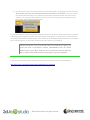
If you followed the directions above, your script should look like this:
You should now be able to go back to the Assemble tab and press the Play button; you may need to click
on header of the 3D View panel before doing this. As you can see, we now have the ability to smoothly
transition between the idle and walk animations. We will need to do very similar steps when setting up the
other animations as you will see later in this tutorial.
FOR MORE INFORMATION
Remember, there is an excellent video tutorial on Applying and Blending Character Animations, which
can be found at:
http://www.3dvia.com/studio/resource/tutorials/characters/applying-and-blending-character-animations.
© Dassault Systèmes. All rights reserved
STEP 4: BUILDING THE SCENE’S GEOMETRY
PRIOR KNOW LEDGE
You should know how to import assets into the 3DVIA Studio program using the drag and drop method.
IMPLEMENTATION
Now that you have an idea of how to import assets (like you did with Trog and the lizard man), let’s now
build the scene. In this step, we’ll establish the main geometry for the scene. We should define the cave
walls of Trog’ home.
1. Import the “Tunnels.dae” file into the scene of your 3DVIA Studio level: this is located in the
“Stage” folder within the “Assets” folder of the assets we provided to you. If you need details on
how to perform this import process, please refer back to Step 2 (where we showed how to import
the bomb model). Center and zoom in on this newly imported model.
2. Set its local scale to 300.
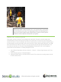
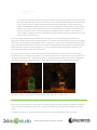
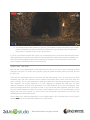
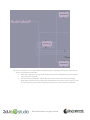
If you did this correctly, you should see a nice cave layout with walls in a mazelike fashion. This is Trog’s
home. We need to do some more work to establish all of the other aspects of the space, but this general
geography sets the primary geometric characteristics of the level we’ll build. You should see something
like this:
© Dassault Systèmes. All rights reserved
IMPORTANT NOTE: You might notice that your scene is a little dark. This is
because you only have one directional light placed in the scene, so shadows
dominate the space. You can improve this by placing additional directional
lights each angled/oriented in a different way so the entire scene is well lit
globally, or you can import a “Three Point Lighting” actor from the 3dvia.com
Explorer by clicking this tab open, logging in, searching for the “Three Point
Lighting” and dragging it into the scene.
You might also notice that the Trog and the lizard men actors that are in the scene are of appropriate size
relative to this large cave system, but they might be colliding and halfway stuck through the floor of the
cave tunnels model. We’ll adjust them later and make them look nicer.
To establish a “floor” within our scene, we’d like to use a mud texture that is present on the floor of our
cave. We can achieve this by using a flat plane actor and setting the properties of this plane to have a
mud texture/image repeated. We can then position this plane such that it appears at the bottom of our
cave geometry and just slightly intersects above the bottom of the cave/walls geometry.
1. To begin, select a Plane 10x10 from the Libraries View (the Plane 10x10 is located in Models ->
Primitives within the “Samples” subsection of the Libraries view). Add this Plane 10x10 to the
scene.
2. Rename the actor to be “PlaneMudFloor” in the Project Editor.
3. You’ll notice that the plane is too small, so change its Local Scale to 50--this size should establish
a white plane that extends just beyond the level’s cave geometry. Notice that our cave world
geometry is about 1.0x1.5, which is why the local scaling of 50 on a 10x10 plane provides a plane
large enough to extend just beyond the cave wall boundaries.
4. We need to establish a texture for the plane so that we can avoid the “blank white” default
material of the plane. Set the Material Override property of the PlaneMudFloor to be Plane_0_div,
the new blank material that was created when you added the plane to the scene. Next, we’ll
configure the material that is now associated with the plane.
5. Before we can set the texture, we need to import it. Locate the “Mud_Tile.png” texture within the
“Scene” folder of the “Assets” folder for the assets we provided to you. Drag and drop this PNG
graphics file into the main 3D View of the Studio IDE and click “OK” when prompted. Now this
asset is available to us.
Next, we need to ensure that the texture is “tiled,” i.e. that it repeats over and over again along the X and
Y axis of the plane. We do this so that we don’t have to generate a very large texture that would consume
too much memory. In general, a well-designed texture can be repeated along the plane without negative
visual impact. To establish this tiling effect, click on the property editor icon for the Material Override
property of the Plane actor. This icon is located as shown in the following figure:
© Dassault Systèmes. All rights reserved
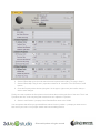
When you click this property editor icon, you will be presented with a floating window that lets you modify
specific properties. In this case, we need to modify the material’s diffuse map and diffuse map tiling, but
you’ll see in the following figure that there are many properties of the material that we could edit
(specular, ambient, etc.).
© Dassault Systèmes. All rights reserved
6. Set the Diffuse Map to be the mud texture that we imported earlier (Mud_Tile.png) in Step 5.
7. Set the Diffuse Map Tiling X and Y properties to both be 30. Leave the Z at 0 since this is a 2D
texture.
8. Close the Property editor window (using the X in the upper, right corner) and confirm that you
want to save changes.
Finally, we need to position the floor plane so that it shows the mud along the floor of the cave. The X and
Z positions are fine, so the only thing that must be done is to adjust the Y position:
9. Set the Local Position Y property of the PlaneMudFloor actor to be 0.0003.
You can explore what effect you get with different values for the Y position— perhaps you want more or
less mud in your scene. Your project should now look something like this:
© Dassault Systèmes. All rights reserved
IMPORTANT NOTE: To manage resources, it is helpful to work with the
different views of your resources within 3DVIA Studio. For example, it is quite
easy to add a resource (model, texture, etc.) into 3DVIA Studio by dragging
and dropping the resource into the 3D View, but how can you delete it once
it’s there? You can see all the resources you are using in your project within
the Resource Explorer, as well as the Project Editor. If you would like to
remove a resource, view it within the Project Editor and then select it and
press Delete or Backspace.
Eventually, we’ll add some props within our level. These will include the torches that appear along the
walls at various spots through the cave system and also the pickup items like gems, bombs and keys.
We’ll later add the doors that hinder Trog from going throughout the world. But before we do this, let’s get
Trog wandering around in the tunnels that we’ve added.
FOR MORE INFORMATION
If you would like to learn more about shaders and establishing material properties within 3DVIA Studio,
please see
http://www.3dvia.com/studio/documentation/user-manual/shaders/shaders-in-3dvia-studio.
© Dassault Systèmes. All rights reserved
STEP 5: HANDLING INPUT FROM THE USER
PRIOR KNOW LEDGE
Programming within 3DVIA Studio is both powerfully expressive and easy to do. As shown in Section 3,
3DVIA Studio provides an easy-to-use schematic view of programming that allows you to drag and drop
and connect “blocks” of actions together to accomplish what you want to occur in your game logic. 3DVIA
Studio also provides a more “line coding” approach to implementing your game logic in Virtools Scripting
Language (VSL). We’ll once again focus on the graphical, schematic view for now as it is a bit easier to
pick up.
To begin, please review the material at:
http://www.3dvia.com/studio/documentation/user-manual/programming/schematic.
Be sure to view the five links in the “Getting Started” section of this page if you haven’t already done so.
It’s OK if you don’t understand all of the material presented on these Web pages. The important point is
that you have a basic understanding of building blocks, how to link them together and the purpose of
schematic programming. It is also assumed that you have completed Section 3. As such, we will work at a
slightly higher level, though we will try to provide reminders about how to do things.
Before you begin this step in the tutorial, you might want to do some small “cleanup” of the project. We
recommend that you:
Make a template from the lizard man actor and remove the actor from the scene.
Move Trog to a good starting point in the cave system; we recommend somewhere in the
southern region of the cave.
While not required, we’ll proceed assuming that this has been done; nothing in the following steps
depends upon it though.
IMPLEMENTING THE CHARACTER CONTROLS TO MOVE
Though we’ve already handled some user input to control the animation of Trog, he still doesn’t move or
turn! In order to enable these movements, we are going to create two simple Tasks in the characterBe
Behavior: one for rotating Trog and another for translating (moving) him.
1. If you’re not already there, click on the Behaviors tab at the bottom left of the screen. Also, make
sure that the characterBe tab is selected (though it should be already).
2. Create a new Task by double clicking on <New Task> in the Task pane (see below). This will
create a dialog box. Name the Task “Rotate” and then click OK.
© Dassault Systèmes. All rights reserved
You should now see a blank schematic grid (which should look familiar). To construct the rotate script,
we’re going to acquire the keyboard (again) and use it as the input to two different IsKeyPressed blocks,
specifically for keys ‘A’ and ‘D.’When those keys are pressed, we’ll want to rotate the main mesh node
either clockwise or counter clockwise. Further, we want this to occur at a particular rate, meaning a
certain number of radians per second. If you’ve forgotten what a “radian” is, don’t sweat it. Just remember
that 360 degrees is approximately 6.28 radians, so the input values will be considerably smaller. Also,
realize that we’ll be rotating our characters just a little bit per frame, but that amount will depend on how
much time has passed. In other words, for every frame of animation in our game (i.e. every time the
screen draws), the script will check to see how much time has passed, and based on that time, rotate the
character a certain amount: larger elapsed time between frames means larger rotations. The reason we
want to base the rotation on time is because not all computers will render (draw) the screen at the same
speed. If rotations and translations were based on frame rate alone, the game could be a very different
experience on each machine it is played on. Knowing that, let’s continue.
3. Add an instance of the keyboard to our script and connect it from start. To do this, remember to
CTRL double click on a blank part of the schematic grid. This will create a text field. Type in
“vkiodevicemanager::keyboard” (or actually just type “vkio” and click it). Connect the Start pin to
the In pin of the keyboard. It won’t be necessary to create a local variable called keyboard for this
script.
4. Create two IsKeyPressed blocks and connect them. Again, this can be done by CTRL double
clicking and typing in “iskeypressed” and pressing enter/return. Link the Out of the keyboard block
to the In pins of each of these blocks.
5. Configure the top two pins for each isKeyPressed block. Remember, you can program these
blocks by double clicking on them and then capturing the key. Also, connect the bottom pin of the
keyboard block to the top left pin of each IsKeyPressed block. Your current graph should look like
the image below. Remember, you can CTRL click a pin to show its configuration.
© Dassault Systèmes. All rights reserved
6. Connect the false pin of each IsKeyPressed block to its In pin. The reason we do this is because
if the key is being pressed, we want to loop back and check for it again. If you’re wondering what
the little clock icon
does, it means wait one frame before polling for another key press.
7. Create two PerSecond blocks and configure them. CTRL double click again and type
“persecond.” Program each by double clicking on them and giving a value of 2.0. Connect the
true pin from each corresponding IsKeyPressed block to the In pin of each PerSecond block.
Your current graph should look like the image below:
8. Create two Rotate blocks and connect them. Once again, CTRL double click and type in “rotate.”
Connect the Out pins of each PerSecond block to the In pins of each corresponding Rotate block.
9. Create a “node” member in the Target tab. We need to be able to access Trog entirely, so we
need a member that links to him. To create one, click outside of any block (i.e. on the background
of the schematic), click the Target tab and then double click <New Member>. Name the member
“node” and make sure its type is vkNode3DPtr (which it should be by default). Click Apply and
then hide the Target tab by clicking on it.
10. Configure each Rotate block. Start with the Target pin (upper left) by dragging from inside the pin
to outside and then selecting node: this was the member we just created. Double click the first
Rotate block (the one bound to the ‘A’ key) and change its values to x = 0.0, y = -1.0 and z = 0.0.
We’ll configure the rest of these later. Do the same process for the Rotate block bound to the ‘D’
key, except change its values to x = 0.0, y = 1.0 and z = 0.0. These values mean that the rotation
will occur around the y (up) axis.
11. Connect the remaining pins for the Rotate blocks. Connect the Output (bottom) pin of each
PerSecond block to the RadAngle (top-middle) pin of the corresponding Rotate block. Connect
th
the Space pin (top 4 ) to the node member (drag inside the pin to outside the pin) and connect
the Out pin of each Rotate block back to the corresponding In pin of the IsKeyPressed block.
Note that these lines have (and need) a frame break
on them. Your final graph should look like
the image below:
© Dassault Systèmes. All rights reserved
You should now be able to go back to the Assemble tab, press the Play
button and turn Trog left and
right using the ‘A’ and ‘D’ keys. Make sure you click on the header of the 3D View to give focus to the
window.
In a very similar fashion, we’ll create a task for translating (moving) Trog.
1. Create a new Task by double clicking on <New Task>. Name it “Translate” and click OK.
2. Create a Keyboard block by CTRL double clicking on the schematic grid and typing “vkio” (to find
vkiodevicemanager::keyboard). Connect the Start pin to the In pin of this block.
3. Create and configure two IsKeyPressed blocks. Configure them in the same way as the Rotate
script above by connecting the Out pin of the Keyboard to the In pin of each IsKeyPressed block.
Configure one of these blocks to respond to the ‘W’ key and the other to respond to the ‘S’ key.
The ReturnValue (bottom) pin of the Keyboard block should be connected to the Target pin of
each IsKeyPressed block. Finally, connect the false pin from each IsKeyPressed block back into
its In pin. Your current graph should look like the one below:
4. Create and configure two PerSecond blocks in a similar fashion, connecting the true pin from the
IsKeyPressed block to the In pin of the PerSecond blocks. For the value of the PerSecond block
bound to the ‘W’ key, change it to -0.1. For the corresponding ‘S’ block, change its value to 0.1.
This may seem backwards, but it is because “forward” is along the –z axis. We’ll connect the
remaining pins soon.
© Dassault Systèmes. All rights reserved
IMPORTANT NOTE: The movement rate of your character should be set to a
value that is appropriate to the size of the world. In this case, we use 0.1 to
translate forward and backward since our world is sized to be about 1 meter
in width. Be sure to consider the size of your world when defining your
movement rate within the world, otherwise, your character will move too fast
or too slow.
5. Create a “node” member. This is done the same way as in the Rotate task we previously created.
Click on the Target tag, double click on <New Member> and call it “node.” The type should
default to vkNode3D. Click Apply and hide the Target tab by clicking on it.
6. Create two Translate blocks by CTRL double clicking and typing “translate.” Before we connect
this block to others, however, we need to decompose the translation pin into its separate x, y and
z components. To do this, right click on the translation pin (the second top pin) and select Export
Members->x (see image below). Do the same thing for the y and z components. You can now
right click on the translation pin and then click on Remove Export.
By doing this export pin process, we can display the individual components of a pin (in this case,
the X, Y and Z components). This is useful to connect other pins coming out of other blocks into
very specific pins (in this case, we’re about to connect to the Z pin).
7. Connect the Translate blocks. First, connect the Out pins of the PerSecond blocks to the In pins
of the corresponding Translate blocks. Then connect the Output pins (bottom pin) of the
PerSecond blocks to the z inputs you created in the previous step. Next, connect the Target pins
to the “node” member by clicking inside and dragging to outside of them. Finally, connect the Out
pin of each Translate block to the In pin of the corresponding IsKeyPressed block.
8. As the last step, set the Space input (second to last) to be a reference to the “node” member by
clicking inside and dragging to outside of them. Your final graph should look like the one below:
© Dassault Systèmes. All rights reserved
At this point, you can switch to the Assemble tab and run your game by clicking on the Run icon (don’t
forget to click within the 3D View to make it active). You’ll see that you can move Trog around the world,
and he will walk forward, backward and rotate left and right based upon the user pressing WASD keys. If
you play the game, you should see Trog walking around in the world.
The trouble you’ll notice is that the camera is fixed in space, so it doesn’t create a very good, believable
game to see outside the scope of the cave system. For example, when a player is playing the game, they
should only see what Trog might see—using an over-the-shoulder third-person perspective camera or by
© Dassault Systèmes. All rights reserved
using a first-person camera. The decision as to which camera type to use is up to the style of game
you’re creating. For this Trog game, we’ll make use of a third-person camera.
ADDING A THRID-PERSON CAMERA
There is a nice built-in, Third-Person Camera available for download in the 3DVIA Explorer. Log in now
and search for or browse to the Third-Person Camera. What we want to do is add this camera and bind it
to our Trog actor so that when the actor moves in the world, the camera follows. The camera will be an
“over the shoulders” view of Trog walking around in the scene.
Before you add the camera to our scene, there is something else that we need to do. From our
experience (and this is a common problem among cameras in 3D environments), you’ll experience
“jittering” of the camera if you add it into the scene incorrectly. Specifically, if you just add the third-person
camera as a sub-actor of Trog, then you’ll get a jittering effect as the camera jumps around ever so
slightly; this is a small effect, but it’s quite annoying. There is a specific technique that will overcome this
jittering problem, and that’s to create a Node that holds the Trog actor and the third-person camera as
“siblings” within the scene. Let’s implement that now:
1. Begin by browsing to Libraries -> 3D -> 3D Entity and adding this 3D Entity into the Project Editor
(drop it onto the DefaultStage).
2. Rename it from New 3DEntity and call it MainCharacter.
3. Drag and drop the Trog actor onto the MainCharacter so that Trog is a sub-actor of the
MainCharacter.
4. Now, search for the Third-Person Camera in the 3DVIA Explorer and drag and drop it onto the
MainCharacter node in the Project Editor; be sure to confirm (i.e. click OK) when the import dialog
appears. If you did these steps correctly, you should see the following in the Project Editor when
you expand the MainCharacter node (i.e. click the plus icon to the left of the MainCharacter
name):
© Dassault Systèmes. All rights reserved
This associates the two actors, Trog and the ThirdPersonCamera, together logically within our
project, but it doesn’t bind the Third-Person Camera to the Trog character. If you run the game
and switch to the Third-Person Camera in the 3D View, you’ll still see that the Third-Person
Camera is stationary and isn’t bound to the Trog character. Let’s fix that next.
5. Adjust the properties of the third-person camera. First, click on the ThirdPersonCameraBe
behavior in the component ring and then set the properties to match the following:
The most important property is the “Third Person” property. Be sure to pick the Trog skeleton
entity to make sure that the camera will be bound to this entity and move along with it. You’ll also
want to position the camera behind and slightly above the character, and this is set with the
“Camera Position In Ref.” You can specify where the camera is looking using the “Eye Target
Position In Ref” property. Finally, the last important property is the “Camera Stiffness.” If you want
the camera to follow directly oriented along with the actor, set this to 100; if you want it to be
‘loser’ then set this lower down to near 0.
6. Once you have ensured that the properties in your game match those shown in the graphic
above, switch to the vkCamera component (shown below)
and set the “Near Clip” property to be 1.0 and the “Far Clip” property to be 200. This means that
only elements within this view frustum of the camera will be rendered to the screen. You can
adjust these properties to see how the near and far clipping planes change what is and isn’t
rendered when you run your game. It’s important to select this well to ensure that your game
displays what’s needed but is also optimized for performance (i.e. you don’t have your far plane
set too far out so that too much is rendered).
7. At this point, you can optionally position the ThirdPersonCamera so that it’s position just behind
Trog and also oriented to where it’s looking at him. This is optional since the camera will
automatically “snap” into the correct position when the game runs, but it’s also a nice idea to
place it near where you want it to begin so that when you run the game it doesn’t fly through walls
in order to get to the correct spot!
© Dassault Systèmes. All rights reserved
8. Run the game and you should see that the camera follows the Trog character around the world.
Be sure that you have the Third-PersonCamera selected in the 3D View in order to actually
see this behavior because you’re probably still using the authoring camera view (since this is
default). You can select which camera is active in the 3D View by using the drop down in the
upper left of the 3D View as shown below:
It’s important that you know how to switch between cameras in the 3DVIA Studio environment. Using the
Authoring Camera is good to position and orient objects in the world, so switch back to it whenever you
are modifying the world and updating the scene. Switch to the ThirdPersonCamera whenever you want to
play or test your game, or see how it will look to the user when they are playing.
IMPORTANT NOTE: If you’d like to add a little more polish to your game, you
could also add a First-Person Camera (downloadable from the 3DVIA
Explorer site) to your game. Bind it to the Trog character and then allow the
user to switch which camera is active by pressing a key on the keyboard.
FOR MORE INFORMATION
There is a nice tutorial on how to handle user input from a keyboard, mouse, and gamepad at
http://www.3dvia.com/studio/resource/articles/handling-input-devices.
© Dassault Systèmes. All rights reserved
STEP 6: ENABLING PHYSICS
PRIOR KNOW LEDGE
Now that we have our character and level geometry in place and the player can move the character
around the world, we need a means to ensure the character doesn’t walk through walls and that basic
physics is established in our world.
Before we begin implementing physics in our game, please view the following
http://www.3dvia.com/studio/resource/tutorials/characters/character-collisions
and
http://www.3dvia.com/studio/resource/tutorials/characters/character-controls.
After viewing these video tutorials, you will have an understanding of how we can implement physics
interactions within our Trog game.
IMPLEMENTATION
At this point in our game development process, we have our Trog character in our scene and have
created the level’s geometry. We’ve also added the ability to move Trog around using some Schematic
scripting to allow the player to move Trog via the WASD keyboard input.
If you have followed the directions in this tutorial thus far and run the game, you’ll notice that if you move
Trog over to a wall, he’ll pass right through. This is because we haven’t set up the constraints to tell the
game how Trog should interact with the objects around him. While we know what should occur (i.e. Trog
should bounce off the walls or not be able to walk through them), our scene needs to be properly set up
to act upon our wishes.
If you were to build your own game from scratch, implementing all of the physics and interaction
behaviors between all the objects in the game could take months of your time. Fortunately, 3DVIA Studio
provides some very nice built-in components that we can utilize that will handle all of these interactions
for us, and we can add these features to our game in a matter of minutes!
Let’s now add some constraints to the Trog character in our scene so that he properly interacts with other
in-game objects and the terrain.
1. To begin, select the Trog main character mesh node from the Project Editor. Notice that he has a
bounding volume that indicates where the mesh’s extents (boundaries are) as shown below.
© Dassault Systèmes. All rights reserved
It is our intention in this phase of the tutorial to apply a component to Trog so that his bounding
capsule acts as a constraint that will not allow him to pass through objects in the game’s world.
IMPORTANT NOTE: It’s important to ensure that you have “set up” the Trog
main character hierarchy properly now that we’re getting into the physics
engine aspects of our game. Be sure that you have set the Trog vkEntity3D
Local Position values to 0/0/0 in X/Y/Z and have moved the Main Character
actor into the correct position in the world rather than moved the Trog subactor in the world. This is important because otherwise there will be confusion
as to where in the world space Trog actually resides. We want the
MainCharacter to be displaced/moved, and then the sub-actors for the
camera and Trog will automatically be moved too. We also need to scale Trog
to 100 (to make him a little bigger than his current value of 50). Set the Local
Scale property of Trog to be 100.
2. In order to implement physics in our game world, we need to know what objects should be
handled by the physics engine. Additionally, we need know in what space (i.e. where within our
world) the physics might occur. In order to optimize this and make the computations to perform
the physics doable in real time (i.e. fast), we need to set up some properties within our game
world. To begin, we need to limit the space in which we want physics to be computed. We can do
this in 3DVIA Studio by defining a Physics World actor and setting its bounding dimensions.
Then, anything within this Physics World will work properly. Add a Physics World to our scene by
selecting Libraries -> Physics -> Physical World and dragging this into our scene. Next, set the
gravity property to be -20 in the Y and the Size property to be 400/30/500 in the X/Y/Z. You can
change the gravity value to get different effects/feel for your game, but for this game, -20 will work
best for what we’re trying to achieve.
3. The next thing you should do is click on a rock wall within the game’s scene. We need to add a
vkPhysicsRigidObject component to the Tunnels_Model (main rock walls) actor. This
vkPhysicisRigidObject component ensures that it interacts with other actors in the world through
the rules of physics. This includes enforcing that the actor is solid and other actors shouldn’t pass
through it. Realize that there is a difference between an actor showing up in the scene and an
© Dassault Systèmes. All rights reserved
actor being physically realized (and interacting with other objects) in the scene. By adding the
“vkPhyisicsRigidObject” component to an actor, we are saying that this actor should be a physical
solid and react in the world as such. It saves a lot of time and is nice that the 3DVIA Studio game
engine will handle all of the details for us if we just utilize the already defined components. Add a
vkPhysicsRigidObject component to the Tunnels_Model actor by selecting it from Libraries ->
Physics -> Physics Rigid Object in the Libraries tab. Drag and drop this component onto the
Tunnels_Model actor in the Project Editor.
4. When you add the vkPhyiscsRigidObject component to an actor, you can select the Shape Type
in the Property View. In the case of the cave walls (Tunnels_Model), we want to ensure that the
physics shape of the model is seen as each face of the mesh. Select vkPhysicsMesh as the
Shape Type and you’ll get a world where the walls and floor act as you would expect and the
following visual result when designing your level:
© Dassault Systèmes. All rights reserved
5. If you save and run your game, you’ll notice that the tunnel mesh “falls” when you run the game.
This is because it’s now a physical object in a physical world, so gravity (and all the other physics
rules) apply. Of course, we don’t want our tunnel to “fall” when we run the game, so we can fix it
in space by setting the Motion Type property of the Tunnels_Model to be set to Fixed. This
means that we don’t want it to move, but other things can collide with it. Change the Motion Type
property to be Fixed now and rerun the game to see that the cave is now stationary.
6. Next, reselect the main Trog mesh node from the Project Editor. We need to add a Physics
component to this mesh node to indicate that the Trog characters should also act as a physical
object in the game world. Right now, the Trog actor is visible and has a behavior to handle user
input (to move him around), but he doesn’t have any component that makes him a physical
object. There are two approaches that we could take to implement this desired behavior: 1) we
could add an ObjectSliderConstraint to our actor or 2) we could add a vkPhysicsRigidObject
component to our actor. The tutorials that are linked at the beginning of this section discuss how
to use both of these types of components. We’ll utilize the vkPhysicsRigidObject component for
our game, so add a vkPhysicsRigidObject component to the Trog actor; be sure to add this to the
sub-actor called “Trog” and not the base actor that we’ve called MainCharacter.
7. We need to adjust the shape property of the vkPhysicsRigidObject component of the Trog actor.
By default, the shape of the vkPhysicsRigidObject is vkPhysicsBox, but you should change this to
a vkPhysicsCapsule.
8. Next, expand the property nodes and change the values of the component’s properties until your
set up looks like this:
© Dassault Systèmes. All rights reserved
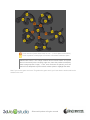
In particular, the capsule’s position relative to the actor’s 3D mesh must be specified so that the
capsule matches as closely to the mesh as possible; this way, the actor will collide with objects in
the world when we see them appear adjacent (i.e. in collision) with each other. The numbers that
work well for the Trog model are 0.00/1.565/-0.18 for X/Y/Z. Aligning the capsule does take a
little bit of work, but if you use our numbers above or come up with your own, you should see the
yellow bounding capsule that represents the physics collision volume matching closely with the
actor’s 3D mesh like this below:
© Dassault Systèmes. All rights reserved
Also, be sure to click the “Track Events” property to be true. We’ll need this later when we discuss
how to pick up items in the world.
9. If you run your game now, you should see that Trog doesn’t pass through walls, but he also falls
over! This is because the gravity is interacting within our physical world as we expect it to, but we
also need to modify how we control Trog and have him move around so that he doesn’t fall over
like this. Essentially, we want him to collide with objects, but we also want to ensure that he’s
always standing up (i.e. his bones and muscles are working). We’ll fix that next.
We will add more physical interaction with objects like attacking monsters and handling combat in just a
bit. Additionally, we’ll cover how to pick up items and add them to the player’s inventory when Trog
collides with these pickup actors in the next step. However, before we do that we need to discuss how to
correctly place these objects, like keys and gemstones, in the world.
A DIFFERENT CHARACTER CONTROL
Earlier in the previous section, we coded up the schematic scripts to control Trog in the game world. We
did this to explore scripting and get you stronger in your understanding of scripting, but there is also a
behavior that is posted for download on the 3DVIA Explorer site that handles input rather well. Search on
“Character Controls” (be sure to view Behaviors) and you’ll see the following:
© Dassault Systèmes. All rights reserved
If you drag and drop this behavior onto your Trog actor, you can delete the Rotate and Translate scripts
that we built earlier in this section of the tutorial. You could leave those in, but it’s also useful to see
another implementation of the behavior, so in this tutorial we’ll proceed assuming you removed the Rotate
and Translate behavior scripts and added the CharacterController script; you’ll notice that the
CharacterController script uses members to allow the developer to program which key maps to each
activity (using members MoveForward, RotateLeft, RotateRight, and Jump). This is better than hardcoding these values (such as WASD as we did earlier) to improve the flexibility of the program. It also
allows the user to potentially select which keys he/she would like to do if the game developer adds this
capability. The CharacterController behavior is also superior to our earlier script for translate and rotate
because it allows the movement and rotate speeds to be set as members. You can see the improved,
member-based approach in the CharacterController below:
To make use of the improved CharacterController behavior:
1. Add the Character Controls behavior to Trog
a. Set the Movement Speed property to 10 (you can change this if you’d like, but 10 is the
default).
© Dassault Systèmes. All rights reserved
b. Set the Phy World (the physical world) to the Physical World of our game. This ensures
that the physics will be implemented properly with the character controls.
2. Remove/delete the Rotate and Translate scripts we wrote earlier.
3. Open the CharacterControls behavior to observe the script; examine how it works and notice the
flow, how the inputs are handled. One that we won’t actually need is the “jump” building blocks at
the bottom of the script. Delete the connector from the Start node to the beginning of the jump
area (the “Is Key Toggled” building block that uses the Jump key). We can disable this section of
script because our character will be implementing its jump behavior through the animation
controller script, therefore it’s not needed here.
If you run the game now with the new controller script added, it will work very similar to the previous
implementation, but you now have a more robust character controller that you could extend to utilize other
keys if you’d like.
DEBUGGING/VISUALIZING PHYSICS
If you’d like to see how the physics engine is working and see a visualization of the collisions and physics
interactions while the game is running, you can turn on a debugging option that will show the physics
interactions while you run the game. Select the actor of interest and then select the vkPhysicsRigidObject
component of this actor. Go down to the “Debug Flags” property of the component and click the “Edit…”
button; this will bring up a dialog window, and you can turn the RuntimeDisplay option on. Notice that the
AuthoringDisplay option is on by default, which is why you see the yellow bounding volumes around
actors that have a vkPhysicsRigidObject component.
When you run the game with this RuntimeDisplay option turned on, you’ll see a red volume around the
actor. You will also see blue lines showing the normal vectors of the collision points.
The following figure shows blue lines which show the normal vectors of where the collision occurred.
Notice that our collision capsule on Trog is hitting the ground of the Tunnel_Model, and as I move around,
it shows the path of where Trog has been over the past one or two seconds.
© Dassault Systèmes. All rights reserved
Of course, visualizing these physics interactions is for debugging only, so be sure to turn off the
RuntimeDisplay option when you ship your game…unless you’re trying to create a Tron-like game or one
that “breaks the fourth wall.”
FOR MORE INFORMATION
Physics is a detailed and important topic for modern game development. As such, 3DVIA has provided
many useful materials online for your use. For more information on physics within 3DVIA Studio, please
see
http://www.3dvia.com/studio/documentation/user-manual/physics.
For a detailed reference and description of the physics building blocks within 3DVIA Studio, please see
http://www.3dvia.com/studio/documentation/building-blocks/physics.
3DVIA supplies a nice, simple physics example to manage a car driving over terrain at
http://www.3dvia.com/studio/resource/articles/physics-car-tutorial.
You can also view a nice tutorial on how to implement a car racing simulation which involves physics at
http://www.3dvia.com/studio/resource/example-projects/build-a-racing-game.
Finally, there is also a nice tutorial that implements a “Breakout” brick destruction game and involves
physics at
http://www.3dvia.com/studio/resource/example-projects/build-a-breakout-game.
© Dassault Systèmes. All rights reserved
A PAUSE IN THE ACTION: MORE ON TEMPLATES, ACTORS,
AND COMPONENTS
Now that you have had some exposure to creating elements of our game level, let’s take this time to
delve a little deeper into what’s going on with some of the items in our level. At this point, we have added
Trog into the game world, added the level geometry (the cave walls and floors), implemented the controls
to move Trog around, and finally added the physics so that he doesn’t walk through walls.
Before we go further in developing our game, we need to take a moment to discuss the relationships
between actors, templates and components. We have one game world and one main character (Trog),
but we’re about to have “duplicate” items in our level. Since we’re about to add bombs and gems (our
pickup items) into the level, it would be a good idea to discuss the best way to accomplish this with as
little effort and programming as possible. 3DVIA Studio gives us an easy way of adding lots of duplicated
items into our scene without having to recreate each aspect of the item over and over again.
Back in Step 2 (Importing Resources into 3DVIA Studio) we discussed the static bomb model and how to
make a template out of this model we imported, but we didn’t discuss a lot of details of what was going
on. In this section, we’ll go into more detail and explain why templates are important.
To begin, please view the helpful video tutorial on 3DVIA’s Web site at
http://www.3dvia.com/studio/resource/tutorials/managing-art-assets-in-3dvia-studio/actors-templatescomponents.
Once you have viewed this tutorial, let’s discuss actors, templates and components in more detail below.
DETAILS
In the next few pages, we’ll discuss the difference between Actors and Templates and how to use each
effectively within 3DVIA Studio. We’ll also cover Components in detail and how to add them to actors and
templates.
ACTORS
When you place an element into a scene within 3DVIA Studio, it adds what’s called an actor into the
scene. You can visually see the actor within the 3D View and the actor appears within the stage’s list
within the Project Editor.
You can think of an actor as an element within the scene that has specific components or characteristics.
The actor contains information about a particular element within the scene and can be customized by
modifying its components and characteristics. Examples of characteristics of an actor could be the
position, size and orientation of the actor. For example, if we have a Trog 3D model in our scene, this
Trog actor has a Local Position (where the model is located in the scene), Local Angles (the orientation)
and Local Scale (the size of the model). The following figure shows part of the Property View for an actor
indicating that we can change the position, angles, and scale of the actor:
© Dassault Systèmes. All rights reserved
The important thing to understand about actors is that while they can share some things in common with
other actors of the same “type” (also known as template), each one is unique and individual. We can
adjust the characteristics on a per-actor basis. For example, if we were to place two Trog models into our
scene and place them at different locations and at different orientations, each of these actors would share
the model’s mesh (3D geometry) and texture information, but each actor would have its own X/Y/Z local
position and X/Y/Z local angles (orientation). Changing one would not affect the other since they are
independent of each other.
When we modify a characteristic of an actor within the scene (either within the 3D View or the Property
View), a small wrench icon appears in the left side of the property’s entry for the actor. This icon indicates
that this characteristic has been modified from its default value. The default value is set from the original
type from which the actor was created, so this wrench icon denotes any characteristic that’s been
changed from the originating type. As you can see from the following figure, I have modified the Local
Position’s X value to 20 (from the default 0), so the wrench icon appears for this characteristic.
As you have seen previously and also based upon this discussion, actors make up the key elements in a
scene. We use actors to create all of the visual parts of our scene, and actors can move about the scene
and interact. In our game, the Trog actor and camera is controlled by the keyboard input from the user, so
we’re consistently changing the Local Position characteristic/property of the Trog actor. We also have our
level geometry within the scene to allow our player character to move about the world and navigate
around walls and other obstacles.
We’d like to now add the other essential elements of our game world into the scene within 3DVIA Studio.
These include the bombs, gemstones and doors in the level. But whereas we only have one Trog actor,
we will have many instances of gemstones and many instances of doors and many instances of keys.
We’ll have more than one gemstone, for example. Since we have many copies of each of these elements,
it would be advantageous to somehow link them together so that they share common characteristics. In
this way, if we need to make a change to some aspect of the gemstone, for example, we’d like this
change to propagate to all occurrences of the gemstone in the level.
© Dassault Systèmes. All rights reserved
As a more concrete example, consider that we might have a characteristic called “Point Value” that
indicates how many points a gemstone is worth when Trog picks it up. We’d like the player’s score to
increase by this “Point Value” whenever Trog runs into such a gemstone. If “Point Value” is set to a value
of 100, then the player’s score will increase by 100 whenever Trog picks one up. Imagine we have got our
game up and running and the score goes up by 100 each time a gemstone is collected, and then we hear
from user feedback that this value just doesn’t seem right; perhaps players want more points to feel
they’ve accomplished something significant. We would then be tasked with changing the “Point Value” up
to 200 for each gemstone. We could go through our level and change the “Point Value” of each gemstone
in the level, but as you could imagine, this is not good for at least two reasons:
1. We could easily miss updating a gemstone and its “Point Value” would remain at the incorrect,
older value of 100.
2. We would have to laboriously iterate through perhaps MANY gemstones in the level—a repetitive
and mundane task that no one would like to do.
There’s a better way to pull all of this off, and it involves maintaining a relationship between actors and
the “base type” from which they’ve been derived. The concept of a template handles all of this quite nicely
for us in 3DVIA Studio and follows a very object-oriented approach to development. If you’re not familiar
with object-oriented design and development, no worries- we’ll explain templates next.
TEMPLATES
A template is a means by which we can reuse common components and characteristics among many
different actors. We can make a change to these actors in one, common place (i.e. within the template),
making these changes manifest among all actors. This follows good design practices in that we can
minimize the work we need to do to affect changes which will invariably show up in our projects.
IMPORTANT NOTE: Another advantage of templates is that they save
memory/space. Consider that our game only needs to load a template once
and then apply any configurations/changes on a per-actor basis. In this way,
we can have many instances of a template but only store what’s changed for
each actor. This is very efficient and is very important for Web-based games
in particular.
We say that an actor is an instantiation of a template when we use a template to create a new actor.
Another way of saying this is that an actor is an instance of a template when we create an actor from a
template. All of the characteristics and components of the template are present in any actor that is
instantiated from this template.
Realize that you can have many different templates, and each of these templates can be instantiated into
actors. In the case of our Spelunca game, we will have a template for the bomb, key, ruby gemstone and
diamond gemstone. We’ll then create multiple bomb actors from the bomb template, multiple key actors
from the key template, multiple ruby gemstone actors from the ruby gemstone template and multiple
diamond gemstone actors from the diamond gemstone template.
To illustrate the relationship between templates and actors, consider that we might have a template for
the bomb entity in our scene. We’d like to create three bomb actors from this template (i.e. instantiate the
© Dassault Systèmes. All rights reserved
template). One bomb actor will have no changes (and will not have any wrench icons present in the
Property View since nothing has been modified); another bomb is located in a different position, but no
other changes are made; and finally, the third bomb is repositioned and we set its “Is Lit” characteristic to
true indicating that the bomb is about to explode. If the default value for “Is Lit” is false, then this third
bomb’s position and “Is Lit” characteristic are different from the template, so both of these properties will
have the “has been changed” wrench icon present next to them. The relationship between the bomb
template and the three bomb actors is illustrated in the following figure.
The easiest way to create a template is to create an actor in the scene and set it up with the
characteristics and components that you want it to have by default. Then just right click on the on the
actor in the Project Editor and select “Create a Template” from the popup menu as shown in the figure
below:
© Dassault Systèmes. All rights reserved
Once the template is created, it will appear in the Project Editor under the Templates section as shown
below.
Templates are not visible in the compiled/running scene, but they do show up in the scene when
building/editing. To hide the template, just click the eye icon to the right of the template name in the
Project Editor. This eye icon toggles the visibility of the template in the scene while you build it. You can
see an example of this eye icon in the figure above. If your templates are visible in your scene and you
don’t want them to be visible, make sure you uncheck the “Present” box at the top level (“Templates”) and
this will make all templates become invisible in the scene.
To create actors from a template (i.e. instantiate the template), you can simply drag and drop the
template from the Project Editor into the scene. You’ll notice that the new actor is added into the stage
within the 3D View and also appears in the Project Editor.
The following figure shows three actors that have been instantiated from a Bomb template. Notice that the
Project Editor shows all of these entities and the 3D View only shows the actors since the “visible” icon
has been selected as off for the template.
© Dassault Systèmes. All rights reserved
IMPORTANT NOTE: If you click the template name within the Project
Explorer, all the actors that are instances of this template will be highlighted in
blue. This is a good, quick way to find all the instances of a template.
You can also click an actor in the Project Explorer, and if there is a template
from which the actor was created from, then the template will be highlighted in
green. This is a good, quick way to find out what (if any) template an actor
was instantiated from.
Once you have defined a template and have instantiated it into multiple actors within the stage, you can
modify the template and then all of the changes that you make to the template will be passed down to all
actors of this template. The changes you make will be passed down and you will see these changes
within the actors of this template when you select the “Apply Changes” option within the Project Editor.
You can apply changes by right clicking the template and selecting the “Apply Changes” option. This will
affect the changes on the actors for this template.
In the following figure, you can see that we have modified the Bomb template to use a different Material
(in this case, an emissive and ambient color of red). By modifying the template, we can make this change
to all the actors, i.e. there is no need to modify the actors individually—modifying the template is sufficient
to affect the change across all the actors. Notice that in the figure below, the Material Override property of
the Bomb 1 actor does not have the “has been changed” wrench icon since this property hasn’t been
changed in the actor--the color is different on the actor because the template was changed.
© Dassault Systèmes. All rights reserved
Of course you can still customize each individual actor’s characteristics. If you want to revert the
instantiated actor back to the template’s value for any characteristic, you can simply click the wrench icon,
and the modification will be removed so that the actor’s property will be the same as the template from
which it was instantiated.
IMPORTANT NOTE: If you would like to remove the relationship between an
actor and its template, you can right click the actor in the Project Explorer and
select “Template -> Make Actor Independent From Template.” This will
ensure that any future changes to the template will not be passed down to this
actor. While needed in some situations, you should use this option sparingly
as it defeats the purpose of templates (for the independent actors).
If you make a change to an actor that is based on a template and then want that “pushed up” and
implemented in the template, simply right click on the actor and select Template -> Update Template
From Actor. This modifies the template to match the actor. If you want the change to then be applied to all
actors that derive from that newly modified template, you need to right click the template and select
“Apply Changes…” as shown below:
© Dassault Systèmes. All rights reserved
By this point, you should understand that the relationship between templates and actors is quite powerful
and is a good design practice to follow. It can save you immeasurable time when you need to make a
change to a template and have that change propagate to the many instantiated actors of that template.
In addition to sharing characteristics/properties, actors can share components through the use of
templates. We’ll discuss that next.
COMPONENTS
Components are elements that can be added to an actor or template to extend its capabilities.
Components consist of members (variables) and behaviors (scripts or code). By defining a component as
an independent element, we can then add it to numerous actors that could all make use of the abilities
and members that make up the component. As a real-world example, consider that we might have a
component called FlyBe (that defines the behavior for flying). If this component had members for flight
speed, wingspan, flight height, etc., we could take this component and add it to actors such as Insect or
Bird. All the work that went into making the flying behavior work properly could be utilized automatically
by both the Insect and the Bird actors. Certainly, each of these actors could customize member
properties/values, so this shows that while components might define behavior and members, these are
also customizable on a per-actor basis.
Components show us another way in which object-oriented development practices can make our game
development task easier, since a lot of the work could be done beforehand. 3DVIA Studio provides a
means of sharing and resuing models, but it also provides a means by which we can make use of
components that we’ve written or that others have written.
Utilizing components is quite easy to do. We just locate them and drag them into the component ring of
our actor on the Property View space. You can also right click the actor and select “Add New Behavior” to
establish a new behavior in the component ring. We’ve already done this on the Trog actor, as you can
see from the figure belowshowing the Trog’s four components:
IMPORTANT NOTE: If you need to remove a component from the component
ring:
1. Right click the actor or template within the Project Editor and select
“Components.”
2. Move the mouse over the component that you would like to remove.
3. Select the “Remove Component: from X” (where X is the name of the
actor/template).
As we continue in building our game world, we’ll have an opportunity to make use of templates and
components quite extensively. Now that you know how to create templates from actors, how to customize
actors that are instances of templates and how to manage components, let’s continue our game
© Dassault Systèmes. All rights reserved
development by adding in torches and then pickup items like gems and keys and bombs. This will give us
an excellent opportunity to practice the good use of templates and also expand our understanding of
scripting. We’ll do this in the next steps.
FOR MORE INFORMATION
To learn more about actors, templates and components, please see the 3DVIA documentation at
http://www.3dvia.com/studio/documentation/user-manual/fundamentals.
You can also see step-by-step directions on creating a new template at
http://www.3dvia.com/studio/documentation/user-manual/creating-content/new-template-reusability.
© Dassault Systèmes. All rights reserved
STEP 7: SETTING UP TORCHES AND INTRODUCING PARTICLE
SYSTEMS
PRIOR KNOW LEDGE
You should understand how to create 3D Node actors and sub actors within the Project Editor.
IMPLEMENTATION
SETTING UP THE TORCH
Now that we have our cave established, let’s add some atmosphere to it. The next thing we’re going to do
is improve our lighting and add torches along the walls. These torches will contain a 3D model, light
source and a particle system (so that it looks like a flame is burning on the torch). In implementing this
torch, we’ll get to explore how to position items around our scene, how to work with particle systems and
how to utilize lighting effectively in 3DVIA Studio.
1. To begin, open the folder containing your assets and then open the stage subfolder (i.e. open
Assets -> Stage within your operating system’s file explorer).
2. Drag and drop the torch.dae file into the 3D View scene within 3DVIA Studio and confirm the
import in the popup dialog box that appears. Name the torch actor “Torch.”
3. Click on the new torch actor in the Project Editor and then switch to the Authoring Camera within
the 3D View and press ‘E’ to center on the torch.
4. Set the Local Scale property of the torch to 50 so that it’s at the appropriate size.
5. Change the Local Angles of the torch to be approximately 128/73/129 in the X/Y/Z so that it has a
slight tilt to it.
6. We will be making a template based on this torch actor very soon, so the exact position isn’t
really important, but for now, move it somewhere in the cave so that it looks like it’s approximately
on the cave wall somewhere in the cave.
Your torch should look something like this:
While the torch model is interesting and does show up if we move around our scene, it’s not very
believable since it doesn’t generate any light, and the “flame” portion of the model doesn’t move or look
© Dassault Systèmes. All rights reserved
like real fire. Let’s improve that next by adding a particle system to emit flame-like particles from that
orange part of the model.
ADDING THE PARTICLE SYSTEM
By default, when you add a particle system component to an actor, it will be oriented along the Z axis of
the geometry of the actor. If you want to make the orientation of the particle emitter of the particle system
different from this, first add a 3D Entity into the scene as a sub actor of the model/actor to which you want
to attach the particle system, then add the particle system component to this sub actor. You can then
orient the sub actor as needed to ensure the particle emitter is oriented the way you want.
To illustrate this, let’s imagine that we want to add a particle system to the torches in our scene so that
they look like there are embers/sparks coming up out of the fire portion of the torch model. If we were to
just add a particle system to the torch actor, then the particles would be emitted as if they were coming
horizontally out of the torch, not up from the top of the model. To correct this, we can do the following:
1. Add a 3D Entity to the scene (from Presets -> 3D in the Libraries view). Name it FirePS.
2. Add this FirePS actor as a subactor of the Torch in the Project Editor by dragging the FirePS
actor entry onto the Torch actor entry.
3. Ensure that the Local Position of the FirePS actor is 0/0.015/-0.006 in the X/Y/Z to center the
particle system on the orange portion of the torch model.
4. Change the Local Angles to be 75/0/0 in the X/Y/Z of the FirePS (this makes the particles emit
up)— we don’t want to set this vector to be 90/0/0 or the particles will be emitted along the torch’s
main vertical axis, which is slightly tilted so that it looks like it’s coming out of the wall. In fact, we
want the flame to go straight up, so this 75/0/0 vector works.
5. Add a Particle System component to the FirePS actor (select the Particle System from the
Presets -> Particle Systems entry in the Libraries view). Adjust the properties of the particle
system:
a. Set Birth Rate to 30.
b. Set Velocity to 0.75.
c. Set Velocity Variation to 0.5.
d. Adjust the “Color Over Life” properties to match the following:
This will make the particles start as red and transition to yellow over a 1 second
timeframe.
e. Set the Size to 100 and set the “Size Over Life” property to a vkLerpController (this is a
linear interpolation controller, so there will be a linear progression from start to end).
Expand the Size Over Life property and set the sub properties as follows: Duration to 1.0,
© Dassault Systèmes. All rights reserved
f.
the Start Value to 0.02 and the End Value to 0.0. This will make the particles get smaller
over time.
Set the “Size Variation” to 50 to allow some “spurts” of flame.
If you run the game and view the torch and particle system, you should see something much more
realistic in that the 3D model is positioned along the wall, and now there looks to be flame emitting from
the top portion of the torch model. As these particles within the flame rise, they get smaller and “cooler,”
shifting from red to yellow and then disappearing altogether. Feel free to experiment with various values
of the particle system component to get the look and feel you want for your torches. You can even
change the start/end colors to get a sci-fi look if you want to go from blue to purple for example!
ADDING A LIGHT SOURCE TO THE TORCH
Now that we have set up the particle system for the torch, let’s adjust lighting for shadows so that the light
actually looks like it’s coming out from the torch.
1. Add an Omni Light (found at Libraries -> Lights -> Omni Light) to the Torch actor by dragging it
into the scene (and confirming when the import dialog box shows) and the moving the new Omni
Light actor as a sub actor of the Torch. If you followed along with all of these activities, your
Project Editor should display the Torch with sub-actors FirePS and Omni Light as shown below:
2. Once the Omni Light has been added to the Torch as a sub actor, we’ll need to position it so that
it’s a little above and a little ahead of the torch (i.e. a little further from the wall). We do this so that
the light can emit out and also cast shadows properly. As you can see from the image below
(wherein the light bulb represents the Omni Light), you want your Omni Light to be above and in
front of the torch 3D model:
3. We also need to adjust the color properties of the light so that it fits in with the cave atmosphere.
To do this, set the color to be 1/0.5/0/1 for R/G/B/A, set the range to 30 and set the power to 2.
© Dassault Systèmes. All rights reserved
Your Omni Light properties should look like this:
4. On the Omni Light sub actor of the Torch, set the Cast Shadows property (located in the Shadow
section of the Property View of the Omni Light) to be eShadowMap. By default, this is set to null,
which means that the shadows won’t be generated and the light will pass through geometry (not
what we want!), so change this property to be eShadowMap to get the correct look for the light.
5. Since the torch is the source of our light, we should ensure that the geometry of the torch model
doesn’t interfere with the light. The best thing to do is set the torch geometry to not cast shadows,
i.e. don’t block the light coming from the torch. To do this, we need to set the Cast Shadows
Enabled property of the vkEntity3D of the torch to be false (i.e. uncheck the property). The
following images show what this looks like with the Cast Shadows true (left) and false (right)-notice the absence of the shadow on the wall in the image to the right. We don’t want shadows
for the torch model to show, so the false (right) view is correct. You will note that I’ve turned off
the ThreePointLighting lights (which illuminate the entire scene for development purposes), so
you can get an idea of what the cave would look like near the torch (and also so that the shadow
difference is more pronounced in the two images below).
6. If needed, position the torch so that it looks like it’s connected to the wall.
If you run your game and move close to a torch, you will see something like the following. Of course, in
your running game, it’ll look much cooler since the flame particles will be moving, changing size,
changing color and fading away.
© Dassault Systèmes. All rights reserved
IMPORTANT NOTE: Particle Systems are a very powerful way to add polish
and nice effects to your game. You should spend some time exploring how to
make use of particle systems within 3DVIA Studio, as there are many options
available to create impressive effects within your games.
MAKING THE TORCH PHYSICAL
At this point, we have created a Torch template that contained a 3D model, a particle system that
simulated flames, and an omni light to emit light over a certain area. There is only one more thing we
need to do before our torch is complete. We need to modify the torch so that Trog doesn’t walk through it
by implementing a physics bounding volume around the torch. Earlier when playing the game, you might
have noticed that if you walk up to a torch, Trog could actually pass through the 3D mesh/model. This
isn’t what we really want, so let’s add a vkPhysicsRigidObject component to the Torch template to
prevent this incorrect behavior of “walking through the flame!”
1. Add a Physics Rigid Object (found at Libraries -> Physics -> Physics Rigid Object) to the Torch
template.
2. Set the Shape property to vkPhysicsCapsule
3. Adjust the Delta Position to 0/0.003/-0.002 in the X/Y/Z to achieve the bounding capsule similar
to what’s shown below.
© Dassault Systèmes. All rights reserved
4. Set the Motion Type to Fixed (else the torch will fall to the ground! ).
Now if you run the game and walk up to a torch, you won’t be able to walk through it.
MAKING A TEMPLATE OF THE TORCH AND POSITIONING THEM IN THE CAVE
Now that we have the torch and its associated light and particle system implemented, we’ll create a
template that we can use later as we fill the cave world with light.
1. Right click on the Torch actor and select “Create Template.”
2. We’ll next add many torches to the world. Use the following figure as a guide to determine where
you should add torches; you can change your placement from the suggested positions if you’d
like. Be sure to place them in the world and orient them so that they look like they’re attached to
the cave walls.
© Dassault Systèmes. All rights reserved
Torch near door (leave these blank for now – i.e. don’t place torches here)
Torch at position to lead player to find item or illuminate maximum space
IMPORTANT NOTE: The orange markers above indicate where we’ll place
doors in the world (in the next step); right now, leave the positions marked by
these orange squares “empty.” Later, once the doors are placed, you’ll see
that we’ll use templates to place torches at these points to highlight the doors.
Now if you run the game and move Trog about the game world, you’ll see that the torches add a nice
realism to the cave.
© Dassault Systèmes. All rights reserved
If you want to test out the true nature of our new lights throughout the cave system, set the Power
property in the three sub actors (directional lights) of the ThreePointLighting element to 0.3. This is a
good value to get a nice level of ambient (global) lighting but still allow the torches to provide the most
light and cast shadows nicely.
FOR MORE INFORMATION
For more information on particle systems and their implementation in 3DVIA Studio, please see
http://www.3dvia.com/studio/documentation/user-manual/particle-systems.
© Dassault Systèmes. All rights reserved
STEP 8: BUILING THE SCENE PART 2: ADDING DOORS AND
PICKING UP ITEMS IN THE WORLD
PRIOR KNOW LEDGE
At this point, you should know how to position and orient actors within the world. You should also
understand the relationships between actors and templates. We also expect that you know how to create
a template from an actor, update a template and then propagate those changes to any actor that derives
from the template and make a change to an actor and then propagate the change made to the actor up to
the template from which it is derived.
IMPLEMENTATION
Now that we have our lighting and main cave geometry established, let’s set up some obstacles for Trog.
We’ll place doors to keep him confined to certain areas until he finds a key. This way, we create a natural
progression for Trog’s exploration. Let’s add the doors first, and then we’ll add the pickup items (such as
keys and bombs) so he can overcome these obstacles.
ADDING DOORS
Before we can add all of our items, such as keys, bombs and gems, we need to place some obstacles in
Trog’s way. The placement of these other pickup items will depend on how we segment the cave since
we want to limit where Trog can move until he finds and picks up the keys. The keys will allow him to
open doors, so the door placement will determine where to place the keys.
1. Begin by importing the “doorframe.dae”, “door_left.dae” and “door_right.dae” files into the project
by dragging them from the Windows explorer into the default stage of the Project Editor. These
are separate files since we may want to animate each of them independently, rotating each side
of the door to swing open on a different axis. Additionally, the doorframe shouldn’t move or
disappear while the game is running.
2. We’ll need to create a 3D Entity to hold the sub-actors that make up a door. To do this, create a
3D Entity (from Libraries -> 3D -> 3D Entity) and drag it into the DefaultStage of the Project
Editor. Rename the 3D Entity “Door”. Next, create another 3D Entity actor and call it “InnerDoor”.
Drag the Doorframe actor into the Door, making it a sub-actor of the Door. Drag the
Door_Group3_Door_Door_Left and Door_Group3_Door_Door_Right actors into the InnerDoor,
making them both sub-actors of the InnerDoor. Lastly, we’re going to want lights around the
doorframe, so we must do the following:
a. Add two Torch actors into the scene and make them sub-actors of the Door.
b. Rename these two Torch sub-actors DoorTorch and DoorTorch2.
c. Place them (changing their Local Position X/Y/Z) so they appear just above the doorway
on either side of the doorframe.
If you did everything correctly, then you should see the following in your Project Editor:
© Dassault Systèmes. All rights reserved
3. You’ll next need to set the Local Scale property to 100 for the Door actor (not the sub-actors), so
that all parts of the door are enlarged.
4. Position the InnerDoor relative to the Door so it looks like the door pieces align with the
doorframe, and position the Door actor so that it blocks the first tunnel leading into the main hub
(center) of the world. You should see something like this:
Very soon, we’ll establish templates based upon these actors and load the instances of the Door
and InnerDoor templates into our world; we’ll do this so that we can dynamically remove the door
when Trog opens it (with a key). When we instantiate the templates, we’ll set the positions and
rotation angles, so don’t worry if these things aren’t exact. We’re only getting these lined up now
for visualization and not functionality purposes.
5. Add a vkPhysicsRigidObject component to the Doorframe (not the Door) and mark its “Motion
Type” property to “Fixed”. You also need to specify that the vkPhysicsRigidObject shape property
is set to vkPhysicsMesh. This makes the doorframe solid so that Trog can’t walk through the
doorframe, but can walk through the hole in the middle. Your door should look like this (with the
physics rigid object shape highlighted around the doorframe):
© Dassault Systèmes. All rights reserved
We now have the doorframe created as a solid, physical object, and if you run your game, you
can walk up to, but not through, the doorframe. Unfortunately, you can walk through the door
itself, so now we need to handle the left and right pieces of the door.
6. Select the “Inner Door” actor and add a vkPhysicsRigidObject component to it. We want to
position the collision shape’s properties so that when Trog gets near the door, we can handle the
collision. We want this to happen when he’s near the door, not when his nose is touching the
door, so we need to adjust the collision space to be offset from the door’s geometry. We want
something like what’s shown below.
We can achieve this by setting the Shape property of the vkPhysicsRigidObject to be
vkPhysicsBox and the Shape -> Size property of the vkPhyiscisRigidObject component to be 2.0
in the X, 3.0 in the Y and 0.8 in the Z. We then set the Delta Position property of the
vkPhysicsRigidObject component to be 3.0 in the Y and -1.0 in the Z (X can remain 0). This will
give us the desired collision space that’s immediately in front of the door. You can adjust these
property values to obtain whatever collision space you desire.
7. Be sure to set the Motion Type of the InnerDoor to be Fixed.
8. Set the Track Events to be true on the vkPhysicsRigidObject component of the InnerDoor.
9. We need to add a behavior to the door so that it interacts with Trog correctly. We want the door to
open when Trog collides with the collision volume we just established. Of course, Trog needs to
be holding a key for the door to open, but we’ll worry about this detail later when we implement
© Dassault Systèmes. All rights reserved
the collision logic within Trog’s behavior. For now, create a behavior “doorBe” and add it to the
“InnerDoor” actor.
10. Add the following four members to the doorBe behavior, setting the types as shown:
11. Return to the Assemble tab and set the leftDoor and rightDoor members of the doorBe behavior
to refer to the left and right sub-actors of this Door actor.
12. Return to the Behaviors tab. We’ll add logic to the door similar to the logic implemented on the
pickup items. Create a new VSL function called “DisablePhysics” and add the following code to
this function:
void
doorBe::DisablePhysics()
{
vkPhysicsRigidObjectPtr phys;
phys = GetActor().GetHeadComponent().GetNextComponent();
if (phys)
{
phys.Destroy();
// SoundToPlay.Play();
}
}
The code above finds the vkPhysicsRigidObject component on the InnerDoor sub-actor and then
destroys this physics component. We do this because we don’t want there to be any more
physics interaction on the door itself, though we do want the doorframe to still have physics
enabled. We also play the sound associated with this script, though we’ll discuss the
implementation of sounds in the next step. The sound line is commented out since we’re not
using sounds just yet and if you leave it in, an error will occur and your game will “crash.”
13. Add another VSL function called “Remove” to the doorBe behavior. Add the following code to this
function:
void
doorBe::Remove()
{
GetStage().DestroyDynamicActor(GetActor());
}
The code above removes the Entity3D actors that represent the left and right door parts from the
game world so the door looks visibly open. You could add a more elaborate script here to swing
the doors open or rotate them on their axis, so please feel free to add this if you’d like. Our
implementation will keep things simple and just remove the doors from the world. This, coupled
with the removal of the physics component of the InnerDoor actor, will not only remove the door
visibly, there will also not be any physics interaction hereafter once the door is “unlocked.”
14. Finally, to finish the door opening script we must add a Schematic script. Add a Schematic script
function called “DoorHit” that starts by invoking the DisablePhysics function and then calls the
Remove function. Both of these are the functions we just wrote in VSL.
© Dassault Systèmes. All rights reserved
IMPORTANT NOTE: You can add a VSL function you wrote to a Schematic
function by simply dragging the VSL from the Functions tab (left-side) into the
Schematic workspace. This creates a new building block that will invoke the
VSL script.
15. Bind the scripts together using connectors, and your DoorHit function should look like this:
16. Now that we have our desired door and inner door structures, we can create templates from
these actors. Right-click the Door and InnerDoor actors in the Project Explorer and select “Create
a Template” for each.
17. The Local Position values for these door and inner door templates are probably some non-zero
value since we positioned them in the cave to get a feel for how they’d look and work. But we
want to set these positions when we create these doors, so set the Local Position and Local
Angles for the InnerDoor and Door templates’ X/Y/Z to be 0/0/0.
18. Finally, we need to create actor instances of the door template and position them in the world to
create unique, sub-divided spaces within the cave world. We want the doors positioned like the
following figure shows:
The red doors should have their locks facing in toward the center of the world, but the blue door
should have its lock facing the south area (since this is where Trog will begin his adventure). This
placement allows us to position items and enemies in the world and let the player explore the
game world and advance the game slowly over time. We could write an entire book on level
design (and many people have!), but this approach to our game world is sufficient. Since we’re
managing our doors dynamically, we want to place them with script, not actually add actors in
© Dassault Systèmes. All rights reserved
manually, so we’ll code up the script to add the doors programmatically (i.e. via script) next. For
now, don’t place doors down – we’ll let the code do that for us next.
19. We don’t need the Door and InnerDoor actors – we just need the templates, so remove these
actors from the scene.
20. Right-click on the Door and InnerDoor templates and accept changes for these templates.
DYNAMIC DOORS
While you could position your doors manually, we’ll need to delete the InnerDoors when Trog “unlocks”
them, and to do this, we need to work with dynamic actors.
Dynamic actors are like any other actor, except that they’re created as the game is running. This means
we need a way to instantiate a template at runtime (while the game is running), and then we can also
remove these dynamic actors during runtime (when Trog unlocks a door, for example). We’ll need to
create a lot of dynamic actors in our game (for all the gemstones, health hearts, bombs, lizards, etc.), so
let’s establish an entity in our game scene that is responsible for creating the dynamic actors and placing
them in the right spot. Initially (at this phase in the tutorial), we’ll run this when the game first begins, but
later, we’ll also use it when the game is reset (when Trog dies or wins and the player chooses to play
again).
1. Begin by creating a new 3D Entity (from Libraries -> 3D -> 3D Entity) and place it in the scene.
Rename it IntroControls in the Project Editor.
2. Add a new behavior called “IntroBe” to this IntroControls actor.
3. Create two members within this behavior, called “DoorBePtr” and “InnerDoorBePtr”, and make
them both type vkTemplatePtr.
4. Return to the Assemble tab and link the DoorBePtr to the template Door and the InnerDoorBePtr
to the InnerDoor template. We’ll use these template pointers/references in our script next to know
what type of dynamic actor to create.
5. Create a new VSL function called “SetupActors” and place the following code in this function:
// Definition of the function SetupActors
void
IntroBe::SetupActors()
{
vkVec3 door_positions[5];
door_positions[0] = vkVec3(-63.76091, 0, -21.86632);
door_positions[1] = vkVec3(-36.7457, 0, 43.5681);
door_positions[2] = vkVec3(35.4766, 0, 8.1884);
door_positions[3] = vkVec3(-8.6063, 0, -61.2785);
door_positions[4] = vkVec3(27.5473, 0, 57.2138);
float orientations[5];
orientations[0] = 0;
orientations[1] = -2.09;
orientations[2] = 0.61;
orientations[3] = 2.1;
orientations[4] = -0.06;
vkVec3 upVec (0, 1, 0);
vkNode3DPtr ptr;
for(int i=0; i < 5; i++) {
ptr = vkNode3D::ComponentCast(GetActor().GetStage().CreateDynamicActor("Door", this.DoorBePtr));
ptr.SetLocalPosition(door_positions[i], true);
ptr.Rotate(upVec, orientations[i]);
ptr = vkNode3D::ComponentCast(GetActor().GetStage().CreateDynamicActor("InnerDoor",
© Dassault Systèmes. All rights reserved
this.InnerDoorBePtr));
ptr.SetLocalPosition(door_positions[i], true);
ptr.Rotate(upVec, orientations[i]+0.22);
}
}
The script above utilizes arrays (a data structure) to store vectors and floats and then iterates
using the loop to establish ten new dynamic actors – five Doors and five InnerDoors. These
actors are then positioned and rotated so they are properly aligned with the cave tunnels. Where
did all these magic numbers come from? We correctly placed doors, oriented them to our liking,
recorded the positions and rotations, and then added them into this script so we could
dynamically create them later. We did all that work to save you time!
IMPORTANT NOTE: If you’ve adjusted the rotation of your tunnel model in
the scene, then these doorframes and doors won’t line up properly with your
adjusted/modified scene. To correct this, ensure that your Local Position and
Local Angles for the Tunnels_Model actor in your scene are both set to 0/0/0
in the X/Y/Z.
6. Create a new Task called “Controls” and drag-drop the Setup Actors building block into this
schematic, tying the building block to the start as shown below:
Now when the game begins, and the IntroControls actor begins, the Setup Actors function will
run, which is exactly what we want to happen since the Setup Actors script adds the doorframes
and doors dynamically into our scene.
If you run the game, you’ll notice that the doors do indeed work and inhibit the player from entering areas
unless he/she holds a key. We’ll discuss how to code up the key logic in a little bit, but before we do that,
let’s just assume that Trog has an infinite number of keys, and let’s test the logic of handling the
collisions.
7. Select Trog (the sub-actor of the MainCharacter actor) and open his characterBe script.
8. Add a VSL function called “CollisionHandler” to the characterBe script and set the Triggers to
“vkPhysicsCollisionEvent”. This ensures that the CollisionHandler function will run when a
collision occurs with Trog.
9. Add the following code into the CollisionHandler script:
// Definition of the function CollisionHandler
void characterBe::CollisionHandler(vkPhysicsCollisionEvent& iEvent)
{
doorBePtr obj1 = iEvent.collidable1;
doorBePtr obj2 = iEvent.collidable2;
doorBePtr d;
if (obj1)
d = obj1;
else if (obj2)
d = obj2;
if (d) {
if (!d.hasBeenHit) {
© Dassault Systèmes. All rights reserved
d.hasBeenHit = true;
d.DoorHit();
}
}
}
The script above obtains references to the two objects involved in the collision (naming them obj1
and obj2), and then tests to see if one of them is a door (if the doorBePtr assignment works, then
it is a pointer to a door). If the door hasn’t been previously collided with, then we handle it by
setting the hasBeenHit member of the door to true and calling the DoorHit function. Since 3DVIA
Studio runs so fast, we must ensure that we’re not responding to two collision events before the
first one is resolved. This is a common problem in computing and is called a “race condition”. A
“race condition” happens when we inadvertently access or handle something multiple times when
we only want to access it once.
Since we already defined the DoorHit function in the Door actor, it will then dispose of itself as we
previously scripted. And while this script we placed in Trog won’t be the final version (since we eventually
want to test for keys before unlocking the doors), it works as is, and we can run and test the game. When
Trog comes sufficiently close to a door, then the door will disappear from view and he can pass through it
Notice that the InnerDoor is what disappears, so Trog must still navigate through the doorframes (our
Door template) to get into new areas of the cave.
Be sure to remove/delete any Door and InnerDoor actors that remain in your scene (so that only the
templates remain), and then run the game. You should be able to have Trog walk near a door and have it
disappear like shown below. The left image shows Trog approaching the door (with collision debugging
on), and the right image shows after he’s collided with the InnerDoor (with collision debugging off).
Now that we have working doors, lets add all the pickup items in our scene next.
CREATING THE PICKUP ITEMS (GEMSTONES, KEYS, BOMBS, AND HEARTS)
We’re now at a point where we can create our pickup items (keys, hearts, bombs, and gems). In addition
to the 3D mesh/visualization of the items, we need to add behaviors to make them interact in the game
world.
To add the pickup items, the first thing we need to do is add the models/assets into our scene.
© Dassault Systèmes. All rights reserved
1. Do this by dragging the dae files for the key, bomb, diamond, ruby, and heart into the scene and
name them each “key”, “bomb”, “diamond”, “ruby”, and “heart”. These dae files are located in the
Assets -> Stage folder of the assets that we provide to you.
2. Set the Local Scale of the Bomb to 300; set the Local Scale of the Diamond, Ruby and Key to 50;
and set the Local Scale of the Heart to 30. Again, depending upon whether you have control over
your asset creation pipeline, ideally these would all be scaled when created in the 3D modeling
tool, but just as in this case, sometimes you have to adjust the scale relative to objects in your
scene since they were created with difference source scales.
3. Position these pickup items so that they’re in an open space within the cave near Trog. This way,
Trog can see the items, and we can test his ability to pick them up. As you can see from the
image below, we have the items sized and positioned nicely, so we can now begin scripting their
behavior. Eventually, we’ll make a template based upon these actors and then dynamically place
them in the world.
Now that we have actors of each pickup type, we’ll add capability to them that is common to all. They
should each respond when Trog collides with them – though they’ll each act slightly differently. For
example, Trog will collect the gemstones no matter what when he collides with them, but he’ll only pick up
a health heart if his health is less than 100%, and he’ll only pick up a bomb if he’s holding less than the
maximum bombs he’s allowed to hold. Let’s implement this common behavior now:
4. Create new behavior pickupBe by right-clicking on the DefaultStage in the Project Editor and
selecting “New…”. In the dialog box that opens, select “Behavior Template” and type “pickupBe”
for the Name. You can leave the No Default Task selected as we’ll build the scripts shortly.
5. Create SubType (Enum Type) called PickupTypeEnum by double-clicking the “<New Type>” in
the SubTypes section of the Behaviors panel that appears. Select “Enum Type” and name it
“PickupTypeEnum” as shown below:
© Dassault Systèmes. All rights reserved
IMPORTANT NOTE: Enumerations are an easy way to keep track of different
values. In this case, we have five different types of pickup items, and we want
each of them to be associated with a numeric value (0-4) so that we can refer
to these names instead of the numbers in our script. This makes our scripts
more readable and understandable.
6. Add values called Ruby, Diamond, Key, Bomb and Heart (values 0-4). Do this by selecting the
PickupTypeEnum and then using the editor window in the middle of the 3DVIA Studio
environment to enter the name and value pairs. If you’ve done this correctly, you should see this:
7. Click the “Apply” button to finish creating the enumeration.
8. Create new member “PickupType” of type pickupBe::PickupTypeEnum
9. Create a new member “SoundToPlay” of type vkSoundPtr. We’ll discuss what to do with this
member in the next step, “Adding Sounds.”
10. Create new member “hasBeenHit” of type Boolean (to be used later)
IMPORTANT NOTE: When you create a member of a behavior, you might
notice that in addition to the Name, Type and Value fields, there is also an “S”
column on the right side of the Members table. If you click this true, the
member will be “static” or shared among all actors that have the behavior. In
the case of our game, we want each object to be independent, and each one
should track its hasBeenHit member separately, so DON’T mark this “S”
(static) column true- leave it off, which is its default value.
If you did all the above three steps correctly, the Members section of the pickupBe behavior
should look like this:
© Dassault Systèmes. All rights reserved
Notice that the enumeration type that we created and set as the type of the PickupType allows us
to use Ruby, Diamond, Key, Bomb and Heart as the value choices, which is exactly what we’d
like to be able to do!
11. Click “apply” to make the members part of the behavior.
12. Create a new Task called “Rotate” as shown below (details on how to complete this are also
below the image in case you need a reminder for some of these steps, though it’s very similar to
the rotate script we had for Trog earlier).
a. Control-double-click in the schematic script area and type “per second” to search for the
“Per Second” building block. Double click on this block, and set the value to 2.
b. Control double click in the script area and type “rotate” to search for the “Rotate” building
block.
c. Attach the Start to the in on Per Second and the out from Per Second to the in on Rotate.
d. Open the Target tab and add a new member called “skeleton” that is of type
“vkNode3DPtr”. Click “apply” and close the Target tab.
e. Click and drag out the first input (top left) for the Rotate building block and select the
“skeleton” local member we just created. Do the same for the fourth input of Rotate
(setting it to “skeleton”).
f. Attach the output from Per Second to the third input on Rotate.
g. Set the rotation axis to 0/1/0 in the X/Y/Z by double-clicking the Rotate block and setting
the values.
h. Connect the out of Rotate to the in of Per Second so that the script runs indefinitely (i.e. it
never ends).
13. Return to the Assemble tab and add the pickupBe behavior to each of our bomb, key, diamond
and ruby actors. You can find this newly-created behavior (which hasn’t been added to any actor
yet) by opening the “Resource Explorer” tab and then opening Template -> Behavior Template.
© Dassault Systèmes. All rights reserved
14.
15.
16.
17.
You’ll then see the pickupBe behavior there, and you can drag and drop it onto each actor that
you want to have the behavior.
Next set the PickupType member of each actor’s pickupBe behavior appropriately to match the
type of actor that the script is attached to. For example, set the PickupType to be “Bomb” for the
Bomb actor.
You’ll notice that there is a pickupBe entity in the DefaultStage that’s “all alone” and isn’t
associated with any actor. This was created when we right-clicked on the DefaultState and added
the behavior, but since we can always access this behavior through the Resource Explorer ->
Template -> Behavior Template route, just delete this stand-alone pickupBe from DefaultState to
keep our scene “clean.”
Add vkPhysicsRigidObject to each pickup type actor (Ruby, Diamond, Key, Bomb and Heart)
a. Adjust the Shape property to be vkPhysicsBox and the Size of the Shape to be 0.5 in all
dimensions (X, Y and Z), so that we have a nice area with which Trog can collide. You
could make this slightly smaller (and you’ll notice that this collision area is larger than the
object), but we don’t want players to have to be too precise in picking up items or this
gets tedious for the player and makes the game less fun.
b. Set Motion Type to Fixed so that the objects don’t fall due to gravity – we want them to
float in place.
If you leave off the vkPhysicsRigidObject, then the pickup behavior will be on the actor, but the
gem/key/bomb actor won’t actually be physical, meaning the character will just pass straight
through it, and the collision will never be registered. This means that the pickup script will never
be executed, so don’t forget to add the vkPhysicsRigidObject component!
Return to Behaviors tab and create a new VSL function called “Remove” that is a part of the
pickupBe behavior. The code is the same as it was for the inner door Remove script:
void
pickupBe::Remove()
{
GetStage().DestroyDynamicActor(GetActor());
}
Notice that GetActor() is needed since we’re in the behavior component within this script and
“this” (which refers to the current context of the script) isn’t the actor, but rather the behavior
component.
18. Create a VSL function “DisablePhysics” within the pickupBe behavior and add the following code:
void
pickupBe::DisablePhysics()
{
vkPhysicsRigidObjectPtr phys;
phys = GetActor().GetNextComponent();
if (phys)
{
phys.Destroy();
}
}
19. Create a schematic script task called “RemoveFromWorld” and set it up as shown below. More
details on how to accomplish this are also provided below the figure.
© Dassault Systèmes. All rights reserved
a. Drag and drop the Disable Physics function into the schematic script area and link the
start to the in of this building block.
b. Control double click and type “linear” to search for the “Linear Progression” building block
and add it to the schematic script. Link the out of Disable Physics to the in of Linear
Progression.
c. Set the values for Linear Progression by double clicking the block and setting the values
to 1000/1/0. This will make the progression go from 1 down to 0 over a one second
period of time.
d. Create a “Set Opacity” building block and link the bottom out of Linear Progression to the
in of this new Set Opacity building block; this path will be taken so long as the linear
progression hasn’t reached its end time (i.e. this is the path that will run as the linear
progression is moving from 1 down to 0). Link the out of Set Opacity to the bottom in of
Linear Progression.
e. Open the Target tab and add a new member called “entity” that is of type “vkEntity3DPtr”.
Click “apply” and close the Target tab.
f. Click and drag out the first input (top left) for the Set Opacity building block and select the
“entity” local member we just created.
g. Link the second output from the Linear Progression to the second input of Set Opacity.
This means that the value going from 1 to 0 will be the opacity level of the pickup item as
time progresses (i.e. it will slowly disappear over a one second timeframe).
h. Drag and drop the Remove function into the schematic script and link the top out of
Linear Progression to the in of Remove. This means this path will be taken once the
linear progression has cycled to its end time.
20. Since we don’t want the RemoveFromWorld to occur until Trog collides with the pickup item, we
need to mark this script as inactive. Do this by unchecking the mark next to the task name as
shown below:
Make sure this is unchecked.
21. Create a schematic function called “CharacterHit” as shown below and with details below the
image:
© Dassault Systèmes. All rights reserved
a. Control double click and search for and add a new building block for “Start Task”.
b. Connect the start to the in of the Start Task block.
c. Click and drag out and select the first input for Start Task; select pickupBe so that this is
the first input for the Start Task block.
d. Double click the Start Task block and then set the Task Proto value to be
pickupBe::RemoveFromWorld. This means that the Start Task block will invoke the
RemoveFromWorld script when this script is executed.
While quite simple, this function is needed because it is public outside the script and can be invoked
elsewhere. In fact, we’ll use this script within the character Trog’s script. Also, it’s useful to see how to
invoke/call other scripts from within schematic scripting, and the “Start Task” building block is useful to
know.
The scripts above allow us to remove the items from the world, but something must occur before the
CharacterHit function is run/activated. Invoking this CharacterHit function is the job of Trog, so let’s briefly
test it with some temporary scripting.
IMPORTANT NOTE: Often, developing a game is a very non-linear process;
you first must establish the actors and then add behaviors to them. In this
step of the tutorial, we’ll establish all of the actors/templates and then later, in
the next step, we’ll invoke the functions we’re defining here. This is in keeping
with the object-oriented game design philosophy that 3DVIA Studio enables
and is a good approach to take so that every element within the game
handles things appropriately.
To test our pickupBe scripting and ensure the items disappear from the world when Trog runs into them,
make the following modification to the CollisionHandler VSL script in the characterBe behavior on Trog.
This code isn’t the best in that we’ll improve it to be more modular (i.e. better coding), and we’ll also
extend it later to handle the inventory of Trog better.
22. For now, type this in to the CollisionHandler script (the bold code is what’s been added/modified):
// Definition of the function CollisionHandler
void characterBe::CollisionHandler(vkPhysicsCollisionEvent& iEvent)
{
doorBePtr obj1 = iEvent.collidable1;
doorBePtr obj2 = iEvent.collidable2;
doorBePtr d;
// test to see if we've hit a door
if (obj1)
d = obj1;
else if (obj2)
d = obj2;
if (d) {
if (!d.hasBeenHit) {
d.hasBeenHit = true;
d.DoorHit();
© Dassault Systèmes. All rights reserved
}
}
// *****************************************************************
// everything below has been added to allow for testing item pickups
// *****************************************************************
else
{
pickupBePtr objp1 = iEvent.collidable1;
pickupBePtr objp2 = iEvent.collidable2;
pickupBePtr p;
// test to see if we've hit a pickup object
if (objp1)
p = objp1;
else if (objp2)
p = objp2;
if (p)
{
HandlePickupCollision(p);
}
}
}
void characterBe::HandlePickupCollision(pickupBePtr& p)
{
if (!p.hasBeenHit)
{
switch(p.PickupType)
{
case pickupBe::PickupTypeEnum::Bomb :
p.hasBeenHit = true;
p.CharacterHit();
break;
case pickupBe::PickupTypeEnum::Key :
p.hasBeenHit = true;
p.CharacterHit();
break;
case pickupBe::PickupTypeEnum::Diamond :
p.hasBeenHit = true;
p.CharacterHit();
break;
case pickupBe::PickupTypeEnum::Ruby :
p.hasBeenHit = true;
p.CharacterHit();
break;
case pickupBe::PickupTypeEnum::Heart :
p.hasBeenHit = true;
p.CharacterHit();
break;
}
}
}
If you save and run your game, you should be able to run into the test pickup items and see them
fade/disappear when Trog runs into them. The code we have above isn’t the final version, but it’s a good
start to show how we’ll let Trog’s collision handler script inform the items that they should run their
CharacterHit script (which in turn fades the objects, removes their physics and then destroys them from
the world).
IMPORTANT NOTE: You might notice that we’re removing dynamic actors via
the DestroyDynamicActor method within the pickupBe’s Remove script. How
can it be that we’ve statically created the pickup actors, yet we’re treating
them like dynamic actors within our script? This gets into the low-level
memory models of 3DVIA Studio, and you’d be right to say this isn’t the
proper way of achieving or goal. Note that we’re just using these static actors
© Dassault Systèmes. All rights reserved
temporarily to test our script. We’ll very quickly fix this and shift into dynamic
placement of pickup items.
Now that you have the pickup actors for the diamond, ruby, key and bomb defined, we need to create a
template for each and drop many instances of these templates around the world. At this point, each
should have the pickupBe and vkPhysicsRigidObject components as shown below:
23. Right-click on the bomb actor in the Project Editor and select “Create a Template” (see the earlier
section titled “A Pause in the Action: More on Templates, Actors, and Components” if you forgot
how to do this).
IMPORTANT NOTE: You might already have a bomb or other pickup item
template (from our earlier exploration of templates all the way back in step 2
of this tutorial). If this is the case (which it should be if you’re following along
with our guidance exactly), just delete that old bomb or other pickup item
template prior to making this current actor that you just built into a template.
Delete the old bomb template, and then right-click the bomb actor and select
“Create a Template”.
24. Create a diamond, ruby and key template using the same technique – right-click and select
“Create a Template”.
25. Remove the temporary actors based upon these pickup templates. We’ll add the pickup items
dynamically next.
DYNAMICALLY POPULATING THE GAME WORLD WITH ITEMS
Now that we have established the main geometry of our game world, placed the doors (segmenting the
level into various spaces) and created templates for all the pickup items, we can add the pickup items into
the world. The keys will need to be placed carefully so that we can limit where Trog moves, since he’ll
need a key to unlock each of the doors we’ve placed. The gems can be placed wherever you like, but it
would be a good idea to balance where they’re placed so each different “zone” in our game world has
approximately the same number of gems. As for bombs, we should place them so there are enough
bombs for Trog to pick up and use against the lizards, but not too many or the game will be too easy.
Let’s add these pickup items into our world now. We’ll place all of these items as dynamic actors in a
script in just a minute, but first, let’s discuss the rational for where the items should appear. We’ll provide
a suggested pickup object placement map below. Here are some considerations that define our
placement of items:
Adding too many bombs might make the game too easy, but adding too few might make the
game too hard (or impossible) to finish.
It’s not as critical to balance the number of gems around the world since picking them up only
adjusts the score of our game and doesn’t affect the difficulty of the game. Be aware- the total
© Dassault Systèmes. All rights reserved
number of gems placed affects the total points possible in the game. If you want Trog to pick up
all the gems before he wins the game, then you need to remember the total possible score
(based upon the total gems in the world).
Key placement is a bit trickier, since each key will unlock a door, and we want to control how the
user progresses through the level. Keys must be placed at important points in the game world.
You can see from the map below where we’ll place keys, and where we suggest you place
bombs. You might want to place a few extra bombs near Trog’s starting point so that he has lots
of ammo with which to practice throwing.
KEY
BOMB
Now that you have an idea of the decisions for item placement, we’ll cover the script to dynamically place
items in our game world. We have the same problem that we had before with doors – if we want to
dynamically remove them from the world, then we must dynamically place them into the world.
IMPORTANT NOTE: We handle dynamic and non-dynamic actors differently
in scripts. Non-dynamic actors are removed from the game using the
Destroy() function, whereas dynamic actors are removed from the game using
the DestroyDynamicActor() function.
1. Switch to the Behaviors tab and open the IntroBe behavior. We’ll be modifying this to include the
dynamic placement of pickup items.
© Dassault Systèmes. All rights reserved
2. Add the following members to the IntroBe behavior: BombBePtr, KeyBePtr, HeartBePtr,
RubyBePtr and DiamondBePtr. Set the type of all of these to be vkTemplatePtr. When you’ve
completed this, you should see something like this:
3. Click Apply.
4. Return to the Assemble tab and then set the values for the members you just defined. For
example, for the BombBePtr, set the value to refer to the Bomb template; for the KeyBePtr, set
the value to refer to the Key template.
IMPORTANT NOTE: You may find that you have more than one choice with
the same name when selecting values for these template members. For
instance, there might be two bombs that show up from which to choose.
You’ll notice that one is a reference to the 3D model/geometry, and one is a
reference to the template. Pick the template version, which will have an
mpxml extension and appear in the Sources/Templates folder. You can see
the location if you leave your mouse over the option for a few seconds, as a
popup note will show the details of the option. The incorrect option will have
an mp3d extension and will appear in the Sources/Models folder.
5. Return to the Behaviors tab and open the SetupActors VSL script. Modify this script to contain
this new code (to establish dynamic placement for the pickup items):
// Definition of the function SetupActors
void IntroBe::SetupActors()
{
vkVec3 door_positions[5];
door_positions[0] = vkVec3(-63.76091, 0, -21.86632);
door_positions[1] = vkVec3(-36.7457, 0, 43.5681);
door_positions[2] = vkVec3(35.4766, 0, 8.1884);
door_positions[3] = vkVec3(-8.6063, 0, -61.2785);
door_positions[4] = vkVec3(27.5473, 0, 57.2138);
float orientations[5];
orientations[0] = 0;
orientations[1] = -2.09;
orientations[2] = 0.61;
orientations[3] = 2.1;
orientations[4] = -0.06;
vkVec3 upVec (0, 1, 0);
vkNode3DPtr ptr;
for(int i=0; i < 5; i++) {
© Dassault Systèmes. All rights reserved
ptr = vkNode3D::ComponentCast(GetActor().GetStage().CreateDynamicActor("Door", this.DoorBePtr));
ptr.SetLocalPosition(door_positions[i], true);
ptr.Rotate(upVec, orientations[i]);
ptr = vkNode3D::ComponentCast(GetActor().GetStage().CreateDynamicActor("InnerDoor",
this.InnerDoorBePtr));
ptr.SetLocalPosition(door_positions[i], true);
ptr.Rotate(upVec, orientations[i]);
}
// *****************************************************************
// everything below has been added to allow for pickups placement
// *****************************************************************
vkVec3 bomb_positions[17];
bomb_positions[0] = vkVec3(-118.7607, 0.4718, -73.7937);
bomb_positions[1] = vkVec3(-118.7607, 0.4718, -75.876);
bomb_positions[2] = vkVec3(-120.3068, 0.4718, -74.968);
bomb_positions[3] = vkVec3(-118.7607, 0.4718, -19.2968);
bomb_positions[4] = vkVec3(-60.9412, 0.4718, -60.2167);
bomb_positions[5] = vkVec3(-47.3859, 0.4718, 44.5451);
bomb_positions[6] = vkVec3(-108.9501, 0.4718, 38.9964);
bomb_positions[7] = vkVec3(-94.4313, 0.4718, 86.2324);
bomb_positions[8] = vkVec3(-40.7042, 0.4718, 104.596);
bomb_positions[9] = vkVec3(36.1124, 0.4718, 98.1627);
bomb_positions[10] = vkVec3(40.7587, 1.0774, 166.9898);
bomb_positions[11] = vkVec3(58.1737, 0.4718, 29.1896);
bomb_positions[12] = vkVec3(111.507, 0.4718, -58.8224);
bomb_positions[13] = vkVec3(43.1359, 0.4718, 8.0368);
bomb_positions[14] = vkVec3(4.9856, 0.4718, -92.8168);
bomb_positions[15] = vkVec3(-11.8529, 0.4718, -165.8189);
bomb_positions[16] = vkVec3(-47.6812, 0.4718, -10.507);
vkVec3 key_positions[6];
key_positions[0] = vkVec3(-139.7855, 1.3457, -46.7607);
key_positions[1] = vkVec3(-36.1232, 1.3457, 111.0995);
key_positions[2] = vkVec3(11.1657, 1.3457, -24.1543);
key_positions[3] = vkVec3(-27.6161, 1.3457, -124.8996);
key_positions[4] = vkVec3(12.7523, 1.3457, 184.0867);
key_positions[5] = vkVec3(79.8397, 1.3457, -0.4792);
vkVec3 heart_positions[7];
heart_positions[0] = vkVec3(-93.3558, 1.8769, -57.5223);
heart_positions[1] = vkVec3(-87.5122, 1.8769, 17.2043);
heart_positions[2] = vkVec3(-25.6991, 1.8769, 10.752);
heart_positions[3] = vkVec3(4.9301, 1.8769, 140.4679);
heart_positions[4] = vkVec3(105.5705, 1.8769, -19.8085);
heart_positions[5] = vkVec3(29.6752, 1.8769, -127.4461);
heart_positions[6] = vkVec3(12.1533, 1.8769, 8.3511);
vkVec3 ruby_positions[16];
ruby_positions[0] = vkVec3(-112.7742, 1, -29.0109);
ruby_positions[1] = vkVec3(-112.7742, 1, -124.2055);
ruby_positions[2] = vkVec3(-119.5247, 1, 55.8703);
ruby_positions[3] = vkVec3(-123.4056, 1, 51.2976);
ruby_positions[4] = vkVec3(-116.7665, 1, 52.2803);
ruby_positions[5] = vkVec3(-11.7251, 1, 191.0836);
ruby_positions[6] = vkVec3(2.4645, 1, 192.3255);
ruby_positions[7] = vkVec3(11.1679, 1, 178.4516);
ruby_positions[8] = vkVec3(-2.2687, 1, 183.228);
ruby_positions[9] = vkVec3(94.0586, 1, -62.6129);
ruby_positions[10] = vkVec3(136.7268, 1, -39.3609);
ruby_positions[11] = vkVec3(115.9581, 1, 1.1955);
ruby_positions[12] = vkVec3(-40.8301, 1, -111.4552);
ruby_positions[13] = vkVec3(44.3779, 1, -79.9148);
ruby_positions[14] = vkVec3(69.9324, 1, -168.6542);
ruby_positions[15] = vkVec3(20.314, 1, 26.8099);
vkVec3 diamond_positions[21];
diamond_positions[0] = vkVec3(-101.0215, 1, -129.2374);
diamond_positions[1] = vkVec3(-113.7094, 1, -27.949);
diamond_positions[2] = vkVec3(5.2135, 1, -108.4556);
diamond_positions[3] = vkVec3(-33.8098, 1, -189.804);
diamond_positions[4] = vkVec3(2.2887, 1, -202.6255);
diamond_positions[5] = vkVec3(46.3059, 1, -76.773);
diamond_positions[6] = vkVec3(78.0361, 1, -35.0092);
diamond_positions[7] = vkVec3(105.266, 1, 28.0653);
diamond_positions[8] = vkVec3(108.3967, 1, 24.6729);
© Dassault Systèmes. All rights reserved
diamond_positions[9] = vkVec3(-6.3107, 1, 185.6294);
diamond_positions[10] = vkVec3(-2.3422, 1, 197.4101);
diamond_positions[11] = vkVec3(10.9653, 1, 114.5235);
diamond_positions[12] = vkVec3(96.0545, 1, 155.562);
diamond_positions[13] = vkVec3(84.8734, 1, 118.8458);
diamond_positions[14] = vkVec3(-66.216, 1, 56.3189);
diamond_positions[15] = vkVec3(-52.973, 1, 114.1625);
diamond_positions[16] = vkVec3(-112.354, 1, 83.6223);
diamond_positions[17] = vkVec3(-74.2385, 1, 20.5298);
diamond_positions[18] = vkVec3(-87.9618, 1, 55.0721);
diamond_positions[19] = vkVec3(-1.5978, 1, 25.2053);
diamond_positions[20] = vkVec3(-66.216, 1, -85.4321);
for(int i=0; i < 17; i++) {
ptr = vkNode3D::ComponentCast(GetActor().GetStage().CreateDynamicActor("Bomb", this.BombBePtr));
ptr.SetLocalPosition(bomb_positions[i], true);
}
for(int i=0; i < 6; i++) {
ptr = vkNode3D::ComponentCast(GetActor().GetStage().CreateDynamicActor("Key", this.KeyBePtr));
ptr.SetLocalPosition(key_positions[i], true);
}
for(int i=0; i < 7; i++) {
ptr = vkNode3D::ComponentCast(GetActor().GetStage().CreateDynamicActor("Heart", this.HeartBePtr));
ptr.SetLocalPosition(heart_positions[i], true);
}
for(int i=0; i < 16; i++) {
ptr = vkNode3D::ComponentCast(GetActor().GetStage().CreateDynamicActor("Ruby", this.RubyBePtr));
ptr.SetLocalPosition(ruby_positions[i], true);
}
for(int i=0; i < 21; i++) {
ptr = vkNode3D::ComponentCast(GetActor().GetStage().CreateDynamicActor("Diamond", this.DiamondBePtr));
ptr.SetLocalPosition(diamond_positions[i], true);
}
}
The code above works very similarly to the placement of dynamic doors. We set up an array to refer to
the 3D point (vector) where we want to place the pickup items, and then we loop through and place them
at the designated positions. We do this for the bomb, key, heart, ruby and diamond types.
Again, perhaps you’re asking where we came up with all of these numbers. We placed the objects in the
world where we wanted them, then recorded the 3D vector positions of the objects. Finally, we
transcribed all of these points into the arrays in the script you see above. You could follow the same
approach if you wanted to move the objects around to different spots in the world.
If you save and run your game, you can see that Trog can move about the world and run into the items;
when he collides with them, they’re removed from the world as we’d expect.
Our game’s coming along nicely! But while it might look visually impressive, it’s like a classic silent film –
there’s no music or audio in the game at all. Certainly this wouldn’t do for any modern game, so let’s add
the music and audio in the next step.
FOR MORE INFORMATION
For more information on dynamically creating actors in a scene, please see
http://www.3dvia.com/studio/documentation/building-blocks/narrative/actor/create-dynamic-actor
© Dassault Systèmes. All rights reserved
STEP 9: ADDING SOUNDS
PRIOR KNOW LEDGE
This step assumes you’ll make use of the sounds we provide to you in the assets for this tutorial or you’ve
created your own sounds to use. We also assume that you have created the pickup and door scripts with
members of type vkSoundPtr, so we’ll make use of those in this step below.
IMPLEMENTATION
In this step, we’ll create a sound stage that contains actors that represent all of the sounds that we’d like
to play within our game. Other actors (such as the pickup items, doors and lizards) will then tell the
sounds to play when we want the event-driven sounds to play.
You will notice in the implementation below we only have one instance of each sound. We can refer to
these instances many times in various places within our game’s entities, but only need one occurrence of
each sound. It would be a waste of resources to instantiate them more than once each, and the approach
we take herein is good object-oriented design.
1. Begin by creating a new stage called “SoundStage”. You can do this by right clicking the
“Permanent Stages” element within the Project Editor on the Assemble tab.
2. Select the sound files that you want to import into your game from the Windows file system
(under the assets folder of this tutorial) and drag them onto the SoundStage element within the
Project Editor. All of these sounds will then be added to the Resources of the stage.
3. Add a “Sound Player” actor into the SoundStage by selecting Libraries -> Sound -> Sound Player.
Rename this actor “SoundDoor” and set its “Sound Resource” member to refer to the
“door_creak” resource. This binding establishes that when we tell the SoundDoor to play its
audio, it’ll play the sound resource/asset “door_creak”.
4. Repeat step 3 for each of the sound resources you imported. When you finish adding these, they
should be named as shown below:
At this point, we now have entities within our game that we can call upon to play sounds, but we
still need to make use of these sounds.
5. If you recall, we added a member to the doorBe behavior of the InnerDoor actor. Now that we’ve
established our sound entities, we can return to the doorBe and make the link between the
© Dassault Systèmes. All rights reserved
SoundToPlay member and our newly-added sound entity called “SoundDoor”. Browse within the
Project Editor until you find the InnerDoor template. Select the doorBe component (though remain
in the Assemble tab). Using the drop-down option on the SoundToPlay member, select the
SoundDoor entity as shown below:
6. Be sure to right click and “Apply Changes” on the InnerDoor template to ensure the SoundToPlay
member’s value is updated in the template. If you fail to do this, then the template hasn’t been
fully updated and the dynamic actors built from this template won’t have the sound properly set.
Therefore, the game will crash when the sound tries to play!
We’ve already written the script to play the sound when the door is opened (i.e. when Trog is holding a
key and collides with the door’s collision volume). Now that we’ve established this link using the
SoundToPlay member, the sound will play when the door is opened. As a review, recall that this is the
script code we placed on the doorBe behavior:
void
doorBe::DisablePhysics()
{
vkPhysicsRigidObjectPtr phys;
phys = GetActor().GetHeadComponent().GetNextComponent();
if (phys)
{
phys.Destroy();
SoundToPlay.Play();
}
}
© Dassault Systèmes. All rights reserved
Please note that you don’t have to rewrite this – we’re just referring to it here to show how easy it is to
play a sound. We simply invoke the Play() function of the SoundToPlay member, and the correct sound is
played.
7. You will need to uncomment the SoundToPlay.Play() line of script in the DisablePhysics function.
This line was commented out before since we didn’t have the sound set up properly. Now that
we’re doing the setup, make sure the line of code is enabled (i.e. remove the // before the code).
We’ll use this technique of associating members to sounds within our pickup items and the lizard. The
sounds will be played when Trog picks up an item, when the lizard sees Trog, attacks Trog, or when the
lizard dies.
If you run your game, you’ll hear a cacophony of sound when the game begins. This is because all of our
sound entities in the SoundStage are set to play when the game starts! We don’t want this.
8. Go back to the SoundStage and deselect (i.e. remove the checkbox) the “Active at Present”
option for each of the nine sound entities in this scene.
Now if you run the game, go over to a door and walk through it, a creaking door sound will play when
Trog collides with the door.
In the next step, we’ll make use of some of the other sounds we have in our SoundStage as we handle
collisions. Later we’ll utilize the lizard sounds when we discuss combat, and the behavior of the lizard.
ENABLING THE SOUNDS ON PICKUPS
Let’s now add the sounds on the pickup items so the correct sounds will play whenever Trog collides with
one. We won’t make use of the SoundToPlay member on our pickup items in this step, but in the next
step, we’ll define a behavior on the pickup items that includes a function called HandlePickupCollision
that will make use of a SoundToPlay member. For now, let’s establish the links to the correct sounds on
our pickup items.
1. Browse to the template for the bomb in the Project Editor and select the pickupBe behavior of the
bomb template. Set the SoundToPlay member to refer to the SoundBombPickup sound entity.
2. Repeat step 1 for the diamond and ruby templates, making their SoundToPlay member refer to
the SoundGemPickup.
3. Repeat step 1 for the key template, making its SoundToPlay member refer to the
SoundKeyPickup.
4. Repeat step 1 for the heart template, making its SoundToPlay member refer to the
SoundHeartPickup.
5. Right click on each of these modified templates and select “Apply Changes…” so that each
instance of these templates will be updated in the game world.
We’ll make use of these SoundToPlay members when Trog collides with these pickup items in the world.
Similar to playing the door’s sound, playing the pickup sounds will simply involve calling the Play()
function.
Set the DisablePhysics script in the pickupBe behavior to be the following code (adding the
SountToPlay.Play(); line)
© Dassault Systèmes. All rights reserved
void
pickupBe::DisablePhysics()
{
vkPhysicsRigidObjectPtr phys;
phys = GetActor().GetNextComponent();
if (phys)
{
phys.Destroy();
SoundToPlay.Play(); // *** add this line of script ***
}
}
Now when you run the game, you should hear the pickup items sounds being played whenever Trog
collides with them. Each different pickup item will have a different sound, as defined by the SoundToPlay
property.
Next, let’s add some background music to our game to create a fun, somewhat whimsical atmosphere;
this background music will play continuously, which is a little different than doing event-driven audio (like
when we have a collision with a pickup item).
ADDING BACKGROUND MUSIC
No game is complete without a little background music. A good soundtrack adds polish and can actually
contribute to the mood of the game. Fortunately, adding music is a quick and straightforward process.
3DVIA Studio natively supports both Microsoft’s Wave file (.wav), as well as Ogg Vorbis files (.ogg). Of
course, .ogg files are highly compressed, so you may consider using this format to save space. This is
especially true given how large soundtrack files can be. For example, the .ogg file for our background
music for this game is 1.2mb; the .wav version of the same audio is 20 times larger at 24mb! For this
tutorial, we’ll be using the .ogg file format.
1. To import the soundtrack, drag the background music “Trog_Background.ogg” from the sound
directory onto the 3D stage.
Next, we’ll add a new Sound Player:
1. Under the Libraries tab, click on Sound.
2. Drag a Sound Player on to the Sound stage (in the Project Editor).
3. By default, the Sound Player will be called “New Sound”. Rename it to “BackgroundMusic” by
right-clicking on it.
4. With BackgroundMusic selected, use the “Sound Resource” drop down to select the
Trog_Background music.
5. Under the Playing heading, make sure that loop mode is checked. This will make the background
music repeat unless stopped (programmatically) later in the game. Note: it is OK to leave the
emitter as NULL.
6. Test the game by running it. You should hear some caveman-like music playing in the
background!
If you did the above steps correctly, then you should see something like this for the properties of the
BackgroundMusic:
© Dassault Systèmes. All rights reserved
FOR MORE INFORMATION
3DVIA Studio makes playing sounds quite easy to do! The 3DVIA Studio site has good background
information on how to incorporate audio into your application. You can find this information at
http://www.3dvia.com/studio/documentation/user-manual/sound/using-sound
and
http://www.3dvia.com/studio/documentation/user-manual/sound/creating-compressed-sound-assets
© Dassault Systèmes. All rights reserved
STEP 10: IMPROVING COLLISIONS AND INVENTORY
PRIOR KNOW LEDGE
You should know how to work with the PhysicsRigidObject component and must have established the
templates for the various items in our game world such as gems, keys, bombs and hearts.
IMPLEMENTATION
At this point, we’ve established the pickup items and doors in the game world so that when Trog collides
with them, some basic scripts run, make the items disappear from the world and sound plays. As we
indicated earlier, we need to “clean this up a bit” and make the script interact more broadly with the game
state – such as updating according to what Trog’s already carrying. For example, we only want a door to
open when Trog is carrying a key. Let’s improve the ability to handle the collision intelligently and make
the items respond correctly when Trog runs into them.
From an object-oriented perspective, it’s not up to the pickup item to react when Trog runs into it. Rather,
Trog should handle this interaction, because we want to update his inventory to either increase his score
(in the case of him running into a gem), pick up the bomb, pick up the key or increase his health stat (in
the case of him running into a heart). Also, we only want him to pick up a bomb if he isn’t currently
carrying his maximum number of bombs (we’ll assume he can only hold 5, but you could adjust this) and
only pick up a heart if his health isn’t 100%. These are game design decisions, so you’re certainly
welcome to deviate from these suggestions to customize this game to your liking.
ESTABLISHING TROG’S INVENTORY
Like in most games, we’ll need to track what our main character has picked up, i.e. what he’s holding.
This inventory management is so important in games that we could establish a separate actor in the world
(perhaps calling it “Inventory Manager”) or add it as a separate behavior to our Trog actor. You can
certainly do that and modify what we’re presenting here, but in this game we’re building, the inventory is
small enough that we can manage it with some members within the characterBe behavior of Trog.
1. To begin, select the characterBe behavior of the Trog sub-actor of the MainCharacter actor.
Switch to the Behaviors tab so that you’re viewing the members of this behavior.
2. While not necessary, it’s nice to organize/categorize our members within a behavior. This makes
them easier to work with in the Properties View within 3DVIA Studio. You can create categories
within the members section just like you add members and functions – simply double-click the
“New Category” row as shown below within the Members view. Create one called “Inventory”.
3. Within this newly-created Inventory category, add four new members and set their types and
values as shown below (notice the health is set to 1.0):
© Dassault Systèmes. All rights reserved
These members will enable us to track how many bombs Trog is holding, as well as how healthy he is (on
a scale of 0 to 1), whether he’s holding a key and how many points he’s earned by picking up gems.
4. Be sure to click the “Apply” button to ensure these members are available to the script. If you
forget to do this, you’ll get errors when you compile your script (in just a minute below).
As we just stated, a more complicated approach might be necessary if we had a more advanced
inventory. For example, many role-playing games allow you to move items around, place items within
bags/containers and mix items together. If your game has all of these features, you can create a more
advanced inventory entity in your game, but for Spelunca, maintaining the members above will suffice.
Now that we’ve established Trog’s ability to manage his inventory, let’s move on to handling the collisions
with items and updating inventory in a better way than we’ve done in the past.
HANDLING THE COLLISION
Previously, we’ve set up PhysicsRigidObject components on our doors and pickup actors in the game
world. We’ve also added a PhysicsRigidObject component to Trog’s actor; we know these objects interact
using the 3DVIA physics engine since we’ve witnessed Trog running into them, and in turn seen them
disappear. Now it’s time to update Trog’s inventory so that his score, bomb count and whether he has a
key or not are also updated upon collision with objects.
1. First, we need to get Trog to recognize that he must handle the collision. This is done by setting
the “Track Events” property of the kvPhysicsRigidObject component on our actor to be true. This
should already be the case, but we’re restating it here to be sure you’re clear this is vital for the
collision handling to occur correctly.
IMPORTANT NOTE: Be sure to set the Track Events property to be true on
the vkPhysicsRigidObject component of the Trog main character actor. This
ensures that the Trog actor will be notified upon collision, and we can then
add the script to handle specific collisions with items within the Trog actor’s
behavior. If this Track Events property is not set to true, then you won’t get
notification and our collision-handling scripts won’t run.
2. Switch to the characterBe behavior and let’s modify that function called “CollisionHandler.” This
should be a VSL script. As a reminder, the Triggers should be set to vkPhyiscsCollisionEvent.
© Dassault Systèmes. All rights reserved
This will make certain this function is invoked when something collides with the actor that
contains this behavior.
3. Now let’s rewrite the CollisionHandler in a better way. You can delete that entire script (though
you should see some similarities) and do it as we indicate below. Enter the following code into
this function:
void
characterBe::CollisionHandler(vkPhysicsCollisionEvent& iEvent)
{
if (!TestDoorHit(iEvent))
TestPickupHit(iEvent);
}
This function will test to see if Trog has run into a door or a pickup item. Now we just need to
code these TestDoorHit and TestPickupHit methods. You’ll notice that we’re taking a more
abstract, modular approach to our scripting now – which improves the readability and flexibility in
case you want to extend and improve it in the future.
4. Let’s test for a collision with a door first. Add the following into the same VSL script, placing this
code below what you just typed:
bool characterBe::TestDoorHit(vkPhysicsCollisionEvent& iEvent)
{
doorBePtr obj1 = iEvent.collidable1;
doorBePtr obj2 = iEvent.collidable2;
doorBePtr d;
if (obj1)
d = obj1;
else if (obj2)
d = obj2;
if (d && holding_key) // we’ve collided with a door and we have a key
{
HandleDoorCollision(d);
holding_key = false;
HUD.UpdateHUD(bomb_count, gem_score, holding_key, health);
return true;
}
return false;
}
void characterBe::HandleDoorCollision(doorBePtr& d)
{
if (!d.hasBeenHit)
{
d.hasBeenHit = true;
d.DoorHit();
}
}
The code above detects that Trog has collided with a door and is also in possession of a key, so
it informs the door it’s been collided with, removes the key from the inventory of Trog and then
updates the HUD (so that the key no longer shows in the HUD). We haven’t coded up the DoorHit
© Dassault Systèmes. All rights reserved
function within the pickupBe behavior, nor have we established the hasBeenHit member, thus
we’ll have to add those to the pickupBe behavior in just a minute.
The HUD.UpdateHUD() function call (near the end of the TestDoorHit function in the script above)
can’t be run yet because we haven’t enabled the HUD. We’ll do this in the next step, so for now,
comment this line of code out from the TestDoorHit by adding the // marks before the code on
that line. Later, we’ll re-enable this line of script.
5. Let’s handle the pickup collision next; this will deal with the key, bomb, gem and heart. Add the
following code just below what you just typed:
bool characterBe::TestPickupHit(vkPhysicsCollisionEvent& iEvent)
{
pickupBePtr obj1 = iEvent.collidable1;
pickupBePtr obj2 = iEvent.collidable2;
pickupBePtr p;
// test to see if we've hit a pickup object
if (obj1)
p = obj1;
else if (obj2)
p = obj2;
if (p)
{
HandlePickupCollision(p);
return true;
}
return false;
}
void characterBe::HandlePickupCollision(pickupBePtr& p)
{
bool modified = false;
if (!p.hasBeenHit)
{
switch(p.PickupType)
{
case pickupBe::PickupTypeEnum::Bomb :
if (bomb_count < 5)
{
p.hasBeenHit = true;
p.SoundToPlay.Play();
bomb_count++;
modified = true;
p.CharacterHit();
}
break;
case pickupBe::PickupTypeEnum::Key :
p.hasBeenHit = true;
p.SoundToPlay.Play();
holding_key = true;
modified = true;
p.CharacterHit();
break;
case pickupBe::PickupTypeEnum::Diamond :
p.hasBeenHit = true;
p.SoundToPlay.Play();
gem_score += 200;
modified = true;
p.CharacterHit();
break;
© Dassault Systèmes. All rights reserved
case pickupBe::PickupTypeEnum::Ruby :
p.hasBeenHit = true;
p.SoundToPlay.Play();
gem_score += 50;
modified = true;
p.CharacterHit();
break;
case pickupBe::PickupTypeEnum::Heart :
if (health < 1)
{
p.hasBeenHit = true;
p.SoundToPlay.Play();
health += 0.25;
if (health > 1)
health = 1;
modified = true;
p.CharacterHit();
}
break;
}
if (modified)
HUD.UpdateHUD(bomb_count, gem_score, holding_key, health);
}
}
The structure of the code above should look familiar to you. It follows the same line of thinking we
had before when testing for collision on items, but now we have the inventory logic added in. The
code above detects that Trog has collided with a pickup item and then handles the different types
of pickups using the switch statement. In the case of a bomb, we only pick up the bomb if Trog’s
inventory doesn’t already hold 5 bombs. In the case of the key, we only pick up the key if Trog
isn’t holding a key. And in the case of a heart, we only pick it up and add 25% to his health if
Trog’s health is less than 100% (less than 1.0, since we’re using a float for this variable). In the
case of gems, we’ll always pick those up!
The last line of this script determines if anything was modified and then updates the HUD by
invoking the UpdateHUD function on the HUD actor.
IMPORTANT NOTE: Here we are again – we’re making use of something, in
this case the HUD (Heads Up Display), but we haven’t created it yet! Be
patient young grasshopper! All will be revealed in time. On a serious note, we
are practicing good object-oriented design again. We know that Trog has
collided with something, and we’re handling that in the characterBe behavior
of the Trog actor. However it’s not up to Trog to update the display; this
should be the HUD’s job, so we’ll create this in the next step.
6. If you comment out that last part about updating the HUD, your game will compile and you can
run it. Just remember to uncomment and reestablish that last bit of code later or you won’t see
the HUD properly update when Trog picks up an item!
7. Run your program and you’ll see that when you collide with one of the gem, key or bomb actors
that you added into the world, they will disappear from the world.
All of this works because the collision is registered with the Trog actor (since we previously added a
vkPhysicsRigidObject component to this actor and also because we marked this component’s “Track
Events” property to be true). Trog realizes that he hit an object and the CollisionHandler function
© Dassault Systèmes. All rights reserved
(which is triggered when a vkPhyisicsCollisionEvent is raised) is invoked. The CollisionHandler
determines that Trog hit a pickup type object and invokes the CharacterHit function within the pickup
actor. Within the pickup actor, physics is disabled, the actor is made transparent and it is removed
from the game world.
You’ll also notice that if you run the game and collide with a pickup item, the correct sound will play
depending upon which type of pickup you run into. This occurs because we’re telling the SoundToPlay
member of the pickupBe behavior to Play(). Whatever sound you associated with the pickup item (which
we did back in the previous “Adding Sounds” step) will be played because of the code we just added into
the pickupBe behavior.
This might not seem much functionally different than what we had before, but the script is “cleaner” and
we’re now handling the inventory more intelligently than we had previously. The big improvement will
show up when you can see the inventory being updated in the HUD; that’s the topic of the next step.
© Dassault Systèmes. All rights reserved
STEP 11: GAME STATE AND THE HEADS UP DISPLAY (HUD)
PRIOR KNOW LEDGE
You should know how to work with behaviors and members within those behaviors.
BUILDING THE VISUAL HUD
The Heads Up Display (which technically should be called “Head Up Display”) or HUD is a critical part of
any game. It serves as the players’ primary feedback mechanism by informing them of the game’s state.
HUDs vary widely across different gaming genres, but in general they visualize the health, score and
energy of their avatar, among other things. HUD information may be embedded into the 3D scene itself or
it may be 2D information that is always present – regardless of the player’s viewpoint.
In this section, we’ll be constructing a simple 2D HUD for Trog. Specifically, we’ll be visualizing:
Health – as a meter across the top of the screen
Bomb count – as a fraction in the form of text (e.g. 3/5 bombs, meaning Trog is holding three
bombs of a maximum five)
Key – whether or not the player has obtained a key
Gem count – the number of gems that Trog has collected
In general, each 2D UI component will have a script associated with it that constantly checks the status of
Trog. We’ll start by importing assets and then positioning 2D elements on the screen.
1. Right-click on Permanent Stages and select Create New Stage. Name the new stage “HUD”.
2. Import the following assets (below) by dragging them from the file system onto the newly created
HUD stage. Note: You will see these assets appear under Resources in the HUD stage.
a. “bomb.png” – an image of the bomb
b. “health.png” – a very thin image that will be stretched
c. “key.png” – an image of the key
d. “gem.png” – an image of a gem
Next, we’ll be working with the “2D Node – Textured” and “2D Text – Arial” nodes. Both represent exactly
what they sound like – a texture and text. These can be found under the Libraries tab (in the Assemble
view).
3. Under Libraries->2D select “2D Node – Textured” and drag it onto the HUD stage (not the 3D
View!) in the Project Editor and then click Ok. You should now see a checkerboard texture appear
in the upper-left part of the screen. Rename this node to “bomb_icon”. Reposition the
checkerboard in the upper-right part of the screen by dragging it from any part that isn’t a handle.
4. Select this node in the 3D view by clicking on it. This will bring up the Property View. Under
Rendering->Texture, set the texture to be “bomb”.
IMPORTANT NOTE: If you’re having trouble with the transparency of your textures
(i.e. you see a white background in your game even though you have a transparent
background in the asset file) be sure to specify that your texture is in 32-bit ARGB
© Dassault Systèmes. All rights reserved
format. For example, in a tool like GIMP or Paint.NET (both of which are excellent,
free tools!), explicitly state that you want to save in 32-bit format to ensure that the
transparency layer is correctly applied.
5. Repeat steps 3 and 4 for health, the gem and the key. Rename these nodes “health_meter”,
“gem_icon” and “key_icon”. Note: These may appear behind the health meter, so you will need to
move it temporarily. Place the health icon in the upper-left part of the screen, the gem in the
lower-left of the screen and the key in the lower-right.
6. Adjust the size of these nodes so that they are proportionate to their original sizes (though this
isn’t necessary for health). This can be done using the square handles that surround the texture.
7. Be sure to size the health meter to be 100 wide; this will simplify our display of what percentage
of health the Trog character has. Of course, you could do a little bit of math to determine how to
display a larger/wider health meter, but we’ll keep it simple for this game.
8. You’ll notice that if you run your game, the icons are positioned nicely wherever you placed them,
but if you resize the 3D view, the icons will stay where you positioned them and won’t actually
stay in the lower part of the window – you’ll have “floating icons” in the middle of your game
screen! To fix this, you need to set the H Align and V Align properties of the HUD elements for the
icons so that they are bound to the exterior of the window.
a. Set the H Align of the bomb icon to be eFar. This keeps the bomb icon right-aligned.
b. Set the V Align of the gem icon to be eFar. This keeps the gem icon bottom-aligned.
c. Set both the V Align and H Align of the key icon to be eFar. This keeps the key icon
bound to the lower right corner of the screen.
You might also want to adjust the Outer Margin property of your icons so that they aren’t 100%
aligned to the outer window of the 3D view; by adjusting the bottom, left, right, and top outer
margin values, you can bring the icons in a little bit from the window’s border. I’d recommend
using a value about 0.01 to keep the icons 1% inside the extents of the window.
IMPORTANT NOTE: Using relative positioning as discussed above is a good
design technique to allow flexibility in your display/interface. If you use relative
positioning of your HUD elements, then your game can be played on a variety
of display formats, and you don’t have to do any extra configuration –
everything will just work and be displayed correctly!
9. Under Libraries->2D select “2D Text – Arial” and drag it to the HUD stage. Rename it to
“bomb_text” and position it next to the bomb icon (and resize it). Change the text under its
Property View (under Text) to “0 of 5”. Do the same for the gem icon and health meter (“Health”),
renaming them “gem_text”, “health_text” and changing their text accordingly to “0” for gem and
“Health” for the health text. Your HUD stage should look like the image below:
© Dassault Systèmes. All rights reserved
10. Since the bomb text appears just to the left of the bomb icon, we should adjust its alignment so
that it’s right-justified. This way when the text changes we can ensure that the text won’t overlap
the icon or become spaced out from the icon. To adjust the alignment of the text, simply change
the Text -> Text Alignment X (or Y) property of the vkText2D actor. In this case, change the Text
Alignment X to be eFar; this means it will be right justified.
11. You’ll also want to set the H Align and V Align properties of the bomb_text and gems_text so that
they are set to eFar appropriately (like we did with the icons). This way, when the screen resizes
these text elements keep their correct position relative to the edge of the screen.
a. For the bomb_text, set the H Align to eFar and the Outer Margin -> Right to be 0.08
b. For the gems_text, set the V Align to eFar and set the Outer Margin -> Bottom to be 0.03
IMPORTANT NOTE: If you’d like to add something extra to your game and
use a different font, you can add a customized font to your project by clicking
File -> New -> Font from the main menu. Then give the new font a name, and
a dialog window will open that will allow you to set the properties of your font.
The most important property is the “Name” property; use this to load any font
that you have installed. When you’re done, simply close this dialog window
and open the Resource Explorer on the Assemble page. From there, you can
browse to Rendering -> Font. When you want to use this font, add a “2D Text”
(instead of the “2D Text Arial” we discussed above) and drag the font you just
created into the scene. You can then specify the font property of the “2D Text”
element.
12. If you’d like, create a new font called HUD_Font, setting its name to “Stays in the Cave!” (which
we provide in the assets folder, so just install this TTF before this step, and this font will be an
option for you in the Name drop down) and its size to 20. You can then set the Font property of
the three text elements to this HUD_Font. Optionally, you can set the Bold property to true as
well. Just play around until you get the look and feel you want.
Your 3D view should look something like this now:
© Dassault Systèmes. All rights reserved
13. You should set the Visible property of your key_icon element to False so that the key isn’t initially
present. Essentially, this key icon should only show when Trog is holding a key, and when the
game starts, Trog doesn’t have a key in his inventory.
If you run your game and collide with a gem, key or bomb pickup item, you’ll notice that while these items
might disappear from the game world (and we know the player’s inventory status has been updated), we
don’t see the HUD updating to reflect the current state of the game. This is no good! We need to add
some scripting to update the HUD, so let’s do that next.
SCRIPTING THE HUD
Now that the visual representation of the HUD has been laid out, it’s time to have it respond to state
changes in the game. To do this, we’ll program a script to update the health_meter, the bomb_text and
the gem_text.
There are two approaches that we could take with this HUD update. First, we could have the HUD
constantly query the main character actor’s members and display these values each frame when the
game is running. This is a “pull” approach to updating the HUD, since the HUD is pulling the data from the
main character. The second approach is a “push” approach to updating the HUD since the main
character’s behavior will push new information to the HUD whenever any of the data changes. We’ll
present both approaches here, and both are valid, so you can choose which approach you’d like to take.
Our final implementation will utilize the second (“push”) approach since it has the advantage of doing
slightly less work by the game (i.e., there will be less computation performed since the HUD isn’t
refreshing itself manually each frame).
Choose one of the following approaches in your implementation. We recommend the second (“push”)
approach, and this is what we’ll demonstrate in our video tutorial.
© Dassault Systèmes. All rights reserved
A “PULL” APPROACH TO UPDATING THE HUD
The following shows how we can create scripts on each element of our HUD, requiring each to update
itself each frame. Let’s start with the bomb_text node.
1. In the HUD stage, right-click on bomb_text and then Add New Behavior. Call the behavior
“bombTextBe”. Clicking Ok will take you to the Behavior tab.
2. Double-click <New Member> in the Members pane and call it “bombText”. The type should be set
to vkText2DPtr. Click “Apply”.
3. Go back to the Assemble tab and link this new member via the pull down menu. Set the
property’s value to refer to the bomb_text (Text 2D).
4. Return to the Behaviors tab and create a new schematic Task by double-clicking on <New Task>.
Call the Task “updateText”. You should now see a blank schematic.
5. Select the Target tab. Create a new member by double-clicking on <New Member>. Name this
variable “Trog_script” and make it of type “characterBePtr”. Press the Apply button. This gives us
access to the characterBe script previously created.
6. While still in the Target tab, expose the health, bomb_count and gem_count variables by
expanding the Trog_script variable and checking the Exp checkbox for each. These variables can
now be accessed by our updateText script.
7. You will also need to expose the “bombText” node (which is of type vkText2DPtr) in Target. This
is found under the bombTextBe node. Check the Exp checkbox for the bombText node. You can
now close the Target tab by clicking on it.
8. For the schematic script, we need to update the text by creating a new string – specifically, the
current number of bombs over the maximum number of bombs. Under the Building Blocks tab
(right side of the screen), expand Logic and click on Calculator. In the view below, drag an
Operator block onto the schematic; by default, the operation is an Add, which is what we need.
Link Start to the In pin of this node.
9. While still in the Building Blocks tab, expand 2D and then click Text. Then drag a Set Text node
onto the schematic. Link the Out pin of the Add node to the In pin of this node.
10. Right-click on the Add node and select Edit Variable Settings. Change the type to vkString. This
allows us to produce a new string by adding two strings together.
11. The Add node has two pins at the top. Drag from the inside of the left pin to a blank place on the
schematic and select “knuckes_script.bomb_count”. To set the other pin, double-click in the
middle of the node and for Value 2 type “/5” (without the quotes). This step will create a string in
the form “X/5” where X is the number of bombs that Trog has.
12. For the Set Text node, drag from the inside of the left pin to a blank place on the schematic and
select “bombTextBe.bombText”. Create a link from the Result pin of the Add node to the right pin
of the Set Text node. Finally, create a link from the Out pin of Set Text to the In pin of Add. This
way, the text will continuously update (once per frame) based on the number of bombs that Trog
is carrying. Your final schematic should look like the image below:
© Dassault Systèmes. All rights reserved
If you have set up the game state properties correctly (which we did in Step “Collisions and Inventory”
earlier), then when you run your game and walk over a bomb actor, the bomb count of Knuckle’s
inventory will increase by one and the HUD will update to display this.
A “PUSH” APPROACH TO UPDATING THE HUD
You’ll recall that in the previous step we called the UpdateHUD function when handling collision with a
door or a pickup item in the world (as part of the characterBe behavior). Now let’s code up this
UpdateHUD function.
1. Create a new behavioral template by right-clicking the HUD stage within the Project Editor, select
“New...” and then call this “HUDbe”.
2. Within HUDbe, add four members as shown below:
3. Click the “Apply” button to ensure these members are available in the next steps.
© Dassault Systèmes. All rights reserved
4. Return to the Assemble tab and set the four members we just created to refer to their respective
visual elements on the screen as shown below:
5. Create a new function within the HUDbe behavior called “UpdateHUD”. This should be a VSL
function without a trigger.
6. Add the following code to the UpdateHUD function:
void
HUDbe::UpdateHUD(int BombCount, int GemScore, bool HasKey, float Health)
{
vkString output1;
vkString output2;
KeyIcon.Visible = HasKey;
output1 << BombCount << " of 5";
BombText.Text = output1;
output2 << GemScore;
GemText.Text = output2;
HealthMeter.Size.x = Health * 100; // could set to default/max width if you don't assume 1
}
This code above takes in four parameters as passed when it’s invoked; see the
HandlePickupCollision and TestDoorHit functions within the characterBe script we developed earlier
for examples of how this function will be called. The code then sets the values of the elements of
the HUD appropriately depending upon the values passed in as parameters to the function.
7. Go into the characterBe behavior
a. Add a new member called HUD of type HUDbePtr and click Apply.
b. Go to the Assemble tab, then to the Trog actor and set the HDbePtr property to refer to
the HUDbe entity
c. Return to the Behavior tab and then in the CollisionHandler function, uncomment the
HUD.UpdateHUD function calls (near the end of the TestDoorHit and
HandlePickupCollision functions) so that the HUD.UpdateHUD function is invoked in both
of these cases.
That’s it! Since we’re doing all the work during collision detection among the door and pickup actors, the
UpdateHUD function will be invoked whenever we need to change what the HUD displays.
© Dassault Systèmes. All rights reserved
FOR MORE INFORMATION
It might be a good idea to skim the 2D API that is provided on 3DVIA’s website when developing your UI.
http://www.3dvia.com/studio/documentation/building-blocks/2d
If you want to learn more about how to work with fonts and import them into your project, see
http://www.3dvia.com/studio/documentation/user-manual/user-interface/editors/font-editor
© Dassault Systèmes. All rights reserved
STEP 12: ON THE BEHAVIOR OF LIZARDS
PRIOR KNOW LEDGE
In this section, we’ll be implementing a very simple Artificial Intelligence (AI) for the lizards. You do not
need to have an understanding of AI before starting this section. However, we will be using VSL to script
the behavior – so if it’s been a while since you programmed, it might be a good idea to review variables,
conditionals (“if” statements) and functions. If programming is something you try to avoid, you can either:
1) Skip this section – meaning that you’ll be creating poor, defenseless lizard men that you can
throw bombs at. Shame on you!
OR
2) Cut and paste in code to give them a fighting chance!
We recommend option number 2. Who knows, you might come to love programming after all…
IMPLEMENTATION
As stated previously, we’re going to be creating a very simple AI for the lizards. In fact, it’s stupid simple
AI, which may or may not be classified as AI at all. Either way, it will give the appearance that the lizard
isn’t just an idle object in the environment and (as you’ll see) can be quite intimidating.
IMPORTANT NOTE: If you add the lizard in the scene and he looks too small,
change his Local Scale to 100 and he should be slightly larger than Trog.
Before we script the AI for the lizard, let’s make him physically in the game world by adding a Physics
Rigid Object component to it.
1. Add a Physical Rigid Object (found in Libraries -> Physics) to the Lizard template by dragging it
onto the Lizard_Single_Mesh (a sub-node of the Lizard template) in the Project Editor.
2. Set the Shape->Size to be 0.8 for the X, Y and Z for the vkPhysicsRigidObject properties.
3. Set the Delta Position to 0/0.85/0 on the X/Y/Z; this ensures that the lizard’s bounding volume
ends right where his feet end.
4. Right-click the lizard template and click “Apply Changes”.
If you place a lizard based upon this template in the world, you should see something like this:
© Dassault Systèmes. All rights reserved
You could experiment with other bounding shapes/sizes, but this will do for our purposes. If you did add a
lizard into the scene, remove it now before proceeding as we’ll want to edit only the template and
dynamically create all of our lizards in the world (like with did with doors and pickup items).
IMPLEMENTING THE LIZARD AI
Next, we’ll create a new behavior for the lizard.
1. In the Project Editor, right-click on the Lizard_Single_Mesh (again, a sub-node of the Lizard
template) and select Add New Behavior. Name the behavior “lizardBe”. For now, leave the
options as “No Default Task” and click Ok. This will open the Behaviors tab.
2. Very similar to the way that we created animations for Trog, start by creating new members for
each animation of the lizard – we’ll need “run”, “walk”, “attack”, and “idle”. As a reminder on how
to do this, double-click on <New Member>, give the member a name (e.g. “run”, “attack”, “idle”,
etc.) and change the type of these members to “vkAnimationResourcePtr”.
3. Click the Apply button when you’re done and go back into the Assemble tab to link them to the
animation resources for the lizard; this is done using the drop down menu.
4. Next, return to the Behaviors tab and create a new member called “Trog_skel” of type
“vkEntity3DPtr” and click Apply.
5. Go back to the Assemble tab. You should see the new Trog_skel member in lizardBe. In the drop
down, link this variable to DefaultStage:MainCharacter.Trog#vkSkeleton.
6. Go back to the Behaviors tab. Create three new members of type float called
“start_running_distance”, “start_attacking_distance”, and “run_speed”. Add another member
called “attack_rate” of type float. Press Apply.
7. You can set these values in the Assemble tab. For now, set the start_attacking_distance = 3.0,
start_running_distance = 20.0 and run_speed = 0.1. The value of “attack_rate” should be set to
2000 as this represents how often the lizard should attack (in this case, once every 2000
milliseconds); you can adjust this down if you want more aggressive lizards!
Your members should now look like the image below:
© Dassault Systèmes. All rights reserved
It’s now time to create a new Task.
1. Double-click on <New Task>. Select its type as VSL Task. Call this task “LizardAI”.
2. Copy the code below into this task (deleting what was previously there) and click the Compile
button. We’ll discuss it in the next section.
// The very powerful LizardAI
task lizardBe::LizardAI
{
Target {
lizardBePtr be;
vkSkeletonPtr skeletonPtr;
vkPhysicsRigidObjectPtr physicsPtr;
};
pLocal plocal {
// A list of all the animation IDs. We'll need these later to play the animations.
vkString walkAnimID;
vkString attackAnimID;
vkString idleAnimID;
vkString runAnimID;
float time_since_last_attack;
};
void OnStart()
{
// Get the IDs of all of the animations. These are used when finding the animations.
plocal.walkAnimID = be.walk.GetObjectID();
plocal.attackAnimID = be.attack.GetObjectID();
plocal.idleAnimID = be.idle.GetObjectID();
plocal.runAnimID = be.run.GetObjectID();
// Load up the first animation - idle
vkSkeletonAnimationPtr anim = skeletonPtr.FindAnimation(plocal.idleAnimID);
skeletonPtr.EnqueueAnimation(anim);
plocal.time_since_last_attack = 0;
}
void OnStop()
{
}
bool Execute(const vkTaskContext& iCtx)
{
// Determine which way is up. In our world, the y axis is up.
// This is used when setting the orientation (facing Trog)
vkVec3 upVec (0, 1, 0);
© Dassault Systèmes. All rights reserved
// Determine the relative positions and direction of Trog and the lizardman
vkVec3 trog_pos = trog_skel.GetWorldPosition();
vkVec3 local_pos = skeletonPtr.GetWorldPosition();
vkVec3 heading = local_pos - trog_pos;
float distance = heading.Magnitude();
// Face the direction of Trog
skeletonPtr.SetWorldOrientation(heading, upVec, true);
if (distance <= start_attacking_distance) {
plocal.time_since_last_attack += iCtx.clock.deltaTime;
if (plocal.time_since_last_attack >= attack_rate)
{
vkSkeletonAnimationPtr anim = skeletonPtr.FindAnimation(plocal.attackAnimID);
skeletonPtr.EnqueueAnimation(anim, 1.0,vkSkeleton::ETransitionMode::eBreak);
plocal.time_since_last_attack=0;
}
else {
if (plocal.time_since_last_attack > 0) // has played attack animation, so idle until next attack
{
vkSkeletonAnimationPtr anim = skeletonPtr.FindAnimation(plocal.idleAnimID);
skeletonPtr.EnqueueAnimation(anim, 0.0,vkSkeleton::ETransitionMode::eTransition);
}
}
}
else if(distance <= start_running_distance) {
vkSkeletonAnimationPtr anim = skeletonPtr.FindAnimation(plocal.runAnimID);
skeletonPtr.EnqueueAnimation(anim, 0.0,vkSkeleton::ETransitionMode::eTransition);
physicsPtr.AddPosition(heading.Normalize()*-run_speed);
}
else {
vkSkeletonAnimationPtr anim = skeletonPtr.FindAnimation(plocal.idleAnimID);
skeletonPtr.EnqueueAnimation(anim, 0.0,vkSkeleton::ETransitionMode::eTransition);
plocal.time_since_last_attack =0;
}
return true;
}
};
Though this may look a little intimidating, it is very similar to the scripting we’ve done previously for the
pickup items and Trog. Here are some details:
We create three Targets. One for the lizard behavior (to gain access to the members we created),
another for the skeleton of the lizard and a third for the physics component of the lizard. This is
exactly what was done for Trog, but in schematic scripting.
We created a few local variables to hold the IDs of all the animations. We’ll need those IDs later
so we can load and change animations. We’ll also create a local float variable to keep track of
how long it’s been since the lizard has attacked.
In OnStart( ), we get the animation IDs (which are just numbers) for each animation and store
them in the local variables in plocal. After that, we find the animation (similar to the FindAnimation
building block from before) and pass it to the ID of the animation we want to find. This returns a
vkSkeletonAnimationPtr, which is then enqueued (e.g. EnqueueAnimation). We also inform the
script that the lizard hasn’t attacked and is ready to attack (since the time is equal to 0).
OnExecute( ) is the main part of the script, and it repeatedly executes. The first few lines of code
determine the relationship between Trog and the lizard – specifically the heading and the
distance. The orientation of the lizard is always set to face Trog. From that point on, the distance
dictates which animation plays and, in the case of running, translates the lizard towards Trog.
The animation for attacking is done only if enough time has passed (i.e. if the time since last
attack exceeds the attack rate).
© Dassault Systèmes. All rights reserved
This script controls the lizards to move towards Trog and animate properly, but the actual work of
attacking and playing sounds still needs to be implemented. Let’s add the sound effects now, and we’ll
discuss how to make the lizard actually cause damage to Trog in a later step.
PLAYING SOUNDS FOR THE LIZARD
We need to add the ability for the lizard to play the sounds when he sees Trog (and begins running
toward him) and when he attacks Trog. To accomplish this, we need to add some members to the
lizardBe behavior and also modify the LizardAI VSL script.
1. To begin, add members called “sound_scream” and “sound_attack” of type vkSoundPtr to the
lizardBe behavior. Then press “Apply”.
2. Return to the Assemble tab and select the lizardBe behavior of the Lizard actor. Set the new
sound_scream property to refer to the SoundLizardScream sound and the sound_attack property
to the LizardAttacks sound.
3. Right-click the Lizard template and “Apply Changes”.
4. Return to the Behavior tab and modify the LizardAI script. First, add the following within the plocal
section of the LizardAI script:
bool32 canScream = true;
This will be used to track whether the lizard should scream again or not, since we don’t want to
make the lizard scream except for when he first notices Trog. We’ll make use of this local variable
in our VSL script below.
5. Next, add the lines below in bold in the correct place into this existing code:
// more code before this ...
if (distance <= start_attacking_distance)
{
plocal.time_since_last_attack += iCtx.clock.deltaTime;
if (plocal.time_since_last_attack >= attack_rate)
{
vkSkeletonAnimationPtr anim = skeletonPtr.FindAnimation(plocal.attackAnimID);
skeletonPtr.EnqueueAnimation(anim, 1.0,vkSkeleton::ETransitionMode::eBreak);
plocal.time_since_last_attack=0;
sound_attack.Play();
}
else if (plocal.time_since_last_attack > 0) // played attack animation, so idle until next attack
{
vkSkeletonAnimationPtr anim = skeletonPtr.FindAnimation(plocal.idleAnimID);
skeletonPtr.EnqueueAnimation(anim, 0.0,vkSkeleton::ETransitionMode::eTransition);
}
}
else if(distance <= start_running_distance)
{
vkSkeletonAnimationPtr anim = skeletonPtr.FindAnimation(plocal.runAnimID);
skeletonPtr.EnqueueAnimation(anim, 0.0,vkSkeleton::ETransitionMode::eTransition);
physicsPtr.AddPosition(heading.Normalize()*-run_speed);
if (plocal.canScream) {
plocal.canScream = false;
sound_scream.Play();
}
}
else {
plocal.canScream = true;
vkSkeletonAnimationPtr anim = skeletonPtr.FindAnimation(plocal.idleAnimID);
skeletonPtr.EnqueueAnimation(anim, 0.0,vkSkeleton::ETransitionMode::eTransition);
plocal.time_since_last_attack =0;
}
// more code after this ...
© Dassault Systèmes. All rights reserved
You’ll notice that the modifications above play the attack sound when the lizard is close enough to Trog to
attack and plays the scream sound when the lizard notices Trog has gotten close enough. It’s easy
enough to play these sounds using the Play() function as we’ve done previously, but there is an added
complexity to this script, because we don’t want to have the lizard scream whenever he’s within the
start_running_distance range or Trog. We utilize the canScream variable to ensure that the lizard only
screams when he first sees Trog, and thereafter if Trog “gets away” from the lizard and then comes close
to him again. If the lizard has just seen Trog, then the canScream variable will be true, so we’ll set this
variable to false and then play the scream sound. Thereafter, so long as Trog stays within the
start_running_distance space near the lizard, this canScream variable remains false; it’s only reset to true
when the distance between Trog and the lizard exceeds the start_running_distance. In this final case, we
return the lizard to the idle state and set canScream to true.
POPULATING THE SCENE WITH LIZARDS
Now that we have established the behavior of the lizard and set it up as we like, we need to utilize this
Lizard template and dynamically place lizards within the world.
We will place lizards in the world at strategic spots within the cave so there is one lizard per “zone” in the
cave system. Certainly you could add more to increase the difficulty or less to decrease the difficulty, but
be aware that the ratio of bombs to lizards should be such that the game is winnable. Below is a
suggested map of where we will place the lizards:
LIZARD
Just like we did with the doors and pickup items, we’ll add script into our IntroBe behavior within the
IntroControls entity in the DefaultStage.
© Dassault Systèmes. All rights reserved
1. Open the IntroBe behavior.
2. Add a new member called LizardBePtr of type vkTemplatePtr. Then click “Apply”.
3. Return to the Assemble tab and set the value of the LizardBePtr to be Lizard (a reference to the
mpxml file that is our Lizard template).
4. Return to the Behaviors tab and open the SetupActors VSL script. We need to add the code to
add lizards into our world based upon the Lizard template. Add the following code to the bottom
of the SetupActors script:
vkVec3 lizard_positions[7];
lizard_positions[0] = vkVec3(-109.0812, 0, -121.4783);
lizard_positions[1] = vkVec3(15.856, 0, -133.419);
lizard_positions[2] = vkVec3(120.4979, 0, 10.9315);
lizard_positions[3] = vkVec3(67.3098, 0, 96.8042);
lizard_positions[4] = vkVec3(-67.3792, 0, 30.8062);
lizard_positions[5] = vkVec3(-4.1748, 0, 189.0418);
lizard_positions[6] = vkVec3(8.1465, 0, 196.6224);
vkString liz_name;
for(int i=0; i < 7; i++)
{
liz_name << "Lizard_" << i;
ptr = vkNode3D::ComponentCast(GetActor().GetStage().CreateDynamicActor(liz_name, this.LizardBePtr));
ptr.SetLocalPosition(lizard_positions[i], true);
liz_name = "";
}
You’ll notice the similarity of this code to what we did for the doors and the pickup items. We use an array
to store the locations at which we want to place the lizards (and like before, we determined these points
by adding the lizards manually and then recording the X/Y/Z positions) and then loop and add the lizards
into the scene using the CreateDynamicActor method. What’s different about this script is that we also
name the lizards to give them some personality.
At this point, you can run your program and see the lizards turning to face Trog as he moves around the
world. The lizards will also scream and run after Trog if Trog gets too close to them, and the lizards will
lunge at Trog and make an attacking sound if Trog gets even closer. The lizards won’t actually attack and
do damage to Trog yet, but we’ll pick that aspect up shortly in Step 14, “Combat”. Before we get to
implementing that final step in the lizard behavior, let’s give Trog the ability to throw bombs so he can
defend himself against the lizard onslaught!
© Dassault Systèmes. All rights reserved
As you can see from the image above, the lizards now await Trog and dare him to reclaim his treasure.
Let’s implement combat between the two next.
FOR MORE INFORMATION
Learn more about trigger zones, which you can use to initiate different behaviors of your enemies, at:
http://www.3dvia.com/studio/resource/tutorials/trigger-zones/trigger-zone-basics and
http://www.3dvia.com/studio/resource/tutorials/trigger-zones/moving-trigger-zones
Our example was (purposely) simple. Realistically, 3DVIA Studio has much more powerful ways of
implementing AI, including the automatic generation of a NavMesh for use in the A* path finding
algorithm. If you’re interested in learning more about this, start by reading the Wikipedia entry found at:
http://en.wikipedia.org/wiki/A*_search_algorithm
Once you have a better understanding of how it works, check out the support for path finding in 3DVIA
Studio at:
http://www.3dvia.com/studio/documentation/user-manual/ai-artificial-intelligence/pathfinding
and more specifically:
http://www.3dvia.com/studio/documentation/user-manual/ai-artificial-intelligence/pathfinding/gettingsomething-done-designers-and-developers-alike
© Dassault Systèmes. All rights reserved
STEP 13: THROWING BOMBS
PRIOR KNOW LEDGE
You should understand and have implemented the ability to pick up items in the game world (specifically
the bombs), and your game should manage the inventory so Trog knows how many bombs he’s carrying.
IMPLEMENTATION
In this step, we’re going to make Trog be able to throw bombs at the lizards. We’ll need to generate a
new bomb in the game world and apply a physical force onto it, giving it an initial velocity in the game
world; we’ll let the 3DVIA physics handle how the bomb moves about in the world – letting it bounce off
walls and the floor of the cave. We’ll also let it “live” for a few seconds, and then when the bomb has lived
long enough, we’ll make it explode. When it explodes, it should generate a visual effect, like a nice
blooming explosion particle system, and it should alert any nearby lizards that they should receive
damage and die.
SET UP US THE BOMB
OK – all references to “Zero Wing” aside, let’s focus on setting up the bomb that will be thrown through
the air. This bomb actor will be different from the pickup bomb item in that we want dynamic physics (i.e.
physics that allow the bomb to bounce and collide and move about the world realistically), rather than a
static physics object. This bomb will also need a behavior that induces it to explode after a certain amount
of time.
1. Create a new 3D Entity (Libraries -> 3D -> 3D Entity) and name it Bomb.
a. Set the Local Scale to 3.0
b. Set the Renderable property to BombShape
c. Set the MaterialOverride property to lambert1
2. Create a new 3D Entity and name it SmokeTrail.
a. Set the Local Position X/Y/Z attributes of the vkEntity3D to 0/0.004/0. This will ensure
that the particle emitter source point will be at the wick on the bomb, so the smoke will be
coming out of the wick and not the center of the bomb
b. Add a Particle System (Libraries -> Particle Systems -> Particle System) component to
this new actor and set the properties to match what you see below:
© Dassault Systèmes. All rights reserved
These color values (starting at 84/84/84/255 for RGBA and going to 8/8/8/0) ensure that the
particles start out as an opaque grey and fade out into a transparent black. The size over life
attributes make the particles grow over time, and the birth rate and life span ensure that the
particles spawn and live just long enough to leave a trail of smoke as the particle system
moves along with the bomb as it’s thrown.
3. Create one more 3D Entity and name it ThrowBomb
a. Then move the Bomb and the SmokeTrail as sub-actors of this ThrowBomb actor.
b. Set the Local Scale property to 100.
If you did everything correctly, your project editor should look like this for the ThrowBomb actor:
4. In order to make the bomb interact with the world correctly, we need to add a physics rigid object
component to the ThrowBomb actor. In this way, we’ll allow the physics engine to handle the
bomb bouncing around the world. Add a Physics Rigid Object (Libraries -> Physics -> Physics
Rigid Object) component onto your ThrowBomb actor. Then set the properties of this component
to the following:
a. Shape to vkPhysicsSphere with a radius of 0.4
b. By default this should be true, but make sure that the Motion Type is set to Dynamic (this
ensures that the bomb will bounce around and have physics enabled as we would
expect)
© Dassault Systèmes. All rights reserved
5. At this point, we have all the properties and components set on our ThrowBomb, but we now
need to script out the behavior we want. Right-click the ThrowBomb actor and add a new
behavior to the actor. Name this behavior “throwableBombBe”.
6. Switch to the Behaviors tab and add the following members as shown below:
7. Return to the Assemble tab and set the properties of the new members of this ThrowBomb actor.
The trog member must reference the skeleton of the main character, and we need to set up the
sound to be played when the bomb explodes. The chuckValue member represents the velocity
that we’ll apply to the bomb when it’s thrown (i.e. how fast the bomb will fly away from Trog). The
explosion template member will be used to create a new explosion actor, and we’ll define this a
little bit later in this tutorial (so leave it null for now). The delay_time member represents how long
the bomb will “live” before exploding. Set values for each of these members according to what is
shown below:
75.0 is a good velocity and 1500 (1.5 seconds) is a good delay between when the bomb is thrown
and when it explodes, but you can adjust these values as needed. As stated before, don’t worry
about the “explosion template” member value just now; we’ll set that later in the tutorial. Currently,
your value should be null. The SoundExplosion value comes from our sound stage that we
previously set up, so now we’re finally making use of this sound resource.
8. Return to the Behaviors tab and create a new VSL function for the throwableBombBe behavior.
Name this VSL function “Detonate”. We’ll start with the simpler function of this behavior first. We
want the bomb to eventually detonate, so before we get into launching the bomb, let’s script up
the detonate details. The code in this script will create the explosion actor, play the sound for the
explosion and remove the thrown bomb from the scene. The code to accomplish all of this is as
shown below, so type this into the Detonate function:
© Dassault Systèmes. All rights reserved
// Definition of the function Detonate
void
throwableBombBe::Detonate()
{
vkNode3DPtr ptr = vkNode3D::ComponentCast(GetStage().CreateDynamicActor("Explosion",
explosionTemplate));
ptr.SetPositionInSpace(vkVec3(0,0,0), GetActor(), true);
explosionSound.Play();
GetStage().DestroyDynamicActor(GetActor());
}
First, we create a new dynamic actor (the explosion), which is an actor of the type that we set
using the member “explosionTemplate”. If you recall, we haven’t set this yet (remember, it’s still
null), but we’ll establish what it is in a bit. Once the “ptr” variable is set up and referencing the new
dynamic actor, we position it at 0/0/0 in the X/Y/Z relative to the thrown bomb. Notice that by the
time this bomb detonates, it will have travelled throughout the scene based upon the initial throw
velocity and the 3DVIA physics engine. We want the explosion to occur wherever the bomb is
after the time delay, so 0/0/0 is the center of the bomb when it blows up. Next, we tell the sound
effect bound earlier as a member to the thrown bomb to play itself; this will be the explosion
sound. Finally, we tell the actor of this behavior (in this case, the thrown bomb) to destroy itself,
so this will remove the ThrowBomb actor from the scene. In essence, we create an explosion
actor, play a sound and then remove the bomb – perfect behavior for a Detonate function! Now
let’s focus on launching the bomb.
9. Create a new VSL task within the throwableBombBe behavior and name this task “launch”. We’ll
need to set up some targets and plocal variables and then fill in the OnStart and Execute
functions within this task. We want to establish the initial position and velocity for this thrown
bomb when it’s created, and then we want to time how long it’s been alive so we can detonate it
when the delay time has been reached. The code to do this is below:
// Definition of the task launch
task throwableBombBe::launch
{
Target {
vkPhysicsRigidObjectPtr physicsObj;
};
pLocal plocal {
vkVec3 initialVector;
bool32 firstTime = true;
float time_alive;
};
void OnStart()
{
trog.GetWorldDirection(plocal.initialVector);
plocal.initialVector.Normalize();
plocal.time_alive = 0;
}
void OnStop()
{
}
bool Execute(const vkTaskContext& iCtx)
{
plocal.time_alive += iCtx.clock.deltaTime;
if (plocal.time_alive > delay_time)
Detonate();
else if (plocal.firstTime){
plocal.firstTime = false;
vkVec3 t(plocal.initialVector.x*chunkValue/3,-plocal.initialVector.y*chunkValue*2,
plocal.initialVector.z*chunkValue/3);
physicsObj.AddLinearVelocity(-t);
© Dassault Systèmes. All rights reserved
}
return true;
}
};
We use the time_alive variable to track how long the bomb has been alive in the scene, setting it
to 0 to begin and advancing it by the amount of time the game has been running each cycle
through the Execute function. Notice the iCtx parameter to the Execute function allows us to
query and see the delta time. This delta time represents the amount of time since the last time
Execute was run, so if we continually add this to the time_alive, then time_alive will represent
how long the bomb has been in the scene. If this time_alive is then greater than the delay time
member, we want to invoke the Detonate method; this means that the bomb will run the Detonate
code that we’d previously written and will generate an explosion, play the sound and disappear
from the scene.
We also need to set up the initial velocity of the bomb to make it fly through the air. We get the
heading of the Trog actor in the OnStart so we know the orientation we’ll use on the bomb (i.e.we
want the bomb to head in the same direction that Trog is heading). In the Execute function, if the
firstTime variable is true, then we’ll execute that startup code; this involves setting the firstTime to
false (so we don’t run this section of script again) and setting the initial velocity of the bomb in the
world. Notice we’re using the chunkValue member, so adjusting this member will adjust the initial
speed at which the bomb is thrown. We want it to be of unit size in the X and Z plane (the plane in
which Trog walks), but we’ll scale it down somewhat in the Y direction since we want it to arc up
slightly but not be straight up. Finally, the velocity vector is applied in the negative to ensure the
velocity forces the bomb away from Trog in the direction he’s headed.
10. Now that you’ve set up the actor and the behavior of the ThrowBomb, return to the Assemble tab,
right click on the ThrowBomb actor in the Project Explorer and create a template from this actor.
Remove the original actor from the scene, since we’ll only create these dynamically when Trog
throws a bomb, and there shouldn’t be any in the scene initially.
IMPORTANT NOTE: You might be tempted to delete the older Bomb
template since you now have the ThrowBomb, but realize you need both!
The Bomb template is for the pickup item, and the ThrowBomb is used when
we want to launch a bomb into the world when Trog throws it. They exhibit
different behaviors, even though they might both utilize the same 3D
model/geometry. Be sure to keep both templates.
At this point, you have the ThrowBomb template, but we need to add the explosion template into our
game so it’s created when the bomb explodes.
IMPLEMENTING THE EXPLOSION
In the previous section, we created a ThrowBomb template to be instantiated as an actor when the user
initiates an attack. According to the code we wrote, this bomb actor will fly through the air and after a set
amount of time, it will detonate. In the Detonate() function that we defined in the ThrowBomb template, we
create a dynamic actor of type “Explosion”, but we hadn’t defined what that was yet. We’ll now define the
explosion template in this section.
1. Create a new 3D Entity actor (from Libraries -> 3D -> 3D Entity) and call it “Explosion”.
© Dassault Systèmes. All rights reserved
2. Add a Particle System component (from Libraries -> Particle Systems -> Particle System) to the
Explosion actor and set its properties to the following:
a. Birth rate = 5.0
b. Direction = eRandom3D
c. Velocity = 0.0075
d. Velocity Variation = 0.5
e. Life Span = 0.5
f. Life Span Variation = 0.5
g. Set the Color Over Life to be a vkColorGradientController, the value at 0 to be red (RGB
of 243/0/0) with an alpha value of 255 and the value at 1 to be yellow (RGB of 243/190/0)
with an alpha value of approximately 180. This means the color of the particles will start
as completely opaque red and transition to yellow with about 25% transparency.
h. Set the Size Over Life property to be vkLerpController, the start value to 1 and the end
value to 10 with a duration of 1. This will make the explosion particles grow over time.
3. Create a new behavior for the Explosion actor and name it “ExplosionBe”.
4. Within the ExplosionBe behavior, add a new member called “explosion_distance” of type float
and set the default value to 10. Click the “Apply” button.
5. Create a new VSL task called “ExplosionManagement” and ensure that it’s active and it’s
BeTaskGroup is “BehavioralProcess” (which should be the default).
6. Add the following code to the VSL script for the ExplosionManagement task:
// Definition of the task ExplosionManagement
task ExplosionBe::ExplosionManagement
{
Target {
ExplosionBePtr be;
};
pLocal {
float time_alive;
};
void OnStart()
{
}
void OnStop()
{
}
bool Execute(const vkTaskContext& iCtx)
{
plocal.time_alive += iCtx.clock.deltaTime;
if (plocal.time_alive >= 500)
{
vkString liz_name;
vkActorPtr liz;
vkVec3 lizard_pos;
vkVec3 local_pos = vkNode3D::ComponentCast(GetActor()).GetWorldPosition();
vkVec3 heading;
float distance;
//
LizardDieBePtr lizBe;
vkArray<vkStage::ActorEntry> acts = GetStage().GetDynamicActors();
int t = acts.Size();
/*
// determine if any lizard in the world is close enough to be killed by this explosion
for (int i = 0; i <= t-1; i++)
{
© Dassault Systèmes. All rights reserved
LizardDieBePtr l = acts[i].instance;
if (l != null)
{
liz = l.GetActor();
if (liz.IsActive())
{
lizard_pos = vkNode3D::ComponentCast(liz).GetWorldPosition();
heading = local_pos - lizard_pos;
distance = heading.Magnitude();
if (distance <= explosion_distance)
{
lizBe = vkNode3D::ComponentCast(liz);
lizBe.LizardGoAway();
}
}
}
}
*/
if (plocal.time_alive >= 1500)
{
GetStage().DestroyDynamicActor(GetActor());
}
}
return true;
}
};
The script code above uses the delta time (the time since the Execute function was last run) and
repeatedly adds up time until 500 milliseconds (one half a second) have passed since the
explosion was created. When this time is reached, the code will scan all dynamic actors in the
scene and select all the lizard actors. If the lizard is found alive and is within the
explosion_distance proximity to the where the explosion occurs, then the lizard’s GoAway method
is invoked, telling the lizard that it should go through the motions of dying.
Finally, if the time elapsed exceeds 1500 milliseconds, the explosion actor should be destroyed,
removing it from the world. You’ll notice there is a 1000 millisecond time difference from when the
lizard is told to die and when the explosion is destroyed. This one second timing allows the
lizard’s dying animation and sound to play for one second such that the lizard will feel the impact
of the explosion, let out a scream, animate his death throws and then he and the explosion will
both disappear at the same time. Certainly, you could adjust this timing to get different results if
you’d like.
We comment out some of the code above because we haven’t implemented the lizard death
details yet; we’ll do this later, so keep these lines commented out for now.
7. Since the explosions are only created dynamically when a bomb is thrown, we should create a
template from this actor and then remove the explosion actor from the scene. Do this now by
right-clicking on the Explosion actor in the Project Editor and selecting “Create a template”. Then
remove the actor from the scene so that you have only the template called “Explosion”.
8. Finally, we need to return to the ThrowBomb template and make the association between the
ThrowBomb and Explosion templates. Highlight/click the ThrowBomb template in the Project
Explorer and set the “explosionTemplate” property of the “throwBombBe” behavior to “Explosion”,
which is the template we just created.
If you completed all of these steps correctly, then you now have a ThrowBomb template and an Explosion
template. We’re now in a position where we can generate these ThowBomb dynamic actors when the
user presses an attack key. We’ll do that in the next step, and enable Trog to attack the lizards and
remove them from his cave!
© Dassault Systèmes. All rights reserved
FOR MORE INFORMATION
If you would like to adjust various properties of the explosion particle system to get a different look and
feel, please continue to the next step, “Combat,” and complete it. You’ll see the explosions and notice
they are bloom-style spherical explosions. You could create something more dramatic if you’d like given
your new knowledge of particle systems in 3DVIA Studio. There are many options here, so enjoy, but do
ensure the main area of effect for the explosion visually matches the “explosion distance” of the explosion
so whatever lizards are visually in the area of the explosion are damaged and removed from the world.
© Dassault Systèmes. All rights reserved
STEP 14: COMBAT
PRIOR KNOW LEDGE
You should have completed the previous step, “Throwing Bombs” and have the ThrowBomb and
Explosion templates in the game.
IMPLEMENTATION
Currently, we can move Trog around the world, and the lizards can attack Trog (at least they look like
they are attacking Trog since they are “playing” their attack animation), but now we need to add the code
so that stuff will die! While this is a bit of a morbid conversation, almost all games involve some level of
conflict, and Spelunca is no exception. Trog wants the lizards out of his cave, and the lizards don’t very
much care for Trog.
UPDATING THE LIZARD BEHAVIOR
When we left the lizard behavior (back in Step 12, “On the Behavior of Lizards”), the lizard would turn
towards Trog and notice when he got too close. When Trog was within a certain distance, the lizard would
scream and run at Trog, and when the lizard was even closer, it would lunge at Trog and play an
attacking sound. The lizard wasn’t complete in that he wouldn’t actually inflict damage to Trog, so let’s
add that now.
1. Within the Lizard template, modify the LizardAI by adding a member called trogPtr of type
characterBePtr; then click “Apply”, return to the Assemble tab and link this value to Trog (this
should be your only choice).
2. Also in the LizardAI behavior, modify the VSL script to include the following bolded lines of script:
// more code before this ...
if(distance <= start_attacking_distance) {
plocal.time_since_last_attack += iCtx.clock.deltaTime;
if (plocal.time_since_last_attack >= attack_rate) {
vkSkeletonAnimationPtr anim = skeletonPtr.FindAnimation(plocal.attackAnimID);
skeletonPtr.EnqueueAnimation(anim, 1.0,vkSkeleton::ETransitionMode::eBreak);
plocal.time_since_last_attack=0;
sound_attack.Play();
trogPtr.ReceiveDamage();
}
else {
// more code after this ...
This added code invokes the ReceiveDamage function within Trog’s characterBe behavior. You
might be asking, “What ReceiveDamage function?”, and you’d be right – we haven’t implemented
it yet. Let’s do that next.
3. Go to the characterBe behavior of Trog and create a new VSL function called ReceiveDamage.
4. Add the following code to the ReceiveDamage function:
// Definition of the function ReceiveDamage
void
characterBe::ReceiveDamage()
{
health -= 0.25;
HUD.UpdateHUD(bomb_count, gem_score, holding_key, health);
© Dassault Systèmes. All rights reserved
}
The code above is quite small, but very powerful. It (eventually) kills Trog! It removes 25% of his
health. This means if Trog gets attacked by a lizard four times, he’ll die.
5. Since the lizard is a template, be sure that you right click the template (on the Project Editor on
the Assemble tab) and select “Apply Changes” to ensure that the actors we dynamically create
based upon this template have the capability we just added.
We’ll implement all the logic to handle his death later, but for now, if you run the game and a lizard
attacks you, you should see your health meter deplete by 25%. Notice the code above also updates the
HUD – so not only is the value of Trog’s health diminished, we can utilize (without having to do any more
work!) the UpdateHUD function we already wrote to ensure the visual status is correctly presented to the
user.
IMPROVING TROG’S CONTROLS
If lizards can attack Trog, then Trog should be able to fight back. Up until now, Trog was only able to
move about by rotating, moving forward and backward and jumping. The backward movement wasn’t
even well defined, because the animation isn’t played when he moves backwards. Furthermore, Trog
cannot throw a bomb (even though we have the bomb all ready to go)! Overall, we have a lot of room for
improvement. Let’s tackle this next by improving the controls for Trog.
You may have also noticed that Trog’s animations seem a little off. For example, there are problems with
him running and jumping simultaneously. Often, characters are controlled by their state - meaning that
depending on their current status, they will behave differently. In this section, we’re going to look at a
considerably more-condensed version of how to control Trog using VSL.
In addition to coding his controls in VSL (as opposed to the schematic we’ve used heretofore), we’ll
improve his controls to allow him to throw the bombs we have created. Since the bombs are already
scripted to create an explosion, and since the explosion causes damage to lizards in the world (if they’re
close enough), by adding the ability to throw bombs, we’ll automatically enable the ability to kill lizards!
It’s nice how all this object-oriented development works out.
We need to re-implement the animation and input management for Trog. To do this:
1. Go into characterBe and deactivate the AnimationManager schematic we previously made. You
do this by ensuring the “Active” checkbox next to the task is not checked. Now this task won’t be
run/active, and this is OK since we’re about to replace it with something better.
2. We’re going to create an enumeration like did before with the pickup types. This is simply a list of
the states that Trog can be in (e.g. idle, jumping, attacking, and so on). To do this, create a new
SubType (located below the functions). Double-click on <New Type>, change the type to Enum,
and call this “TrogStateType”.
© Dassault Systèmes. All rights reserved
3. Create 6 enumerations as shown in the image below:
4. Click the “Apply” button to finish creating this enumeration.
5. Under Members, create a new Category called “StateManager” and add two members to it called
“state” and “previous_state”. Both are of type characterBe::TrogStateType and should be set to
“Idle”. Click the “Apply” button to finish creating these members. You should have something that
looks like this:
6. Create a new VSL Task (not schematic). You can call it “AnimationBetter” for lack of a better
name.
7. Remove the default code and paste the code below into the script. Then compile it. It’s a little
long (but not too bad), but we’ve included lots of comments to help you out. Look closely and
you’ll see that it’s very similar to the schematic script.
// Definition of the task AnimationBetter
task characterBe::AnimationBetter
{
Target {
characterBePtr be;
vkSkeletonPtr skeletonPtr;
};
pLocal plocal {
vkString walkAnimID;
vkString bombAnimID;
vkString idleAnimID;
vkString jumpAnimID;
vkString runAnimID;
float timer;
float desired_time;
};
void OnStart()
{
state = characterBe::TrogStateType::Idle;
previous_state = state;
© Dassault Systèmes. All rights reserved
plocal.walkAnimID = be.walk.GetObjectID();
plocal.bombAnimID = be.attack.GetObjectID();
plocal.idleAnimID = be.idle.GetObjectID();
plocal.jumpAnimID = be.jump.GetObjectID();
plocal.runAnimID = be.run.GetObjectID();
// Load up the first animation - idle
vkSkeletonAnimationPtr anim = skeletonPtr.FindAnimation(plocal.idleAnimID);
skeletonPtr.EnqueueAnimation(anim);
}
void OnStop()
{
}
bool Execute(const vkTaskContext& iCtx)
{
// If the game is already over, there’s no reason to change anything, so just return.
if ((gem_score >= 5000) || (health <= 0))
return true;
vkSkeletonAnimationPtr anim;
// Here, we’re always interested in how much time has elapsed since the last time this
// function was called, so we add it into our local timer. The reason we need this is
// because once Trog has jumped or is throwing bombs, we need to let that animation finish!
plocal.timer += iCtx.clock.deltaTime;
// Remember, each animation is 1 second. If we haven’t accrued 1 second yet (or less than
// that for jumping) than we can just return because that animation needs to finish.
if (plocal.timer < plocal.desired_time)
return true;
//
//
//
if
{
If we made it here, then we know that we’ve exceeded the animation time. It’s time to
start a different animation. In the case of jumping (which is actually 600 milliseconds)
we set back to the idle state
(state == characterBe::TrogStateType::Jumping)
state = characterBe::TrogStateType::Idle;
anim = skeletonPtr.FindAnimation(plocal.idleAnimID);
skeletonPtr.EnqueueAnimation(anim, 0.0,vkSkeleton::ETransitionMode::eBreak);
}
vkKeyboardPtr keys = vkIODeviceManager::Keyboard();
// We need to determine if we’re changing states (or probably staying in the current state).
// Think about it. If the player presses and holds the “forward” key, we should stay running.
// If they let off, we need to change states.
previous_state = state;
// If we’re in the jumping or throwing states, it’s “OK” to throw another bomb now. Without
// this logic, Trog could have reset his animation, such as jumping while jumping
if ((state == characterBe::TrogStateType::Jumping) || (state == characterBe::TrogStateType::ThrowingBomb))
{
plocal.timer = 0;
state = characterBe::TrogStateType::DoneLast;
}
// Determine which state we’re currently in based on player input.
if (keys.IsKeyPressed(vkKeyboard::eE))
state = characterBe::TrogStateType::ThrowingBomb;
else if (keys.IsKeyPressed(vkKeyboard::eSpace))
state = characterBe::TrogStateType::Jumping;
else if (keys.IsKeyPressed(vkKeyboard::eW))
state = characterBe::TrogStateType::Running;
else if (keys.IsKeyPressed(vkKeyboard::eS))
state = characterBe::TrogStateType::Backwards;
else
state = characterBe::TrogStateType::Idle;
// If we’re still in the same state as last time, just return. No reason to change animations.
if (previous_state == state)
return true;
// However, if we’re not in the same state, we need to change the animation. Note that in.
// the Jumping state, we set the desired time to 600 milliseconds and reset the timer to
// count up to that. The total jumping animation is actually 1 second, but the end of it
© Dassault Systèmes. All rights reserved
// is when he lands and recovers. This looks bad – since it makes him “slide” while moving.
// Also, notice that we throw similar logic when ThrowingBomb. We call the Task “DoBomb”
// programmatically.
switch (state)
{
case characterBe::TrogStateType::Idle :
anim = skeletonPtr.FindAnimation(plocal.idleAnimID);
skeletonPtr.EnqueueAnimation(anim, 0.0,vkSkeleton::ETransitionMode::eBreak);
break;
case characterBe::TrogStateType::Running :
anim = skeletonPtr.FindAnimation(plocal.runAnimID);
skeletonPtr.EnqueueAnimation(anim, 0.0,vkSkeleton::ETransitionMode::eBreak);
break;
case characterBe::TrogStateType::Backwards :
anim = skeletonPtr.FindAnimation(plocal.walkAnimID);
skeletonPtr.EnqueueAnimation(anim, 0.0,vkSkeleton::ETransitionMode::eBreak);
break;
case characterBe::TrogStateType::Jumping :
anim = skeletonPtr.FindAnimation(plocal.jumpAnimID);
skeletonPtr.EnqueueAnimation(anim, 0.0,vkSkeleton::ETransitionMode::eBreak);
plocal.timer = 0;
plocal.desired_time = 600;
break;
case characterBe::TrogStateType::ThrowingBomb :
anim = skeletonPtr.FindAnimation(plocal.bombAnimID);
skeletonPtr.EnqueueAnimation(anim, 1.0,vkSkeleton::ETransitionMode::eBreak);
plocal.timer = 0;
plocal.desired_time = 1000;
StartTask("DoBomb");
break;
}
//
return true;
}
};
If you examine the script above, you’ll notice the code at the top established references to animations
very similar to what we did with the animation in the Lizard AI script. The Execute function maintains
timing information to see if an animation has completed and also examines which key is currently being
pressed; the relevant keys are the W and S keys (for moving forward and backward) since our rotation is
handled in the Movement schematic within the CharacterControls behavior. You can also see we press
Space to jump and E to attack (finally!). Processing these keys moves Trog into one of the many states
that he can be in. Based upon his state, we play the corresponding animation and set timing information
so that the animation is completed before we examine what the next state we should transition into will be
(upon future key presses).
You’ll also notice that when the user presses the E key and attacks, we not only play the throw bomb
animation, but we also invoke the DoBomb task (via the StartTask function call). Of course, we haven’t
implemented this DoBomb task yet, so this line of code is commented out.
If you run your game now, you’ll see that Trog’s controls are much more robust. He can move forward
and backward with more precision in his animation (and the backward movement plays an animation now
too so he doesn’t just slide backwards). Trog can also jump, and he can throw bombs- at least he moves
as if he’s throwing a bomb. Next, let’s code up the actual creation of the bomb and leverage the
ThrowableBomb template we’ve already written!
THROWING BOMBS
We’re ready to create another script that’s responsible for checking to see if Trog has a bomb to throw
(querying his inventory) and then generate a bomb in the world. We’ll cycle between schematic to VSL to
schematic to show how easy it is to do this and how they’re essentially equivalent, so you should be
comfortable with both means of achieving scripts in 3DVIA Studio.
© Dassault Systèmes. All rights reserved
1. Create a new VSL function called Throw_Bomb within the characterBe behavior.
2. Add the following code to this Throw_Bomb script:
// Definition of the function ThrowBomb
void
characterBe::Throw_Bomb()
{
if (bomb_count > 0)
{
bomb_count--;
GenerateBomb();
HUD.UpdateHUD(bomb_count, gem_score, holding_key, health);
}
}
The code above tests to see if Trog holds a bomb (i.e. if bomb_count which is in his inventory is > 0) and
if so, it decrements the bomb_count by one, generates a bomb and then updates the HUD so the new
bomb count displays as one less. The GenerateBomb script needs to be written next. It’ll actually create
the ThrowBomb actor dynamically and place it in the world.
3. Create a new schematic function called GenerateBomb within the characterBe behavior.
4. Add a building block of type GenerateDynamicActor and connect it to the In node of the
schematic. Notice since this is a function, we have an “In” marker rather than a “Start” marker.
5. Double-click the CreateDynamicActor block and
a. Set the Actor ID to “ThrowBomb”
b. Set the Template to ThrowBomb (which is the template that we created earlier)
c. Leave Config as null
d. Close this dialog box and return to the schematic
6. Add a GetStage building block. Then right click it and select “Toggle Evaluator”. Connect the
output of the GetStage block to the first input of the CreateDynamicActor block.
7. Add two members to characterBe:
a. bombTemplate of type vkTemplatePtr
b. bomb_start of type vkNode3DPtr
We’ll use the bombTemplate to instantiate this type when we want to create a new
ThrowBomb. We’ll use the bomb_start as the location at which to create the new
ThrowBomb.
c. Click the “Apply” button and return to the Assemble tab.
8. Set the bombTemplate to ThrowBomb (the template we created earlier)
© Dassault Systèmes. All rights reserved
9. Set the bomb_start to refer to the Caveman_R_Wrist_Joint element of Trog’s skeleton. You can
do this by opening the Caveman_Single_Mesh entity of the MainCharacter as shown below:
10.
11.
12.
13.
14.
Once you have the Caveman_R_Wrist_Joint node of the model visible in the Project Editor, you
can click the “Pick…” button on the bomb_start property of Trog’s characterBe behavior and then
click on the Caveman_R_Wrist_Joint. This makes the bomb_start property refer to the right wrist
joint of Trog’s skeleton. Of course, if you wanted Trog to be left handed, then you could browse to
his left wrist joint.
Return to the Behaviors tab and add a SetPositionInSpace block to the script. Connect the out of
CreateDynamicActor to the in of SetPositionInSpace.
Open the Target tab and expand the characterBe entry. Then expose the bomb_start member.
Close the Target tab.
Now set the third input pin of the SetPositionInSpace block to be characterBe.bomb_start by
clicking and dragging out of that pin and choosing the bomb_start. This means we’ll create the
bomb at this position, which is at the right wrist of Trog, so the bomb will appear in his hand
wherever his hand is in the world. This is exactly what we want.
Add a ComponentCast element into the schematic. Click Types -> 3D -> Scene Graph ->
vkNode3D. Then select Functions and drag-and-drop the ComponentCast element into the
schematic.
Right-click ComponentCast and select “Toggle Evaluator” on the ComponentCast block. Then
connect the output of CreateDynamicActor to the input of ComponentCast. Finally, connect the
output of the ComponentCast to the first input of SetPositionInSpace.
If you did all of this correctly, your schematic should look like this:
© Dassault Systèmes. All rights reserved
All of this work in defining the GenerateBomb function creates a new dynamic actor of type ThrowBomb
at the correct position in the stage relative to Trog’s right wrist.
The VSL function Throw_Bomb calls GenerateBomb, but what makes Throw_Bomb active? The DoBomb
schematic invokes Throw_Bomb. This is a long series of steps, but you should see when the user
presses the E key, the DoBomb script is run, which in turn calls Throw_Bomb which calls GenerateBomb.
We can have functions call tasks, and we can have tasks call scripts as needed. Let’s finish this process
by defining the DoBomb task.
15. Begin by uncommenting (i.e. make the code active) the StartTask (“DoBomb”) line of code in the
AnimationBetter script. Since we’re ready to write this schematic DoBomb, we’ll be able to invoke
it now.
16. Create a new schematic task called DoBomb and set its Active property to off/false by
unchecking the checkbox.
17. We want the animation for Trog’s arm to reach its apex before the bomb is created, so we’ll need
to delay when the bomb is created and added into the world. To do this, add a Delayer building
block into your DoBomb schematic (you can control-double-click and search on “delayer” to find
this block).
18. Set the out of Start to the in of the Delayer block and set the bottom (still waiting) out of the
Delayer to go back to its bottom in.
19. Double-click the Delayer block and set its Delay value to 350 (350 milliseconds, or about 1/3 of a
second).
20. Drag our newly-created Throw_Bomb function in the schematic and attach it to the top (finished)
out of the Delayer block.
If you did everything correctly, you should see something like this:
© Dassault Systèmes. All rights reserved
Now, if you run the game and press E, you’ll see Trog animate as if he’s throwing a bomb (like we had
before). But if you pick up a bomb and then press E, you’ll see a bomb being generated as Trog
animates, and then this bomb will fly along through the air, leaving a smoke trail. Eventually the bomb will
explode and a flash of red and orange will erupt. You should see something like the following:
For all of the beauty of the bombs we now have, they don’t kill lizards yet. Let’s fix that so that Trog can
clear his cave of their monstrous presence!
KILLING LIZARDS
We had previously commented out the LizardGoAway method in the ExplosionManagement function
(which was part of the ExplosionBe behavior). Now let’s implement that so when an explosion occurs
close enough to a lizard, the lizard dies.
1. Return to the ExplosionManagement function (inside the ExplosionBe behavior) and uncomment
(i.e. make active) the lines of code we had previously commented out; we had to do this because
we hadn’t implemented the lizard death logic, but now that we’re about to do that, we can make
this code in ExplisionManagement active. This means the LizardGoAway function will be called
when the explosion occurs close enough to a lizard. Now we just need to code this function.
2. Create a new behavior on the Lizard template (top-most lizard node, not the subnode) and name
this new behavior “lizardDieBe”. Now let’s add the code for this new behavior.
3. First, create a new member called “entity” of type vkEntity3DPtr and click Apply. Return to the
Assemble tab and associate the entity to refer to the Lizard_Single_Mesh (which is a sub-entity of
the Lizard template) and accept changes on the template.
4. Next return to the Behaviors tab, and we’ll begin with a simple function called Die. Add a new
VSL function called Die to the lizardDieBe behavior. The code for this Die function is:
© Dassault Systèmes. All rights reserved
// Definition of the function Die
void
lizardDieBe::Die()
{
GetStage().DestroyDynamicActor(GetActor());
}
5. Next, define a new VSL function called MakeInactive. The code for this function should be:
// Definition of the function MakeInactive
void
lizardDieBe::MakeInactive()
{
GetActor().Active = false;
}
6. Next, we’ll make use of these new Die and MakeInactive functions by creating a new schematic
task called LizardFade. Create a new schematic task called LizardFade and mark its Active
checkbox to be false/off.
The purpose of this task is to coordinate everything that must happen when a lizard dies. It should
make a sound (screaming in its death throws), animate as if it was dying and then fade to out and
disappear. We’ll actually play an attack animation backwards to achieve the “I’m dying” animation, but
if you had another animation in your actor, you could utilize it.
7. Start by dragging the new MakeInactive function into the schematic and attaching it to start.
8. Next, add a LinearProgression to the end of the MakeInactive block; double-click on the
LinearProgression block and set the values:
a. Leave the duration as 1000 (so this goes for one second)
b. Set the Value 1 to 1
c. Set the Value 2 to 0
This means the linear progression will go from 1 to 0 over a one second time period.
9. Add a SetOpacity block to the script and connect it to the lower out pin (still active) of the
LinearProgression block. Set the out of the SetOpacity to the lower in of the LinearProgression so
it loops back over time until the LinearProgression is completed.
10. Set the second output of the LinearProgression (from the lower side) to the second input of the
SetOpacity block.
11. Click on the Target tab and expose the “entity” member of lizardDieBe behavior. Then close the
Target tab.
12. Set the first input of the SetOpacity block to be the entity reference you just exposed. Do this by
clicking on the pin and dragging out and selecting “lizardDieBe.entity”.
13. Add the Die block to the schematic by dragging this function we created and dropping it into the
schematic. Attach it to the top out (completed) of the LinearProgression.
If you have followed these steps correctly, you should see something like this:
© Dassault Systèmes. All rights reserved
This script makes the lizard inactive, then fades it out of the scene over a one second time period and
removes it from the world. We just need to invoke it to cause this to happen. We already have the
LizardGoAway invocation in the explosion behavior when an explosion occurs near a lizard, so if we use
the LizardGoAway function to invoke the LizardFade task, then Trog can get rid of the lizards! Let’s
implement the LizardGoAway now:
14.
15.
16.
17.
Go to the LizardBe behavior and add a new schematic function called LizardGoAway.
Add a new behavior block to this script of type StartTask and attach it to the start of the function.
Set the first input to lizardBe by clicking and dragging out from the first pin and selecting lizardBe.
Double-click on the StartTask block and set the Task Proto value to LizardFade.
If you’ve done everything correctly, then your LizardGoAway script should look something like this:
Now, when a bomb explodes close to a lizard, the LizardGoAway function is called. This in turn calls the
LizardFade, which fades the lizard from the world and then removes it from the scene.
In addition to fading and leaving the scene, we want the lizard to also animate and make a sound.
18. Add a new member to the lizardDieBe behavior and call it sound_death and make it of type
vkSoundPtr. Click “Apply” and return to the Assemble tab and set the value of this new member
to be a reference to the LizardDies sound in the sound stage.
19. Return to the Behaviors tab and click on the Target tab. Expand the LizardDieBe node and make
the sound_death node exposed (check the exp checkbox next to the sound_death). Close the
Target tab.
20. Add a Play building block to the LizardFade schematic; if you search on “play”, be sure to select
the vkSound version (not the video version) of this block. Connect the start to the in on the Play
node; this makes two lines come out of the start – one connected to the MakeInactive and
another to the Play block. This means that we’ll do both in parallel.
© Dassault Systèmes. All rights reserved
21. Make the first input to the Play block refer to the sound_death by clicking and dragging out from
the pin and selecting the sound_death option.
22. Add a FindAnimation and EnqueueAnimation block and connect them in series, starting with start,
then into the FindAnimation and then into the EnqueueAnimation. Now there should be three
paths coming from start, all of which will run in parallel.
23. Make the output from FindAnimation (from the bottom of the block) connect to the second input
pin on the EnqueueAnimation block.
24. Add a new member called “attack” that is of type vkAnimationResourcePtr. Also, add a member
called “skeleton” of type vkSkeletonPtr. Click “Apply” and return to the Assemble tab and then
make the “attack” member refer to the attack animation for the lizard. Additionally, make the
“skeleton” member refer to the lizard’s skeleton (the sub-entry of the Lizard template), then return
to the Behaviors tab.
25. Open the Target tab and expose the lizardDieBe attack and skeleton members by clicking the
Exp checkboxes for each, then close the Target tab.
26. Set the first inputs on the FindAnimation and EnqueueAnimation blocks to the skeleton by clickdragging-out and selecting the skeleton option for both blocks.
27. Set the second input for the FindAnimation block to the attack animation
28. Double-click the EnqueueAnimation block and set the Forward checkbox off/false. This will play
the animation backwards, so if we play the attack animation backwards, the lizard will look like
he’s dying.
If you followed these steps properly, you should have something like this:
At this point, you can run the game and see how the lizard dies when an explosion happens near him.
The lizard animates, plays the sound, and then fades and is removed from the world.
© Dassault Systèmes. All rights reserved
STEP 15: HANDLING THE INTRO AND FINISH OF THE GAME
PRIOR KNOW LEDGE
You should know how to import 2D assets (textures) into the 3DVIA Studio environment and how to work
with scripting.
IMPLEMENTATION
Beyond the core main game which we have now implemented, we need to provide a means to begin the
game (with a welcome/intro screen), provide instructions and also handle the situations when Trog wins
and loses. In our case, we’ll provide some introductory information overlaid the 3D world at the intro, and
we’ll do the same when the game ends. We’ll also provide a means by which the player can replay the
game if they’d like.
STARTING UP THE GAME
Now that we have the core of our game working, let’s add the introduction and instructions to the game.
This information should show up whenever the user starts the game. We’ll have to display some graphics
overlaid on top of the main 3D scene and process the user’s input so that when they press the ENTER
key, the game will begin (after we show them the instructions).
To implement this, we’ll need to ensure that Trog won’t move around whenever the user presses any of
the WASD, E, or Space keys. Thus we’ll need to “disable” the handling of Trog’s input while we’re in this
intro mode and then enable the processing of these inputs for Trog when the intro mode is completed.
1. First, drag and drop the following files into the Default Scene from the 3DVIA->Assets->Sprites
folder within Windows, bringing each of these 2D assets into your game:
a. controls.png
b. intro.png
c. lose.png
d. trans_background.png
e. win.png
2. These assets, when imported, will be added into the Resources of the DefaultStage as shown
below:
© Dassault Systèmes. All rights reserved
3. Create five 2D Nodes (found in Libraries->2D->2D Node) within the DefaultScene and rename
each of these to the following:
a. ScreenBackground
b. ScreenIntro
c. ScreenDirections
d. ScreenLose
e. ScreenWin
4. Set the Texture property of each to refer to the corresponding 2D texture asset we just imported
into our game. For example, make the Texture property of the ScreenBackground refer to the
trans_background asset. Make the Texture property of the ScreenDirections refer to the controls
asset.
5. Set the Material for each of these five elements to be 2DMaterialWithTex.
6. Set the H Align and V Align properties of each of these elements to be eCenter (so that they’re
centered on the screen at all times).
7. Set the Size property of each of these five elements to be 600/341 in the X/Y. This is the size of
the original assets, so they’ll appear correctly sized in our game.
You might notice that the text and graphics in our directions, intro and win/lose textures seems a little dim.
This is because the background texture is “mixing” with and occluding the other textures. We want the
background to appear behind the other textures so that the text and images look like they’re on top of the
background/border of the message. We need to set the Z order of these elements to achieve this. The Z
order tells us how close to the camera the elements are drawn. Essentially, the higher the Z order, the
closer to the camera the element appears. We can consequently fix our current problem by setting the Z
Order property of all of these textures (except the ScreenBackground) to 1, since the default is 0.
8. Set the Z Order of the ScreenIntro, ScreenDirections, ScreenLose and ScreenWin to be 1. Leave
the Z Order of the ScreenBackground at 0.
You can see the difference this makes below. The left image has the Z Order as 0 for both (incorrect); the
right image has the Z Order as 1 for the ScreenDirections (correct).
9. Since we don’t want these elements showing unless we script them to show, set the Visible
property to be false (unchecked) for each of these five.
At this point, you have the assets in place and all of the message 2D textures set up and ready to show
when they’re needed. Let’s add the script to accomplish this now. We want the intro to show when the
game starts, subsequently we want the directions to show when the player presses the ENTER key. Then
we want to hide everything until the player either wins or loses. In all cases, we’ll use the background
© Dassault Systèmes. All rights reserved
texture and show this under the other screens as they’re shown. To do this, we need to improve our
Controls schematic in the IntroControls element (the one we use to dynamically generate all the lizards,
pickup items and doors in our world).
10. Open the IntroBe behavior of the IntroControls element and then open the Controls schematic.
This should currently look like this:
11. Delete the Setup Actors building block from this schematic, making it blank. We’ll add the Setup
Actors again in a moment.
12. Create three members called ScreenBackground, ScreenIntro and ScreenDirections - all of type
vkNode2DPtr. Click “Apply”.
13. Return to the Assemble tab and set these three new members to refer to the appropriate 2D
Nodes we just added. Then return to the Behaviors tab.
14. Open the Target tab and expose the ScreenBackground, ScreenIntro and ScreenDirections
members and then close the Target tab.
15. Add two Set Visible building blocks and connect them in series to the Start. Be sure to select the
SetVisible from the vkNode2D type.
16. Select the first intput pins of these blocks by click-dragging-out. Set them to
IntroBe.ScreenBackground and IntroBe.ScreenIntro respectively.
17. Double-click on each block and set the Visible value to true (checked). Your schematic should
look like this now:
If you run your game, you’ll see that since the IntroBe behavior runs the IntroContols script when the
game starts, the background and intro message show atop the 3D world. This is exactly what we want to
happen so the user knows what the goal of the game is. You should see something like this:
© Dassault Systèmes. All rights reserved
We now need to continue this script and process when the user presses the ENTER key.
18. Return to the Controls script and add a Keyboard block by searching on
“vkIODeviceManager::Keyboard” and attach it to the Start so it runs in parallel with the SetVisible
blocks we’d already added.
19. Add an Is Key Toggled block and connect it after the Keyboard block.
20. Connect the output of the Keyboard block to the first input pin of the Is Key Toggled block.
21. Set the Key Index of the Is Key Toggled block by double-clicking the block , choosing the
“Capture…” button and pressing the Enter key.
22. Set the Event Type to fEventReleased by selecting the “Edit…” button and unchecking the
fEventPressed and checking the fEventReleased options. Then close both dialog boxes and
return to the schematic script. This means we want to capture when the ENTER key is released
(i.e. when the key is finished being pressed) – so we only capture one ENTER key press.
IMPORTANT NOTE: We need to use fEventReleased so we only capture one
key press. If we use fEventPressed (which is the default), then we’ll actually
capture several key press events since the time it takes a human to press
and release a key is “so long” relative to the computer’s processing speed;
the computer will think the user is pressing the key many times. Using the
fEventReleased ensures that we’re only capturing the Enter key press once.
23. Connect the lower out of the Is Key Toggled block back into the in of the Is Key Toggled. This
means if the ENTER key isn’t pressed, we’ll wait until it is.
24. Add two Set Visible blocks in series after the Is Key Toggled block.
25. For the first, we want the ScreenIntro to become invisible, so
a. Set the first input to be IntroBe.ScreenIntro
b. Set the second input to false by double-clicking the block and unchecking the Visible
checkbox. It should be unchecked by default.
26. For the second, we want the ScreenDirections to become visible, so
a. Set the first input to be IntroBe.ScreenDirections
© Dassault Systèmes. All rights reserved
b. Set the second input to true by double-clicking the block and checking the Visible
checkbox.
Your schematic should look something like this:
If you run your game now, you can see that when you press the ENTER key the introduction will
disappear and the directions will appear. Let’s keep going to finish this script.
When the user presses the ENTER key for a second time, we want all of our 2D textures to become
invisible (i.e. hiding the background and the directions at this point) and then we want to proceed with
adding the dynamic pickup items, doors and lizards like we did previously.
27. Highlight the IsKeyToggled and the two SetVisible blocks and Ctrl-C/Ctrl-V to copy and paste a
copy all three blocks. Add them to the end of the script and connect them in series so the three
appear after the ones from which we copied.
28. Set the bottom out of the new IsKeyToggled to return to the in of this block so we’ll loop and wait
for the user to press the ENTER key.
29. Connect the output from our Keyboard to go into the first input pin (leftmost) on this new
IsKeyToggled block. This ensures we’re listening in on the keyboard like we did on the previous
IsKeyToggled block, but this time, we want to test for fEventPressed. We do this so we’re toggling
between the release and press of the key and so we don’t capture both at the same time.
30. Set the first input pins on the new SetVisible blocks to refer to the IntroBe.ScreenBackground and
IntroBe.ScreenDirections respectively. This ensures these will be made invisible.
31. Make sure the Visible value for the two SetVisible blocks is set to be false (unchecked) so we’re
making the visibility go away.
Your schematic should look something like this now:
© Dassault Systèmes. All rights reserved
If you run your game now, you’ll notice when you press ENTER for the second time, all the directions
(and the background for the directions) disappear and you can begin playing the game. But the lizards,
pickup items and doors aren’t placed anymore. We need to add that back in…
32. Create a new member in the IntroBe behavior called “CharBe” of type characterBePtr. Click
“Apply”.
33. Return to the Assemble tab and set this CharBe value to refer to Trog (the only option in the
dropdown), then return to the Behaviors tab.
34. Create a new VSL function called “MakeActive” and add the following code:
// Definition of the function MakeActive
void
IntroBe::MakeActive()
{
CharBe.isPlaying = true;
SetupActors();
}
We don’t have this isPlaying member of the characterBe behavior yet, but we’ll implement it next.
This will allow us to determine if the game is “live” and if Trog is allowed to move and be
controlled by the player. This is important because by default, when the game starts, we want the
player to only be able to read the directions and press ENTER to begin the game.
35. Add the MakeActive block to the Controls schematic and connect it to the end of the long
SetVisible chain so it’s the last thing that occurs when the user presses the ENTER key for the
second time.
Now, after the user has seen the directions, the Trog character will be made active and the dynamic
doors, pickup items and lizards will be placed in the world. Your final Controls schematic should look
something like this:
© Dassault Systèmes. All rights reserved
Let’s code up the notion of this isPlaying logic next.
36. Go to the characterBe behavior and add a new member called “isPlaying” of type Bool. Be sure to
leave the value as false (unchecked), which is the default, since we don’t want Trog to be
active/playing when the game begins. We want to wait until the user gets past the directions
screen. Click the “Apply” button.
37. Adjust the AnimationBetter script to add the following, slightly more complicated Boolean check at
the beginning of the Execute function. The addition is highlighted in bold:
// If the game is already over, there’s no reason to change anything, so just return.
if ((gem_score >= 5000) || (health <= 0) || !isPlaying)
return true;
// more code below…
This ensures nothing below will be executed/run if the player isn’t in the isPlaying state (i.e. if the
isPlaying is false, then we’ll not process the keyboard processing for moving Trog). This is only half the
story, because while we won’t play animations (which is what the AnimationBetter script was responsible
for), we will still move about since the Movement script in the CharacterControls behavior actually moved
Trog through the world. We’ll have to similarly check to see if isPlaying is true before processing the
movement in the Movement script. If you run the game currently, you’ll see that Trog won’t animate or
throw bombs if his health is 0 or if the intro/directions screen is active, but he’ll still move through the
world – unanimated! This looks a little odd and certainly isn’t what we want, so let’s fix that next…
38. Open the CharacterControls behavior of Trog and add a new member called CharState of type
characterBePtr. Click “Apply” and return to the Assemble tab and set the value of this new
member to refer to Trog.
39. Create a new VSL function within the CharacterControls behavior called ShouldProcess. We’ll
use this to determine if we should process the user’s input within the Movement script.
Essentially, we’ll insert this new function before handling the keyboard input within the Movement
schematic, so ShouldProcess will become a new block we can utilize.
40. Insert the following code into the ShouldProcess function:
// Definition of the function ShouldProcess
© Dassault Systèmes. All rights reserved
bool
CharacterControls::ShouldProcess()
{
if ((CharState.state == characterBe::TrogStateType::Jumping) ||
(CharState.state == characterBe::TrogStateType::ThrowingBomb) ||
(CharState.health <= 0) || !CharState.isPlaying ||
(CharState.gem_score >= 5000))
return false;
else
return true;
}
The code above returns false if Trog is jumping or throwing a bomb, since we don’t want to
interrupt those animations if they’re currently playing, if his health reaches zero (he’s dead) or if
isPlaying is false. This means if we’re in our intro/directions state, then we won’t process input
either. Additionally, we won’t process input if the gem_score is at least 5000 (the total score to
win). Otherwise, the function returns true, meaning we can process the user’s input.
41. Create a new VSL function called ShouldProcessPhysics. We’ll use this function to determine
with slightly different, more relaxed constraints whether we should apply the physics of moving
Trog forward. The code for this function should be:
// Definition of the function ShouldProcessPhysics
bool
CharacterControls::ShouldProcessPhysics()
{
if (CharState.state == characterBe::TrogStateType::ThrowingBomb)
return false;
else
return true;
}
This code ensures that we don’t apply physics (i.e. don’t allow Trog to move forward or backward)
when he’s throwing a bomb. This is a stylistic constraint you might want to change, but for our
design, we’ll ensure Trog is stationary when he throws a bomb.
Now that we have these functions, we need to utilize them by improving the Movement schematic,
placing these blocks before the processing of keyboard input from the user.
42. In the Movement schematic, you have two IsKeyPressed blocks that appear immediately after the
Keyboard block. We want to insert the ShouldProcess block between these lines of execution and
make all the return lines that go into these IsKeyPressed blocks return into the ShouldProcess
block.
a. Add the ShouldProcess block and position it between the Keyboard and IsKeyPressed
blocks.
b. The false/bottom out line from the ShouldProcess block should loop back on itself.
c. Make the out from Keyboard go to the in of ShouldProcess.
d. Make the return out lines from the various Identity (there are three) blocks return to the
ShouldProcess block.
e. Make the return out lines from the Add and Subtract and the bottom/false out of the
lowest IsKeyPressed block (in the lower area of the schematic) return to the in of
ShouldProcess.
f. Make the top/true out from the ShouldProcess connect in parallel to the two
IsKeyPressed blocks that had been connected to the Keyboard.
g. Remove all of the old lines that we’ve now replaced.
Your schematic should now partially include what you see in the following figure. Notice that there should
be eight inputs into ShouldProcess.
© Dassault Systèmes. All rights reserved
43. Next, we’ll make use of our ShouldProcessPhysics block by placing it toward the end of the top
area of our Movement schematic.
a. Open the Target tab and expose the CharacterControls::CharState.gem_score member,
then close the Target tab.
b. Add the following schematic and set the inputs and in/out execute lines accordingly.
Note that the true/top out from ShouldProcessPhysics block should return to the in of the
ForceLinearVelocity block which begins this upper area of the Movement schematic.
© Dassault Systèmes. All rights reserved
This returns to the beginning of the
top area of the schematic, to the in
of the ForceLinearVelocity block.
The schematic above ensures that if we shouldn’t process physics, then we halt Trog. Additionally, if the
gem_score is at least 5000 (the winning score), then we want to halt Trog and keep him from moving at
all (setting his orientation so that he doesn’t fall over as well since he’ll be in “rag doll” mode). Otherwise,
if we should process physics, then loop back to the beginning of this top area of the schematic and
process any forces that should be applied to Trog (moving him and turning him as the keyboard input
dictates).
If you run the game now, you’ll see that when the intro/directions screens are active, Trog can’t be
controlled. When we get beyond these screens and the game begins, then we can control Trog just as we
did before. This is exactly what we wanted.
Next, let’s implement what happens when Trog dies or wins the game.
ENDING THE GAME
How do you know the end of the game has occurred, and what should you do about it? In trying to keep
things simple, we’ll say once Trog has collected all of his gems, for a score value of 5000 as we’ve placed
them in this tutorial (unless you modified this amount). When finished, the camera should focus on Trog
surrounded by all of his gems. Trog’s probably happy he has the gems back, so we might have him
jumping for joy. We’ll also need to disable any controls so the user can’t run around! Basically, so long as
the gem value count is less than 5000, everything runs as normal. Anything greater than (or equal to) will
trigger the end of the game.
We also need to stop processing user input when Trog wins or dies. This means we shouldn’t handle key
press events that could generate animation or movement. In essence, we want to ignore all keyboard
input for Trog. This means we need to update the scripts that handle input to immediately return (i.e. don’t
process) when Trog has won or lost. It is easy enough to determine if Trog has won because the gem
count status of his inventory will be 5000 points (or whatever maximum you made it to be depending upon
how many gems you placed into the world), and it’s easy to determine if Trog has lost because his health
status (also within his inventory) will be 0.
© Dassault Systèmes. All rights reserved
Knowing this, we previously (earlier in this step) adjusted the scripts as follows:
1. We added the return check in the top of the Execute function within the AnimationBetter task
(within the characterBe behavior on Trog). This means if the game has ended (or not started yet),
then the input to animate Trog isn’t processed.
2. We added the ShouldProcess and ShouldProcessPhysics blocks into the Movement schematic
task (within the CharacterControls behavior on Trog). This means Trog won’t move in the world if
the game has ended (or not started yet).
We’re now ready to add what should happen when Trog wins or loses. In the case where he wins, we
rd
want the camera to shift to be 3 -person in front of him, have Trog jump up and down and a shower of
gems fall all around him. We’ll also display a winning screen very similar to the intro and directions
screens. When Trog loses we’ll make him disappear from the world, and we’ll display a losing screen
(again, similar to the intro and directions screens).
Let’s focus on handling when Trog wins first. To begin, we need to set up the scene so we can test to see
if Trog has won. The easiest way to do this (other than playing the game to completion), is to set up a
stack of gems near Trog’s starting position that we can pick up; this will trigger a “fake” win that we can
use. When everything is working, we can remove this stack of gems.
1. Go to the SetupActors in the IntroControls actor and add the following line many times, changing
the X to range from 21 to 49 (so we’re adding 30 diamonds down):
diamond_positions[X] = vkVec3(-101.0215, 1, -129.2374);
Notice the array declaration for diamong_positions is already large enough to hold 50 diamonds.
When this is completed, you should have added 30 more lines of code to your SetupActors script.
2. Go down to the loop that places the diamonds into the world and increase the max from 21 to 50
in that loop; this will ensure we place all 50 diamonds into the world. If you can’t find this line of
code, it should appear right before the code to add the lizards.
If you run the game now, you can find this stack of test diamonds behind the lizard facing Trog when the
game begins. Just run over to the stack of diamonds (which might look like a single diamond since the
location is the same for all of them) and you’ll notice that the input controls aren’t working any more. This
means the game realizes it’s over. Now let’s expand this to display the winning screen and do everything
else that should occur when Trog wins.
Let’s next display the winning screen when Trog wins.
3. Create a new schematic task within the characterBe behavior on Trog. Call this schematic
TrogWins.
4. Add two members called ScreenBackground and ScreenWin both of type vkNode2DPtr. Click
“Apply” and return to the Assemble tab and set these new members to refer to the correct
textures – the first to the background texture and the second to the ScreenWin texture. Then
return to the Behaviors tab.
5. Open the Target tab and expose the gem_score, ScreenBackground and ScreenWin members;
then close the Target tab.
6. Add a Compare block and connect it to the start. Set the first input of this block to be the
characterBe.gem_score and double-click the block to set the Value 2 to be 5000. This means we
want to compare the gem_score of Trog to 5000.
7. Set the lower (less than) out of the Compare block to return to its own in.
© Dassault Systèmes. All rights reserved
8. Add a SetVisible block (from the Node2D choice) and connect it to the top and middle outs from
the Compare block (so we’ll get here if the gem_score is greater than or equal to 5000). Set the
first input pin for this SetVisible block to refer to the ScreenBackground and set the second pin to
True (by double-clicking the block and checking the Visible option to true/checked).
9. Add another SetVisible block (from the Node2D choice) and connect it to the previous SetVisibile
block. Set the first input pin to refer to the ScreenWin and set the second pin to True.
If you run your program now and run into our test stack of diamonds, you’ll see the winning screen
displays nicely. Although you’ll also probably notice that the lizard is still attacking Trog, and that’s not
fair! Let’s disable the lizard behavior in the case where Trog has won or lost.
10. Open the lizardBe behavior on the Lizard template (found within the sub-node of the Lizard
template) and open the LizardAI task.
11. Add the following code to the top of the Execute function so the lizard won’t do anything if he’s
not active, if Trog is dead or if Trog has won:
if ((trogPtr.health <= 0) || (trogPtr.gem_score >= 5000) || !GetActor().IsActive())
return true;
Now the lizard won’t do anything if the game’s over.
Now let’s create a new camera to look at Trog when he wins.
12. Create a new Camera (from Libraries->Cameras->Camera) and add it as a sub-actor to Trog in
the Project Editor.
13. Rename the camera to be called WinningCamera
14. Set the Local Position to -0.015/0.035/-0.187 in the X/Y/Z
15. Set the Local Angles to -5.98/-4.83/0.505 in the X/Y/Z
16. Set the Local Scale to be 1.0
If you switch to the Authoring Camera view within the 3D View, you can see this camera should be
pointed toward Trog as shown below:
You can even switch the 3D view to look through this new camera to see that it is indeed focused on
Trog. Now let’s add this camera to our script.
© Dassault Systèmes. All rights reserved
17. Return to the characterBe behavior and add a new member called winningCamera of type
vkCameraPtr and a new member called viewport of type vkViewportPtr. Click “Apply” and return
to the Assemble tab and make the winningCamera member refer to the new WinningCamera we
created. Set the viewport member to refer to the default viewport. Then return to the Behaviors
tab.
18. Open the Target tab (on the TrogWins task) and expose the new winningCamera and viewport
members. Then close the Target tab.
19. Add a SetCamera building block and connect it to the end of the TrogWins script. Set its first input
to refer to the viewport member and set the second input to refer to the winningCamera member.
The SetCamera block allows us to set the viewport’s active camera to one of the many cameras
we have in our scene.
If you run the game now, when Trog wins, not only does the winning screen show, but the camera shifts
to this new winning camera so you can see Trog from the front. Let’s now add the script to have Trog
jump with joy when he wins and also generate a bunch of gems to fall around him.
20. In the TrogWins schematic, add a new member within the Target tab called skeleton of type
vkSkeletonPtr. Also, expose the jump animation within characterBe member. Click “Apply” and
close the Target tab.
21. Add a new FindAnimation block and connect it to the end of the schematic. Set the first input pin
to refer to the skeleton and the second input pin to refer to the jump animation.
22. Add a new EnqueueAnimation block and connect it to the end of the schematic. Make the output
of the FindAnimation connect to the second input pin of the EnqueueAnimation block. Set the first
input pin to refer to the skeleton.
Your schematic should look something like this now:
Now let’s add the shower of gems around Trog as he’s jumping up and down after his victory.
Unfortunately, we can’t dynamically create Rubies and Diamonds based upon templates we currently
have because they have the pickup script associated with them, and we don’t want Trog to pick them up if
they collide with him. To overcome this, we’ll create a new template for each.
23. Create a new diamond template called “FinalDiamond” by adding a Diamond template into the
scene, renaming it to FinalDiamond and selecting Template->Make actor independent from
template. Then remove the FinalDiamond actor (so we only have the template remaining).
24. Set the Motion Type of the physics component of the FinalDiamond template to be Dynamic. The
previous gem’s motion type was fixed since we wanted the gems to float in space, but we need
these final gems to fall all over and around Trog using the physics engine of 3DVIA Studio.
© Dassault Systèmes. All rights reserved
25. Right-click on the FinalDiamond and select Behaviors… -> pickupBe -> Remove Component;
since we don’t need the pickupBe on this template, this will discard it from the FinalDiamond
template.
26. Set the Delta Orientation to be 45/45/0 in the X/Y/X on the physics component for the Diamond.
This will ensure the gems will be tossed about when they generate dynamically.
27. Right-click on FinalDiamond in the Templates stage and select Add New Behavior. Call the
behavior “finalGemBe”.
28. Create a new member called “Trog” of type vkNode3DPtr; click Apply. Go back to the Assemble
tab and link this to the skeleton of Trog (DefaultStage:MainCharacter.Trog#vkSkeleton). Return
back to the Behavior tab.
29. Create a new VSL Task called “rainGem”. Set the code as show below, then compile it.
// Definition of the task launch
task finalGemBe::rainGem
{
Target {
vkNode3DPtr gem;
};
pLocal plocal {
};
void OnStart()
{
vkVec3 trogPos = Trog.GetWorldPosition();
vkVec3 trogHeading(0, 0, 0);
Trog.GetWorldDirection(trogHeading);
trogPos.y+=0.05;
trogPos += trogHeading*0.05;
gem.SetWorldPosition(trogPos);
}
void OnStop()
{
}
bool Execute(const vkTaskContext& iCtx)
{
return true;
}
};
The code above is a bit of a “shortcut” since we’re not doing anything repeatedly (notice we’re not
doing anything in the Execute function), so we could have created a function that does just the
OnStart code and then executed this function via a schematic that runs it once. The above code
works by setting the position of the gem relative to Trog and sets it slightly above Trog (notice the
adjustment in the Y).
30. Repeat steps 23-24 and do the same process for the Ruby, creating a template called
“FinalRuby”. As for the behavior (steps 25-29 above), we don’t need to re-create this behavior;
we can reuse the existing “finalGemBe” behavior above by using the File Explorer by browsing
the project to Sources->Behaviors->finalGemBe and dragging “finalGemBe.becomp” onto the
FinalRuby. You can also find this behavior by using Resource Explorer -> Template -> Behavior
Template -> finalGemBe. Be sure to set the “Trog” property of the finalGemBe behavior to refer to
the Trog#vkSkeleton value.
31. Right click and “Apply Changes” to both of these new templates to ensure we’re using the most
current versions when we create dynamic actors based upon these templates.
We now need to expand our TrogWins schematic to add the notion that the gems should be generated.
32. Add a new schematic function called GenerateBling and construct it as shown below.
© Dassault Systèmes. All rights reserved
a. Remember you need to right click and select “Toggle Evaluator” on the GetStage block.
b. Use the names FinalDiamond and FinalRuby in the CreateDynamicActor blocks and set
these templates types (by right-clicking the blocks)
c. Don’t forget to connect the top out from the Counter block to the Out of the schematic
function.
33. Add the GenerateBling block to the TrogWins schematic and connect it at the end.
We need to wait for the user to press the ENTER key before we let them play again (which is what the
win screen says), so we must halt this script until the ENTER key is pressed.
34. Add a Keyboard block (search on “vkIO…”) and add it to the end of the schematic.
35. Add an IsKeyPressed block and connect it in series to the end of the schematic.
36. Connect the output of the Keyboard block to the first input pin of the IsKeyPressed block. Loop
the false/bottom out from the IsKeyPressed block back into the in of the IsKeyPressed block.
37. Set the Key Index to “Return” by double-clicking the IsKeyPressed block and capturing the
Enter/Return key.
Now we’re in a position where we can “reset” Trog to the beginning location and also add all new lizards,
pickup items and doors. We’ll do this with a script called “Reset” in the characterBe behavior.
38. Add a VSL function called Reset to the characterBe behavior and place the following code in this
script:
// Definition of the function Reset
void
characterBe::Reset()
{
ScreenBackground.SetVisible(false);
ScreenLose.SetVisible(false);
ScreenWin.SetVisible(false);
gem_score = 0;
holding_key = false;
bomb_count = 0;
health = 1;
Skel.SetVisible(true);
HUD.UpdateHUD(bomb_count, gem_score, holding_key, health);
// SET TROG LOCATION
Phys.ForcePosition(vkVec3(-105.518875, -0.007, -79.380913));
Phys.ForceOrientation(vkVec3(0, 1, 0));
© Dassault Systèmes. All rights reserved
// SET CAMERA LOCATION
//ThirdPhys.Active = false;
//ThirdCamera.LocalPosition = vkVec3(-0.175323,2.748835,10.272621);
//ThirdPhys.Active = true;
// SET 3RD PERSON CAMERA TO BE ACTIVE
viewport.SetCamera(ThirdCamera);
vkSkeletonAnimationPtr anim = Skel.FindAnimation(idle);
Skel.EnqueueAnimation(anim);
ResetReference.SetupActors();
}
The code above hides any visible screens (win or lose), resets Trog’s inventory and repositions Trog and
his associated camera. The final line of the code invokes the SetupActors method within the IntroControls
behavior.
39. Of course, there are many references within this code we need to establish, so set up the
following members with their correct names and types within the characterBe behavior:
a. ScreenLose – vkNode2DPtr
b. Phys – vkPhysicsRigidObjectPtr
c. ThirdPhys – vkPhysicsRigidObjectPtr
d. ThirdCamera – vkCameraPtr
e. Skel – vkSkeletonPtr
f. ResetReference – IntroBePtr
40. Click “Apply”, return to the Assemble tab and set these six new members to refer to their correct
entities. Most are self-explanatory, but here is clarification if you need it:
a. Phys and Skel should both refer to Trog
b. ThirdCamera should refer to the ThirdPersonCamera
c. ResetReference should refer to the IntroControls
d. ScreenLose should refer to the ScreenLose texture
IMPORTANT NOTE: We’ll not set the ThirdPhys member, and we’ll leave
some of the lines of code in the script above commented out (inactive) since
we haven’t applied a physics component to the third person camera yet. We’ll
do that soon in the next step of this tutorial, so for now, just leave the
ThirdPhys reference as null and keep some of the lines above in the script
commented out.
41. Compile the Reset function and return to the TrogWins schematic. Add the Reset block to the end
of the schematic and set the out of the Reset block into the in of the Compare block. Your
schematic should look something like this now:
© Dassault Systèmes. All rights reserved
We have one more thing to fix before we’re ready to run and test this capability. We need to add the
ability to remove all dynamic actors from the SetupActors function within the IntroControls, because we
don’t want any duplicates remaining when the game resets. Consider if there was a lizard, door or pickup
item that wasn’t “removed” when the game ends, then we’d have an extra entity in the world – too many
lizards, doors, or pickup items. So let’s modify the SetupActors to remove all dynamic actors before we
add any new ones.
42. Go into the SetupActors function within the IntroBe behavior. Add the following line of code to the
beginning of this function:
DeleteAllDynamicActors();
43. We haven’t written this DeleteAllDynamicActors function, so we need to do this. Create a new
function by adding this code to the bottom of the SetupActors script (outside of the function so we
create a new function):
void IntroBe::DeleteAllDynamicActors()
{
vkArray<vkStage::ActorEntry> dynamics = GetStage().GetDynamicActors();
int t = dynamics.Size();
for (int i = 0; i <= t-1 ; i++)
{
vkActorPtr act = dynamics[i].instance;
GetStage().DestroyDynamicActor(act);
}
}
If you run the game now and win, you’ll see all the gems drop around Trog, and then when you press
ENTER the game will reset and you can play again. You’ll see something like this:
© Dassault Systèmes. All rights reserved
What if Trog loses? For that, we’ll go back to the characterBe behavior of the main character. Remember,
the losing condition is when Trog’s health goes to 0. We simply need to display the losing screen.
44. Return to the characterBe behavior and create a new schematic task called TrogLoses.
45. Open the Target tab and expose the health, ScreenBackground, ScreenLose and Skel members,
then close the Target tab.
46. Set up the schematic as shown below (note the SetVisible for the Skel is from the vkNodeBase,
but the other two SetVisible blocks are from the vkNode2D):
Now if you run the game and the lizard kills Trog, you’ll see something like this:
© Dassault Systèmes. All rights reserved
All the work of resetting the game and letting the player play again if you press the ENTER key is already
implemented. We just call the Reset function, which sets Trog back in his starting position, resets his
inventory, and then resets all the dynamic actors (lizards, pickup items, and doors).
IMPORTANT NOTE: Now that you have tested the win and lose conditions, it
would be advisable to remove those 30 extra diamonds we added in the
SetupActors function within the IntroBe behavior (of the IntroControls actor).
Just remove those array initialization lines for elements 21-49 and set the
diamond loop to end with 21 (not 50).
FOR MORE INFORMATION
Congratulations! You now have a complete game implemented in 3DVIA Studio. We encourage you to
continue through this tutorial to see some other features that could be added. We also recommend
viewing the extensive support content on the 3dvia.com website, where there are many documents,
examples and videos from which you can learn.
© Dassault Systèmes. All rights reserved
STEP 16: POLISHING THE GAME
PRIOR KNOW LEDGE
At this point, your game is functional, and you’ve learned quite a bit about game development and the
3DVIA Studio environment.
IMPLEMENTATION
This section discusses some minor items that should be implemented to ensure your game plays as
nicely as possible, and the user doesn’t run into any odd experiences when playing it. In particular, we
need to improve the camera so it doesn’t leave the cave geometry and show the player the space outside
the cave walls.
MODIFYING THE CAMERA
Did you notice our camera has been acting a little strange so far? Realize that creating a good camera
system is really tricky work, and our problem is compounded by the fact that the cave system has some
pretty tight spaces. Sometimes the camera goes outside the cave – allowing the player to see into areas
of the cave that it shouldn’t! To fix this, we need to prevent the camera from exiting the geometry of the
cave by leveraging the physics engine. Basically, if we make the physics engine aware of the camera, it
will behave the same way other physics objects do – with an end result of staying inside the cave.
Because of this, we’ll have to modify the ThirdPersonCameraBe behavior. Let’s do it!
1. From the Libraries tab (Physics), drag a Physical Rigid Object onto the ThirdPersonCamera of
our MainCharacter. Set its Shape to a sphere with a radius of 2 and make sure its Motion Type is
Dynamic. This step will keep the camera bound inside the cave.
2. Open up the ThirdPersonCameraBe and double-click on the ThirdPersonCamera task. This will
bring up the code for the camera. Set the code to the following (replacing it all):
// Definition of the task ThirdPersonCamera
task ThirdPersonCameraBe::ThirdPersonCamera
{
Target {
ThirdPersonCameraBePtr be;
vkCameraPtr camera;
vkPhysicsRigidObjectPtr physicsObj;
};
pLocal {
vkVec3 previousTPVectorRight;
vkVec3 previousTPPosition;
vkVec3 previousTPDir;
vkVec3 previousCameraTranslationSpeed;
float initialCameraFov;
};
void OnStart()
{
// Check if ThirdPerson not null
if (!ThirdPerson) {
PrintE("ThirdPersonCamera::ThirdPerson member has not been initialized!");
Stop();
return;
}
© Dassault Systèmes. All rights reserved
// Create the eyeTarget if null
if (!eyeTarget) {
eyeTarget = vkNode3D::CreateInstance();
eyeTarget.SetComponentID("eyeTarget");
}
// Initialize the eyeTarget
eyeTarget.SetPositionInSpace(EyeTargetPositionInRef, ThirdPerson);
// Initialise previous values
vkVec3 vectorDir, vectorUp, vectorRight;
ThirdPerson.GetWorldOrientation(vectorDir, vectorUp, vectorRight);
plocal.previousTPVectorRight = vectorRight;
plocal.previousCameraTranslationSpeed = vkVec3(0,0,0);
plocal.previousTPPosition = ThirdPerson.GetWorldPosition();
plocal.previousTPDir = vectorDir;
plocal.initialCameraFov = camera.GetFov();
}
void OnStop()
{
}
bool Execute(const vkTaskContext& iCtx)
{
vkVec3 camPos = physicsObj.GetComputedPosition();
vkVec3 targetPos = ThirdPerson.GetWorldPosition();
vkVec3 headingToTarget = targetPos - camPos;
vkVec3 targetDir, targetUp, targetRight;
ThirdPerson.GetWorldOrientation(targetDir, targetUp, targetRight);
vkVec3 reflectDir;
float distanceToTarget = headingToTarget.Magnitude();
headingToTarget = headingToTarget.Normalize();
vkVec3 idealCamPos = targetPos + (targetDir*10);
idealCamPos.y += (1+distanceToTarget/10);
vkVec3 headingToIdealCamPos = idealCamPos-camPos;
float distanceToIdealCamPos = headingToIdealCamPos.Magnitude();
vkVec3 currentVel = physicsObj.GetComputedLinearVelocity();
if (currentVel.Magnitude() > 1){
physicsObj.AddLinearVelocity(-currentVel/10);
}
//calculate the ideal camera position
if (distanceToIdealCamPos < 10){
// Make sure to dampen the velocity first
physicsObj.AddLinearVelocity(-currentVel/10);
physicsObj.AddLinearVelocity(headingToIdealCamPos*distanceToIdealCamPos/20);
}
else {
physicsObj.AddLinearVelocity(headingToIdealCamPos*distanceToIdealCamPos/10);
}
float deltaTime = ComputeAverageDeltaTime(iCtx.clock.deltaTime);
// Compute the new eyeTarget position
ComputeEyeTargetPosition(deltaTime, plocal.previousTPVectorRight);
// Compute ideal Camera Orientation
LookAtEyeTarget();
© Dassault Systèmes. All rights reserved
// Debug eyeTarget and camera
DisplayEyeTarget();
DisplayCamera();
return true;
}
};
The above script is well-documented, but to clarify, the overall intent is to ensure that since we’d added
the physics component to the camera, it will interact with the walls and other elements within the cave
scene. This is what we want, since the camera shouldn’t go outside the cave or show the player what’s
beyond the cave walls. The added complexity ensures the camera moves along with Trog and stays
close to him. As we stated earlier, camera systems can become complicated, so the above code is a
simplified, yet effective means by which we can allow the player to see Trog at all times and navigate the
cave system well.
So what is all of this code doing? The first two lines get the positions of both the camera and Trog. From
those two positions, we can calculate the direction (or heading) from the camera to Trog by subtracting
one position from the other. The distance between these two points is given by the Magnitude function,
and then we quickly normalize that vector so it is of unit size 1.
In the chunk below we calculate an “ideal” camera position behind Trog. We do this by taking Trog’s
position and offsetting the camera behind him and up just a little. Notice the distance is calculated to the
ideal position because the camera may not be there yet; the camera will try to move there if the physics
engine doesn’t prevent it from doing so.
The next section examines the velocity of the camera. If it’s moving too fast, we dampen the velocity
down. If this code wasn’t there, the camera could gain quite a lot of momentum as Trog turns around. The
camera could severely overshoot the ideal position and cause a spring-like effect. Basically, if it’s really
moving around, we add in some negative velocity to slow it down.
The last section (if/else statements) move the camera based on how far away it is. If the distance is less
than 10 (meaning the camera is close to Trog), it slowly creeps up to the ideal position. Notice this
distance will decrease with time. therefore the camera will move less and less – a very nice effect. The
last else statement is the default behavior which simply adds velocity towards the ideal camera position,
again based on its distance- greater distances add greater velocity.
IMPORTANT NOTE: You can adjust various parameters of the script above
so the camera follows more or less closely.
We should also update our Reset function in the characterBe behavior of Trog to recognize the physics
on the camera.
3. Set the ThirdPhys member of the characterBe behavior to refer to the ThirdPersonCamera
4. In the Reset function of the characterBe behavior, uncomment the following lines, making them
active:
ThirdPhys.Active = false;
ThirdCamera.LocalPosition = vkVec3(-0.175323,2.748835,10.272621);
ThirdPhys.Active = true;
© Dassault Systèmes. All rights reserved
Now when Trog wins or loses and the game is reset, the camera will also reset along with Trog to the
beginning spot. Without these lines of code, if the camera had a physics component, it could become
“trapped” in a far area of the cave and not show Trog.
OTHER POSSIBLE IMPROVEMENTS
You could also make adjustments to the game in other ways. For example, if you think the bomb’s
explosion radius is too small and the explosion area of effect should be larger, then you can adjust the
“explosion_distance” property of the explosion template. This will make it easier to kill lizards.
Additionally, you might notice your physics bounding capsule around Trog makes him collide too early
along the cave floor, making him look like he’s floating slightly above the ground. You could adjust the
“delta_position” in the Y to make Trog’s 3D geometry get closer to the ground visually.
You can also adjust the placement of the pickup items and/or lizards and make the game take longer to
complete. At this point, you’ve completed all the concepts of how to develop a fully-realized 3D game, so
make it customized and “yours” in any way you’d like!
You might also notice when Trog wins or loses, the lizard (if there is one nearby) can cycle in a non-idle
animation state. You could adjust the LizardAI script to set the lizard animation to idle if the game is over.
FOR MORE INFORMATION
For more information on polishing your games and other tips to use within 3DVIA Studio, visit
http://www.3dvia.com/blog/software/3dvia-learning-center/
© Dassault Systèmes. All rights reserved
STEP 17: PUBLISHING TO THE WEB
PRIOR KNOW LEDGE
Before completing this step in the tutorial, you need to have created a 3DVIA Community login. We
expect you’ve probably done this by now since you’ve more than likely logged in and have downloaded
content in the 3DVIA Explorer on the Assemble tab within Studio. However, you haven’t done so, visit
http://3dvia.com and create a user account. It’s fast and free and is required to publish your content in the
3DVIA Community web space.
IMPLEMENTATION
Whether you want to publish your game to the web before it is complete so people can see the progress
you’re making or you only want people to see the finished product,, 3DVIA Studio makes the publishing
process very easy.
SETTING THE CAMERA ON START
Before we do this publishing step, there is an important aspect of our game we need to adjust. Notice
when we begin our game within the 3DVIA Studio environment, we can adjust which camera is active
when the game starts. The player within the browser won’t be able to do this, so we need to set the active
camera to be the ThirdPersonCamera when the game loads. This is actually quite easy to do, so we’ll do
that now.
1. Add a new behavior to the ThirdPersonCamera and call it setCameraBe.
2. Create a new schematic function called Initialize and set the Trigger for this function to be
vkBehaviorActivatedEvent.
3. Add a vkRenderManager::GetDevice block and right-click and Toggle Evaluators.
4. Add a GetCurrentViewport block (found in the Types->Unclassified->vkDevice node) and rightclick and Toggle Evaluators.
5. Add a SetCamera block and connect it to the In and Out of the function’s schematic.
6. Connect the output of the GetDevice to the input of the GetCurrentViewport and then connect the
output of the GetCurrentViewport to the first input pin of the SetCamera.
7. Open the Targets tab and add a member called camera of type vkCameraPtr. Then close the
Target tab.
8. Set the second input pin of the SetCamera block to refer to the camera target.
Your schematic should look something like this:
© Dassault Systèmes. All rights reserved
Now whenever you run your game you’ll notice the camera is set to the third person view behind Trog.
This wasn’t required when we were in the 3DVIA Studio environment, because we could switch our
camera view manually, but this is essential when we’re in the web interface, which we’ll set up next.
PUBLISHING THE FINISHED GAME
To publish your game to the web, you’ll want to click on the Build tab (lower left – next to the Assembly
and Behavior tabs) as shown in the following figure. Not having used this before, you might have even
overlooked its existence.
Once you’ve opened the Build tab, you can see there is a button on the top left in the toolbar that will let
you export your game to the 3DVIA website with the click of one button. The Export to 3DVIA button
should look like this:
IMPORTANT NOTE: If the button isn’t present, you need to make the Build
Toolbar visible. This is easy enough to do by simply right clicking in the
toolbar space and selecting the Build Toolbar option as shown below:
© Dassault Systèmes. All rights reserved
When you click on the Export to 3DVIA button, a dialog box shows up that asks you to provide
information about your project before it’s published. Be sure to fill in all of these important fields. Of
particular note are the fields “Export to 3DVIA” (which you want to check true or else the export will only
be to your local computer and won’t go to the 3DVIA site) and the “Share Sources” (which tells 3DVIA
Studio whether you want to publish your project source code in addition to the game itself). If you want
other people to be able to download your project’s source, be sure to select this option; if you only want
the game playable, then be sure this option is not selected. You can also decide whether you want the
game to be published as public (anyone can see it) or private (it’s only visible to you) using the “audience”
option. The title, description, tags and category fields are self-explanatory. Make sure to use a good title
that captures the essence of your game so people will know what they’re getting into when they play your
game. Finally, be sure to provide your user name and password for the 3DVIA Community so that 3DVIA
Studio can correctly log you in under your account and post the project (and possibly the source if you
want) to the 3DVIA Community site.
The following figure shows an example of the export dialog window with various options filled in:
© Dassault Systèmes. All rights reserved
You’ll notice in the dialog window above the “content ID” and “sources Content ID” fields are not editable
and are blank. This is because this is the first time I’m exporting this project to the 3DVIA site. It’s
perfectly fine these are blank.
After I have published my project, the 3DVIA site will assign a unique ID to my project (and source if we
exported it too), and thereafter I can update my project (and source) by retaining these IDs that were
automatically provided to me.
If you are re-exporting a project you had previously exported, notice the ID fields will be filled in as shown
below:
© Dassault Systèmes. All rights reserved
IMPORTANT NOTE: If you had previously exported your project, obtained a
content ID for it and now want to upload your project again without wiping out
(i.e. overwriting) your previous project, just make sure the content ID and
sources Content ID fields are blank. The 3DVIA Community site will generate
new IDs and provide new URLs to the new version of your project, and you’ll
have both the original and the new versions available online.
Once you have filled in all the important fields of this export dialog window, click OK so the export process
proceeds and your project can be uploaded onto the 3DVIA Community site. Track the progress of the
export by looking at the lower-right corner of the 3DVIA Studio window. You should see something like
this:
When it reaches 100%, look at the “Build Smart Console” (which can be found on the Built tab; you can
make it visible by clicking the Views -> Build -> Build Smart Console if it isn’t currently visible) and see
there were no problems exporting your project. A successful export will display something like the
following in the Build Smart Console:
© Dassault Systèmes. All rights reserved
Now, just go to http://3dvia.com, log in, click the “You” menu option and select the “My 3D Content” link
as shown below:
Below is a screenshot of what you will see when you log into your 3DVIA Community site account and
click the newly-published content. Notice that the name, description, tags, category, etc. are all provided
on this page, and the main space in the browser is dedicate to the play experience. Just click on the
green play button and your game will start in the browser as shown below:
© Dassault Systèmes. All rights reserved
The 3DVIA Community space also includes features to rate content and provide comments/feedback on
games you publish. You can also view statistics on how many people have viewed your game and how
many comments have been left regarding your game. Finally, you can also see how large your game is
(which is important to keep in mind when you are publishing to the Web as smaller games will load more
quickly in the browser).
You may notice some of your HUD elements are a bit large and occupy too much space when the game
is published to the Web. This is because the default experience page is at a set resolution that is
somewhat smaller than what you might have been used to when in the 3DVIA Studio environment.
Unfortunately, the default size within the 3dvia.com space cannot be edited.
There are two solutions: 1) Change the HUD so the elements are smaller or 2) Embed the game
experience in your own site, via Facebook or similar site. It is easy to embed the experience on your own
site/blog, and when you embed the experience you can set the resolution to whatever you want.
© Dassault Systèmes. All rights reserved
At this point, you could make the game public and provide the URL to friends so they can see the game
you’re building. This is also a great way to establish demos and quick turnaround times to publishers or
others in your studio as the game development progresses. In an age of rapid, iterative development, the
click-once publish to the web ability of 3DVIA Studio will certainly come in handy to you.
FOR MORE INFORMATION
You can find more information on the details of publishing and debugging on the Web at
http://www.3dvia.com/studio/documentation/user-manual/export-publication
3DVIA also provides a nice tutorial that explains this process at
http://www.3dvia.com/studio/resource/tutorials/publishing-your-project/publishing-to-web
If you’d like to see a video tutorial showing the start-to-finish process of building a project in 3DVIA Studio
(which also includes uploading the project to the Web), see
http://3dvia.tv/3dvia-studio-webinar-from-start-to-publish/
© Dassault Systèmes. All rights reserved
STEP 18: FACEBOOK AND SOCIAL MEDIA INTERACTION
PRIOR KNOW LEDGE
For this section, you should have completed the previous section on Publishing to the Web.
DISCUSSION (AND IMPLEMENTATION)
As you’re probably well aware, it’s not enough just to build a game. It has to be promoted and people
need to play it. Lots and lots of people, because chances are, you made your game with the intent of
sharing it. One of the most popular social mediums of today is Facebook. If you’ve been living in a cave
for the last 10 years (yes- that was intended) and have missed the social revolution, Facebook allows
people to socialize in a wide variety of ways. They can (and do) recommend games and apps to one
another, and if your game gets noticed, there’s the potential to make some serious money.
In social gaming, one of the most compelling and addictive features is a leaderboard. Though it does not
apply to the game we created here (because the end game occurs when the player collects enough
gems), one can easily imagine other games that are based on time or skill. Players in these situations can
be compared to one another and a leaderboard can be posted before or during gameplay listing the best
players of the day (or of all time).
How would this be done? There are probably hundreds of implementations, but typically they involve
some kind of visual feedback (such as what has been seen in the HUD of this game), as well as a
communication architecture that lies underneath. Imagine upon starting the game, your application
connects to one of your servers to pull the highest scores of the day. Scores might be stored in a
database on that server and sent to the app (upon startup) using any number of protocols, such as HTTP.
Once the player has played the game, the score could be posted and compared with the current high
scores; when appropriate, the scores could be updated. There are several themes and variations of this
concept, but it is an aspect of social gaming that you may consider giving serious thought to.
So, how do you get started? Fortunately, Studio makes posting to Facebook nearly trivial. Assuming you
have completed the previous section, you should have your game already posted on the Web. To post to
Facebook:
1. Log in to 3DVIA (as you did before).
2. Click your Trog application.
3. Click on the Facebook icon (a little blue icon) and follow the directions.
That’s it! This will generate a URL that you can then share with your friends! You may also consider
creating a dedicated page to your app in the same way Billions – Save them All did. Realize that while
posting your game to Facebook would help promote it, there are certain constraints (e.g. screen size) that
you will need to adhere to.
FOR MORE INFORMATION
There are several features the Facebook API gives you, including the ability to query for the user IDs of a
player’s friends. For more information, see the documentation of the Facebook API.
© Dassault Systèmes. All rights reserved
QUICK REFERENCE
3D VIEW NAVIGATION
To navigate inside the 3D View using the active camera, utilize the following keyboard and mouse
actions:
Control
Mouse Wheel
ALT + Middle Mouse
Button
Middle Mouse Button
Z
E
Shift + Z
Behavior/Action
Zoom In/Out
Orbit Mode
Pan Mode
Zoom selected
Center Camera on
Selection
Zoom All
PROGRAMMING REFERENCE
As you are programming using schematics, it is helpful to know the building blocks available to you. You
can find a good reference guide to these on the 3DVIA website at
http://www.3dvia.com/studio/documentation/building-blocks
You can learn more about Virtools Scripting Language (VSL) at
http://www.3dvia.com/studio/documentation/user-manual/programming/vsl
And another useful page to view regarding VSL is
http://www.3dvia.com/studio/documentation/user-manual/programming/vsl/using-vsl/learning-vsl-throughexamples
© Dassault Systèmes. All rights reserved
DOWNLOAD AND TRY 3DVIA STUDIO FREE
www.3dvia.com/studio
© Dassault Systèmes. All rights reserved