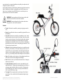
1
Most Voloci dealers are trained to perform maintenance and service tasks. Feel free to contact your dealer for service or technical support. Dealers specially trained to perform service are listed on our website http://www.voloci.com. TM Technical support inquiries may be made by email to [email protected]. You may also reach a technical support person by telephone during normal business hours (Eastern Standard Time) at +1 603-742-1037. NiMH User’s Manual Safety Not For Children – Adults Only This manual contains important safety, performance, and maintenance information. Read this manual before you use your motorbike for the first time. Keep the manual for future reference. Voloci is a trademark of Nova Cruz Products, Inc. The Voloci motorbike is protected by US and International patents pending. Copyright 2002, Nova Cruz Products, Inc., All rights reserved. Warranty Most of your Voloci motorbike is warranted against defects in materials and manufacture for one year from the date of purchase except for the frame and batteries. The frame of your motorbike is warranted for 10 years and the batteries are warranted for 6 months. Nova Cruz will repair or replace at its option your Voloci motorbike if it is defective within the warranty period. You are responsible for the cost of transporting or shipping your motorbike to an authorized dealer or to the Nova Cruz service facility. You must provide proof of purchase to obtain warranty services. This warranty does not cover normal wear and tear, including wear of brake pads, tires, chains, and sprockets. This warranty also does not cover damage due to jumping, crashes, submersion in water, or other abusive treatment. Removal, modification, or tampering with electrical or electronic components of your motorbike without prior authorization from Nova Cruz voids your warranty on those components. This is a consumer warranty and does not apply to vehicles used in commercial or rental applications. Contact The Voloci electric motorbike is designed for adults. It is a highperformance vehicle that can travel at speeds of up to 30 mph (50kph). It is not intended for use by children under age 16. Keep your motorbike away from children. Never leave the keys to your motorbike where they could be found and used by children. WARNING: The Voloci motorbike is a motor vehicle. Travel via any motor vehicle subjects the rider to the risk of accident and injury. Serious injury or death is possible as a result of falls, loss of control or collisions with other vehicles or objects. WARNING: The risk of accident and injury is substantially increased in wet or icy road conditions. Not only is visibility impaired, but the handling, braking, and control of the motorbike is substantially diminished. Use great caution when operating your motorbike on wet roads. NEVER ride your motorbike in snowy or icy conditions. WARNING: Riding at night or in periods of low light is much more dangerous than riding during the daytime. Your visibility and that of other drivers is substantially impaired from dusk to dawn. Use great caution when operating your motorbike in conditions of low light. Always use your head and tail lamps when dark. WARNING: Riding a motorbike without a DOT-approved helmet dramatically increases the risk of head injury and death. Never ride your motorbike without wearing a properly fitted and properly adjusted helmet. WARNING: The Voloci motorbike is designed for a single rider only. Riding with one or more additional passengers is dangerous and may result in personal injury to both the driver and passenger. Service information you may need in the future is available at our website http://www.voloci.com. Copyright 2002, Nova Cruz Products, Inc. All rights reserved. Nova Cruz and Voloci are trademarks of Nova Cruz Products, Inc. Revision of July 10, 2002 SAFETY NOTE: To minimize the impact of unintentional throttle twists when the Voloci is stationary, the on-board microprocessor limits the power delivered to the motor at very low speeds (less than 0.5 mph). Once the Voloci is traveling over 0.5 mph, full power resumes. Ride safely: § Don’t ride when it’s icy. § Use great caution when the roads are wet. § Use great caution when it’s dark out. § Wear your helmet. § Never ride with a passenger. § Ride in control at all times. § Never stunt ride. Unpacking and Assembly If you purchased your Voloci motorbike from a dealer, your dealer has already completed any required unpacking and assembly tasks. If you purchased your motorbike directly from Nova Cruz, you must follow these assembly instructions. If you get stuck or encounter any difficulties, please call us at 1-888-353-4464 in the U.S. or outside the U.S. at 603-742-1037. 1. Note: If you are uncomfortable performing this level of assembly or if you cannot secure the required tools, please contact any bike, moped, or motorcycle shop and ask them for assistance. Collisions Your motorbike is designed to withstand years of normal riding. However, collisions can substantially weaken the structure of the motorbike. If you accidentally have a minor collision with a curb, wall, or other fixed object, inspect the motorbike for loose or bent parts. If you find such parts, contact your dealer or Nova Cruz for repair or replacement. If you collide with a fixed object at speeds in excess of 10 mph (16 kph) and/or are thrown from the motorbike after a collision, you could severely damage the structure of the vehicle. In such cases, please contact your dealer or Nova Cruz for repair or replacement. 2. Remove your motorbike from its shipping carton by lifting it straight up out of the box. Using two people for this makes removal from the box much easier. When practical, retain your shipping carton and packing material in case you need to package or ship your motorbike in the future. IMPORTANT: REMOVE THE BATTERY FROM THE VOLOCI BEFORE PROCEEDING WITH ASSEMBLY. Pull the battery handle toward the seat and lift up to remove. If you would like to make battery charging progress while you assemble your Voloci, plug the battery into the battery charger now. 3. Remove the handlebar assembly from its packaging. Within the secondary box locate the assembly hardware pictured in the photo below. These are identified by the letters in the photo. Registration and Insurance Information The laws regulating electric motorbikes vary widely from state to state and from country to country. In most regions, the Voloci motorbike is classified as a “moped” for regulatory purposes. However, in some areas, electric motorbikes are unregulated, and in other areas they are regulated by very specific laws. You must check the laws in your country, state, and municipality to determine the licensing, registration, and insurance requirements in your area. The following tools are required for assembly. - 5 millimeter Allen wrench - Adjustable wrench - 10 millimeter Open-End wrench - 14 millimeter Closed-End wrench - Standard pliers - Torque wrench (optional) H Certificate of Origin Insurance Insurance against various types of possible incidents is probably not provided by your existing insurance policies. Please check with your insurance company about the details of your coverage and if insurance requirements exist in your state. Copyright 2002, Nova Cruz Products, Inc. All rights reserved. Nova Cruz and Voloci are trademarks of Nova Cruz Products, Inc. E A A “certificate of origin” and/or a bill of sale may be required to register and/or insure your motorbike. These documents are provided as separate items and should be included with the documents provided to you by your dealer (or by Nova Cruz if you purchased directly from the factory). C D B G F Revision of July 10, 2002 4. Install horn (A) using two M6x16 screws (B) inserted through holes from the front and putting an M6 Nylock nut (D) on each screw. Torque to moderate tightness using a 5mm Allen wrench and a 10mm Open-end wrench. The perforations on the horn should be facing forward. The two electrical connections should be facing in toward the bike – if they are not, rotate the circular part of the horn until they do. Step 7: Handlebar orientation Step 4/5: Installation position for horn and directional on front end of Voloci 5. 6. 7. Install the two front directionals (F) (from the bag) using a 10mm Open-end wrench and a 5mm Allen wrench. It does not matter which directional goes on which side – they are symmetrical. Feed the wires for each directional into the larger hole in the headlight bracket and press the post on the directional into the wire hole. Align the hole on the directional with the smaller hole in the headlight bracket and insert the M6x16 bolts (B) from the outside in. Attach the M6 Nylock (D) nuts to each bolt on the inside of the headlight bracket and torque to moderate tightness. Note: be very careful with all of the directionals as they protrude from the bike and are easily subject to damage. Position the handlebar assembly on top of the handlebar mounts with the throttle controls on the right side of the Voloci (looking forward). The throttle handle is the handle that twists and has a red switch on it. Making sure that no wires from the handlebar go below or between the handlebar mounts, assemble the handlebar assembly to the front steering assembly using the two handlebar clamps (E) and four M6x30 screws (C). The handlebar should be centered side-to-side between the clamps and set to the front-to-back angular position that the rider prefers before tightening (see photo below with suggested orientation). The clamp screws should be tightened with a 5mm Allen wrench to 1.0 kg-m (7 ft-lb) of torque. (Very tight.) As you tighten the clamps rotate among the four clamping screws until all are tightened equally and have even gaps between the top and bottom clamps in all 4 places. Copyright 2002, Nova Cruz Products, Inc. All rights reserved. Nova Cruz and Voloci are trademarks of Nova Cruz Products, Inc. Step 8: Headlight tilted forward 8. Loosen the headlight bolt in the side-to-side orientation with a 14mm Closed-end wrench on one side and an adjustable wrench on the other and tilt forward. A 14mm socket is also useful to loosen and tighten the headlight bolt – DO NOT FORCE headlight to rotate forward. 9. Connect the electrical wiring on the front end of the Voloci in the following order. Firmly push each connector set together after aligning. NOTE: If you need to disconnect any connectors, be sure to pull only on the connectors and not the wires. If the wires are pulled they will separate from the connector and cannot be restored without crimping on a new connector. a. Note: Leave all wire ties in place. They are holding the wiring harness in the desired position. b. Plug the 3 pin connector from the throttle on the handlebar assembly into its mate emerging from behind the headlight mount. If you need to disconnect there is small tab to pull up on one half of the connector. c. There is 1 black wire with a rectangular pink connector emerging from behind the headlight mount. Connect this wire to the bottom contact on the horn. d. There are 3 black wires with round red connectors emerging from behind the headlight mount. Connect 1 of these wires to either of the 2 wires emerging from the left directional. Connect 1 of these wires to either of the 2 wires emerging from the right directional. Do not connect the 3rd black wire yet. e. Connect the large 10-pin connector emerging from behind the headlight mount to its mate coming from the handlebar assembly. Push firmly together. If you need to disconnect there is small tab to depress on the smaller half of the unit. f. Connect the white wire emerging from the large connector to the blue wire emerging from the headlight. Revision of July 10, 2002 g. Connect the orange wire emerging from the large connector to the other wire emerging from the LEFT directional (as you are sitting on the bike and facing forward). h. Connect the purple wire emerging from the large connector to the other wire emerging from the RIGHT directional (as you are sitting on the bike and facing forward). i. Connect the black wire emerging from the large connector to the remaining black wire with the red round connector emerging from behind the headlight mount. j. Connect the last wire (either brown or pink) emerging from the large connector to the top contact on the horn. 10. Positioning the large connector either vertically to the right of the headlight mount (while sitting on the bike and looking forward) or horizontally just above and behind the headlight mount (whichever seems to naturally fit better), neatly bundle the loose wires and rotate the headlight up to its forward facing position. CAUTION: BE VERY CAREFUL NOT TO TRAP OR CUT WIRES BEHIND HEADLIGHT AS IT IS ROTATED BACKWARD. The headlight will passively hold the wires in place when it is in the upright position. After ensuring that the headlight is aiming straight forward, tighten headlight bolt with 14mm Closed-end wrench and adjustable wrench to 1kg-m (7ft-lb) or moderately tight. Make sure that the wires are not pinched as the handlebars are turned all the way to the left and right. under the seat. Note: be very careful with all directionals as they protrude from the bike and are easily subject to damage. 12. Start with the left brake (as you are facing forward on the bike) which controls the rear brake assembly. Locate the rear brake cable. It protrudes from the bottom of the bike coming out under the Voloci logo on the chassis. 13. On the inside of the left brake lever on the handlebar, you will find two rotating barrel screws – these are brake adjusters. Turn these clockwise so that they are screwed in as far as possible into the brake levers. Then back each screw out until the slots on both are lined-up with the slot in the brake lever housing (see photo in step 15). Brake Lever Brake Lever Housing Barrel Screws Brake Cable Steps 13 and 14: Rotating barrel screws and brake cable insertion 14. While pulling the left brake lever, slide the metal bulb at the tip of the rear brake cable into the hole in the left brake lever and slide in as far as it will go. IMPORTANT: Make sure that the brake cable goes between the horn and the headlight and travels behind the headlight as it goes to the brake lever. When fully inserted you should see just wire through the hole in the lever. Insert one of the brake lever pins (G) in the hole from the top with the larger opening on the pin away from the brake cable sleeve (black part). If inserted properly the pin should “capture” the wire and seat flush to the top of the brake lever. Step 10: Connector in vertical position (left) and horizontal position (right) 11. Install the two rear directionals (already on the Voloci) using a 10mm Open-end wrench and a 5mm Allen wrench. On each directional remove wire ties and locate 2 M6x16 (A) bolts and 2 M6 Nylock nuts (D). If your Voloci arrived with a rear rack these fasteners may already be installed next to the directional wires. Feed the wire for each directional into the hole in the seat frame and press the post on the directional into the wire hole. Align the other hole on the directional with the hole in the seat frame and insert the bolts from the outside in. Attach the nuts to each bolt on the underside of the seat frame and tighten. Be careful not to damage any of the wiring Copyright 2002, Nova Cruz Products, Inc. All rights reserved. Nova Cruz and Voloci are trademarks of Nova Cruz Products, Inc. Step 15: Three lined up slots (left) and brake wire in first slot before full insertion (right) Revision of July 10, 2002 15. Making sure that the three slots in the brake lever and rotating barrel screws are still lined up, work the wire into the slots and seat the metal end of the cable sleeve into the smaller of the rotating screws. To do this you will have to pull the brake lever to tension the brake cable and provide some slack to work with (getting more wire out of the black cable sleeve). Holding the metal end of the cable sleeve against the larger rotating barrel screw and pulling the brake lever will provide some more cable to work with (see photo). This may take some fiddling but it will work. mirror nuts and washers (they are on the mirror mounts). Torque to moderate tightness. Some riders insert the mirrors from the underside and position them below the handlebars for better visibility. When installing the right mirror (when facing forward on the bike), please make sure not to pinch the throttle wire with the mirror nut on the underside of the controls. Make sure it is clear of the thread and the nut. Step 19: Mirror mounted on right brake housing Step 15: Completed brake cable insertion 16. The brakes have been set at our factory and should be in the right position. Check to see that depressing the brake lever between 1/2 and 2/3 of the way causes the brake to fully engage and that no cable slipping occurs when the lever is depressed. You should be able to pull the brake levers without them touching the handlebar. If the lever can be fully depressed, adjust the two rotating barrel screws on the brake lever housing counter-clockwise to tighten up the cable until the 1/2 to 2/3 point is reached when the brake is fully depressed. When the desired point is reached, turn the barrel screw closest to the brake lever housing (the larger diameter screw) clockwise until it hits the housing. This will lock in the setting. If you cannot get the brakes adjusted properly using the rotating barrel screws, please see the section later in the manual titled “Brake Tensioning.” 17. Repeat steps 12 through 16 for the right brake lever and the brake at the front wheel. For further information about brake settings, please refer to the RST Brakes Owners Manual included in this package. NOTE: The brakes are a key safety feature on the Voloci. If you are unsure about setting the brakes, please contact your dealer, call Nova Cruz, or visit a local bike shop for assistance. 18. Inflate the tires to 73 psi (5 bar). If you do not own a floor pump with a pressure gage, you should consider purchasing one for future use. The valve on your motorbike tubes is a “Schrader” type, like that found on most automobile tires. 19. Install the 2 mirrors (H) by inserting the mirror mount into the top of the hole in the brake lever housings and securing it from the underside with the Copyright 2002, Nova Cruz Products, Inc. All rights reserved. Nova Cruz and Voloci are trademarks of Nova Cruz Products, Inc. 20. Remove the protective tape from the terminals of the NiMH battery pack and insert it from the top of the motorbike into the opening between the two side spars of the frame. The handle end of the battery pack should be towards the top front of the motorbike. To install the battery pack, first insert the lower end (with the electrical contacts) into the frame and then pivot the pack down until the top end (with the handle) snaps into place. 21. Adjust the pre-load on the rear suspension (see section later in the manual). 22. Fully charge the battery before use (see battery charging section below). Basic Operation Braking WARNING: Your RIGHT brake lever controls the FRONT brake and your LEFT brake lever controls the REAR brake. This is the convention for motorcycles, but is the opposite of the convention for bicycles. (US law requires this configuration for motor driven cycles.) Please be sure you are comfortable operating both front and rear brakes. Before riding verify that your front and rear brakes are working properly. You should be able to pull the brake levers without them touching the handlebar. In the Revision of July 10, 2002 event that a brake lever touches the handlebar when pulled, please adjust the cable setting and/or replace the brake pads. In most braking situations you should relax the throttle and apply both front and rear brakes. Although your front brake is substantially more effective than your rear brake, be sure to modulate the front (RIGHT) brake lever such that you are not pitched forward over the front of the motorbike. WARNING: Extreme application of the brakes may result in wheel lock and can result in loss of control of the motorbike. WARNING: Extreme braking with the front brake could result in being pitched over the front of the motorbike. Controls § Throttle. The throttle is controlled by twisting the right grip toward the rider. § Brakes. Front and Rear disc brakes are controlled by right and left levers on the handlebars. § Key switch. The main power switch for your motorbike is a “key” switch located beneath the seat on the side of the seat frame. Turn the key switch clockwise to activate the power. If you leave the switch in the on position, the microprocessor controller for the overall motorbike will eventually disable the power automatically. In this event, turn the key off and then on again. Make sure to remove your key when parking your motorbike. This is for both safety and security reasons. § Kill switch. On the right-hand control cluster there is a switch that can be slid sideways. This switch is a “kill” switch. Moving the switch to the “X” position will cut power to the motorbike. You should apply the kill switch whenever you are not riding the motorbike, but when you have left the key in place (e.g., when talking to friends while standing next to the motorbike). § Lights. The headlamp switch is at the top of the right-hand control cluster. This switch activates the front headlight and the taillight. § Horn. The horn is on the top of the left-hand control cluster. Pushing the button activates the horn. § Economy/Performance switch. This switch is in the middle of the lefthand control cluster. Moving switch up (running figure) puts Voloci in a performance mode that delivers full power to the rider. Moving switch down (walking figure) puts Voloci in an economy mode that limits the rider’s top speed and increases range. § Turn signals. The turn signal switch is on the bottom of the left-hand control cluster. Move switch left for left directional and right for right directional. Copyright 2002, Nova Cruz Products, Inc. All rights reserved. Nova Cruz and Voloci are trademarks of Nova Cruz Products, Inc. Revision of July 10, 2002 Horn Light Switch Performance Economy Switch Pre-Ride Checklist Before riding your motorbike, check these items: 1. You are wearing a properly fitting, DOT-approved helmet and the chin strap is secure. 2. The tires are inflated to 73 psi (5 bar). Riding with under inflated tires will result in diminished range. 3. The wheels are securely attached to the motorbike fork and frame, with the front “quick-release” lever securely in the closed position. 4. There are no loose, damaged, or broken components of the motorbike, including lamps, handlebars, mirrors, guards, foot pegs, or frame components. 5. Both front and rear brakes are working properly, with neither brake lever touching the handlebar when pulled back. 6. The battery is fully charged and securely latched in place. 7. The rear-view mirrors are adjusted correctly. 8. The key is in and switched to the ON position and the kill switch is in the RUN position. (We recommend keeping one of the keys in a safe place in case the other is lost. These keys cannot be copied or replaced by Nova Cruz) Directionals Kill Switch Battery Monitor Your motorbike is equipped with a state-of-charge indicator made up of five LEDs just below the handlebars. The number of LEDs illuminated is approximately proportional to the remaining energy in the batteries. 5 LED’s = Full charge 4 LED’s = 80% battery life remaining 3 LED’s = 60% battery life remaining 2 LED’s = 40% battery life remaining 1 LED = 20% of battery life remaining (this last LED is red) Note: When just the one red LED is illuminated you should have 2-3 miles (3-5 km) of range left and should recharge your batteries as soon as possible. When the red LED begins to blink you have approximately 1 mile left before the Voloci shuts down. The battery monitor is microprocessor controlled and employs a state-of-charge algorithm that uses information about how much energy has been consumed from the battery pack to infer how much energy remains. However, this algorithm can be “fooled” into an inaccurate reading if you remove your battery pack and then replace it without fully recharging the battery. For maximum accuracy, you should either (1) fully charge your battery after it has been replaced on the motorbike or (2) fully charge the battery before replacing it in the motorbike. The battery indicator can also be fooled by hilly terrain that can temporarily drop the measured voltage of NiMH batteries. The Voloci motorbike is equipped with battery protection circuitry that will disable the motorbike when the batteries are depleted so far that further use could compromise the longevity of your battery pack. When you have reached this point, you must either swap battery packs or recharge. WARNING: If you try to over-ride the battery protection circuitry, you risk damaging your NiMH battery. Copyright 2002, Nova Cruz Products, Inc. All rights reserved. Nova Cruz and Voloci are trademarks of Nova Cruz Products, Inc. Range Your Voloci motorbike is one of the most efficient vehicles ever built. It can travel as far as 25 miles (40km) on about 5 cents worth of electricity. Nevertheless, your actual range depends on: § § § § § § § Rider weight (the heavier the rider, the less the range) Terrain (the more hills, the less the range) Speed (the faster, the less range) Rider size (the larger the “frontal area”, the greater the wind drag) Acceleration (the harder the acceleration, the less the range) Tire pressure (must inflate tires to 73psi, or 5 bar, for optimal range) State of charge (batteries must be fully charged for maximum range) The maximum range a rider can achieve on one battery charge under essentially perfect conditions is about 25 miles (40km). These conditions are: a smooth, flat road surface, rider weight less than 165lbs (75kg), a speed of less than 20 mph (36kph), and no headwind. A 220 lb rider (100kg) riding up and down hills at 25mph (42kph) might get only 12 miles (20km) of range on a single battery charge. Therefore, you should experiment with your riding style and typical trip conditions to determine what range you can expect. Revision of July 10, 2002 Your motorbike is equipped with a state-of-charge indicator made up of five LEDs mounted just below your handlebars on the motorbike frame. The number of LEDs illuminated is approximately proportional to the remaining energy in the batteries (see battery monitor section for details). When only the one red LED is illuminated you should have 2-3 miles (3-5 km) of range left and should recharge your batteries as soon as possible. Note that you can restore a few miles/kilometers worth of energy in 15-30 minutes of charge time, should you actually fully deplete your batteries while away from your normal charging station. (Of course, you need to bring your charger with you to take advantage of this rapid recharging feature.) The figure below illustrates how speed and rider weight influence range. Note that your range will be greatest at low speeds, while your range is lowest at the top speed of the motorbike. Also note that this range is for the single battery pack. Double the range if you are carrying a double battery pack. Voloci Range Your motorbike is equipped with a switch that allows you to select “economy” or “performance” mode. The essential difference between these modes is the amount of electrical current that the controller will allow to be delivered to the motor. In economy mode, the current is limited to about 60 percent of the system capability. This will diminish the acceleration, hill climbing, and top speed of the motorbike, but will also limit the rate at which energy is drawn from the batteries. Using the motorbike in performance mode does not automatically mean you will achieve less range. A disciplined rider with a good feel for the machine can limit the power demanded from the batteries when climbing hills, accelerating from a stop, or when cruising at top speed. However, when in performance mode, these limits are not applied automatically. The switch for economy and performance mode is located on the left-hand side of the handlebar and is labeled as shown below. Batteries and Charging 35 Your motorbike contains a removable Nickel Metal Hydride (NiMH) battery pack. 60 kg 132 lb 30 Range (miles) Economy/Performance Mode WARNING: the batteries on your motorbike contain a tremendous amount of energy when charged. Shorting the contacts of the batteries can result in sparks and the flow of high current. Use caution when transporting and storing the batteries to avoid touching the electrical contacts with metal, liquids, or other conductive materials. 75 kg 165 lb 90 kg 198 lb 25 Charging Charging a single NiMH battery pack takes about 3 hours. Your battery charger is a “smart charger” and performs a pre-programmed cycle on each charge. You will not damage your batteries by leaving them plugged into the charger for a day or two. However, if you expect to leave your motorbike idle for more than a day, you should disconnect the charger. 20 15 10 5 10 15 20 25 30 Speed (mph) Again, the factors that most influence motorbike range are the weight of the rider (heavier riders require more energy to move a given distance than lighter riders), the speed at which you ride (the faster you ride, the more energy you use for a given distance traveled), and the terrain over which you ride (traveling over hilly terrain requires much more energy than traveling over flat terrain). Copyright 2002, Nova Cruz Products, Inc. All rights reserved. Nova Cruz and Voloci are trademarks of Nova Cruz Products, Inc. NiMH battery packs are immune to any so-called memory effect. You should recharge your batteries at every convenient opportunity and not wait until the batteries are fully depleted before recharging. In fact, you will get the maximum life from your batteries if you recharge them after every use. All batteries including NiMH get warm when rapidly discharged. When the NiMH batteries are warm, they may not charge immediately. This is because your smart charger senses battery temperature and does not charge the batteries until they have cooled down. If you ride your Voloci hard for more than 5 to 10 miles there is a chance that you will have to wait until the battery cools down before it can be charged. NiMH battery chargers monitor battery temperature to measure level of charge so the charger will not charge the battery if it is warm. If this occurs just plug the charger in and the charger will flash yellow while it waits for the battery to cool Revision of July 10, 2002 down. The charger will show solid yellow when a chargeable temperature is reached and will begin charging. Your NiMH battery charger may be operated at either 110 Volts or 220 Volts, depending on the electricity standard in your country. However, you MUST select the correct voltage using the switch on the end of the charger. Temperature and Storage All batteries deliver less performance at very low ambient temperatures. When you use your motorbike in cold winter weather, you will get the best performance if you store your motorbike indoors. Once underway, the internal heating of the batteries allows them to perform very well even in cold weather. If NiMH batteries are stored in the cold (less than 40 degrees F), the performance of the Voloci will be noticeably reduced. Battery Monitor and Protection Circuitry The battery monitor for the NiMH pack is microprocessor controlled and employs a state-of-charge algorithm that uses information about how much energy has been consumed from the battery pack to infer how much energy remains. However, this algorithm can be “fooled” into an inaccurate reading if you remove your battery pack and then replace it without fully recharging the battery. For maximum accuracy, you should either (1) fully charge your battery after it has been replaced on the motorbike or (2) fully charge the battery before replacing it in the motorbike. The battery indicator can also be fooled by hilly terrain that can temporarily drop the measured voltage of NiMH batteries. The Voloci motorbike is equipped with battery protection circuitry that will disable the motorbike when the batteries are depleted so far that further use could compromise the longevity of your battery pack. When you have reached this point, you must either swap battery packs or recharge. WARNING: if you try to over-ride the battery protection circuitry, you risk damaging your NiMH battery. Break-In Period New NiMH battery capacity increases significantly over the first few charge/discharge cycles. You will not reach the maximum speed and range of your new Voloci until about your tenth full charge/discharge cycle. Performance of the battery indicator will also improve during this break-in period. Charge Connectors: On the Voloci chassis (left) and on the NiMH battery (right) Security We strongly suggest that you lock your Voloci whenever you are not riding it. See the accessory page on www.voloci.com for tips on recommended lock-sets. Please note that all locks are only deterrents and are not fool-proof. Do not leave your Voloci in unsafe locations. If possible, store your Voloci indoors and, if you must leave it outside, try to take the battery inside with you. Maintenance Your Voloci motorbike should require less maintenance than a gas-powered vehicle. However, the following areas of maintenance may require your attention periodically: WARNING: Always ensure that power is switched off before working on any part of the drive train. This includes sprockets, chains, disc brakes, and wheels. Serious injury may result. § Charge Connectors The Voloci NiMH batteries are chargeable in two ways: 1) through a charge connector located on the motor cover on the left side of the motorbike or 2) through a charge connector directly on the battery case. The charge connector on the battery is designed to be used when the battery is removed from the Voloci. Note that all charger connectors are “keyed” and must be attached in the correct orientation. If oriented properly, the charger connectors should connect easily. DO NOT FORCE the charge connectors into place. Copyright 2002, Nova Cruz Products, Inc. All rights reserved. Nova Cruz and Voloci are trademarks of Nova Cruz Products, Inc. Chain tension. Your chain will gradually wear with increasing use. As a result of this wear, the length of the chain may grow slightly. You should take up the slack in the chain periodically in order to ensure that the chain is not loose. When you can no longer take up the slack in your chain, the chain is worn out and should be replaced. To adjust the chain tension: 1. Loosen the axle nuts on each side of the rear axle. This will require two 17mm wrenches (or adjustable wrenches). Revision of July 10, 2002 2. Loosen the socket head clamp screws that clamp the rear adjustment cams (through which the axle passes). This will require a 5mm Allen wrench. 3. Using a large screwdriver inserted into the slots in the adjustment cams, rotate the cams in order to displace the rear axle rearward and thereby tighten the chain. NOTE: The shaft should always be biased towards the top on the adjustment cams. When the chain is properly tightened, you should just be able to make it touch the rear swing arm when you push it up toward the reference bolt indicated in the photo. WARNING: Do not over tighten the chain as it will cause poor performance and ruin the bearings. During this step make sure that the rear wheel is balanced sideto-side and remains centered between the rear swing arms. Since it is tough to see, you can use your fingers to gauge how the wheel is centered between the left and right swing arms. 4. Re-tighten the socket head screws that clamp the adjustment cams. Torque setting: 1.0 Kilogram-meters (7.5 Foot-pounds) 5. Re-tighten the rear axle nuts. Torque setting 0.8 Kilogram-meters (5.5 Footpounds) § Chain lubrication. Your chain will need periodic lubrication. Any motorcycle type (wax or oil based) lubricant can be used. Chain Tensioning: Identifiers (above) and tension reference (below) Follow the recommended application method for the product. A good indication when the chain needs lubricating is when the rollers on the chain are becoming dry and/or shiny. Reference Bolt In dusty conditions the chain will need more frequent lubrication and cleaning. Copyright 2002, Nova Cruz Products, Inc. All rights reserved. Nova Cruz and Voloci are trademarks of Nova Cruz Products, Inc. § Tire replacement. Your tires should last several thousand miles. When the tread depth is less than 1/16 inch (1.5mm) you should replace your tires. The tires for your Voloci motorbike are custom made for this product and contain tubes. You must obtain approved replacement tires from Nova Cruz or your dealer. The process of replacing a tire is very similar to that for replacing a bicycle tire. If you are not thoroughly familiar with this process, you should contact your dealer or Nova Cruz for assistance. § Headset adjustment. Your headset may need adjustment when new. (Settling). Loosen the three screws clamping the stanchions and steer tube in the top triple clamp. Loosen the tensions in the adjuster, center the spacer ring over the steer tube and re-tension the adjuster while applying pressure to the top triple clamp, by pushing down on it with the front wheel on the ground. The adjuster should draw the clamp and head tube together, which will seat the bearings. Revision of July 10, 2002 Tighten up the clamp screws, head tube screw first. Test the adjustment by sitting on the bike and rock it back and forth while holding the front brake. If there is any movement in the bearing, it will require adjustment again. 2) At the brake assembly at the wheel, one person should push the silver lever all the way forward with one hand (engaging the brake). With the other hand this person should pull the brake cable further through the cable clamping mechanism by pulling the cable with pliers grabbing the end of the cable. Be careful not to deform the spring and boot by keeping them in a straight line as the lever is compressed. Headset Adjustment: Top clamp adjustment points (left) and tension adjuster and spacer ring (right) § Brake tensioning. The lever action of your brakes will change as the brake pads wear with use. The barrel adjuster on the lever perch should be screwed out to take up the slack and locked with backing nut. This procedure is described in detail in the assembly section. Brake Tensioning Step 2: Brake cable pulling Larger adjustments can be accomplished at the brake caliper end of the cable. To perform the adjustment at the brake caliper end (at the wheel) please follow these steps and the accompanying photos. Also, you can see the RST brake instruction booklet included in your package. 3) While one person holds the lever and pulls the cable, the other should tighten the cable clamping mechanism by using a 2.5mm and 3mm Allen key on each side. These screws should be set VERY tightly possible by hand to avoid cable slipping. When the clamping mechanism is tight, the lever and cable can be released. 1) To perform this adjustment, you will need two people – find a friend to help. Use a 2.5mm and a 3mm Allen wrench to loosen the cable clamping mechanism. When loose, the cable should slide freely within the clamping mechanism. 4) If necessary, fine tune the depressed position of the brake lever on the handlebar by using the rotating barrel screws. This procedure is described in the assembly section. § Brake balancing. If you hear a rubbing noise from the brakes when they are not depressed and the tires are rotating, your brake pads may be out of balance. In other words, the disc may be closer to one pad than the other. To fix this on either the front or rear brake, loosen the two screws shown in the photo using a 4mm Allen wrench. Fully depress the brake lever and hold it there. While the lever is depressed, firmly tighten both screws. Release the brake lever. Brake Tensioning Step 1: Brake cable clamping mechanism Copyright 2002, Nova Cruz Products, Inc. All rights reserved. Nova Cruz and Voloci are trademarks of Nova Cruz Products, Inc. Revision of July 10, 2002 Troubleshooting We have included a table below that includes many of the common symptoms that you might experience with your Voloci . If you have problems with your Voloci that cannot be solved via the table or with the instructions above please use the following sequence to solve your problem: § Visit the troubleshooting section of the Voloci service page on the Voloci website at http://www.voloci.com. This section is updated regularly by Nova Cruz and may contain troubleshooting information not included in your user’s manual. § Contact your local Voloci Dealer. § Contact Nova Cruz by e-mail at [email protected] or at 603 742 1037. Brake Balancing: Set screws to loosen for balancing § Adjusting pre-load on rear suspension. To get the best ride, the pre-load on the rear suspension should be set for the weight of the rider. To do this, position the threaded spring adjuster so that when the rider sits on the bike the rear suspension drops by approximately 1 inch at the rear of the seat. Looking from the rear of the bike, rotate the adjuster clockwise to increase pre-load and reduce the suspension drop. Symptom Motorbike does not move when throttle is twisted. Likely Cause § § § § Spring adjuster Spring § Brake pad replacement. The brake pads on your motorbike should last several thousand miles. However, they will require replacement when they are worn out. Consult with Nova Cruz technical support or your dealer for instructions on replacing your brake pads. Instructions are in the RST instruction booklet. § Cleaning your Voloci. Do not use any solvents or polishing compounds to clean your Voloci. Graphics may be damaged. Warm water and soap/detergent should be used for cleaning. Copyright 2002, Nova Cruz Products, Inc. All rights reserved. Nova Cruz and Voloci are trademarks of Nova Cruz Products, Inc. Lights on console do not come on or accessories do not work Reduced braking effectiveness. Key switch is off. Kill switch is in the off position. Battery is depleted. Battery is not fully latched in place (NiMH only). What to do § Turn key switch on. § Slide kill switch to on position. § Charge battery. § Remove and reinsert battery and ensure it is latched in place. § Loose wiring § Check wiring connections under seat and near headlight § Worn out brake pad. Brake cable too loose. § Uneven rubbing noise. Pads unbalanced § Replace brake pads. Turn “barrel adjuster” on brake lever to tighten cable. Re-tension brakes. Balance brakes § § § Revision of July 10, 2002 Diminished range Low tire pressure. Hilly terrain, heavy rider, and/or high speeds. Battery still in break-in period. § Inflate tire. § Battery not fully charged. Battery near end of its useful life (700 cycles). § Modify riding habits or use second battery pack. Continue charging and discharging Charge battery fully. Replace battery pack. § Battery too hot to charge. § § Blown battery fuse. § § Loose headset bearing § § Lower tire pressure or flat. Chain too loose or too tight § Worn chain/sprockets Pre-load too tight causing rubbing on chain guard § § § § § § Yellow charger lamp blinking (NiMH charger only) Vague or wobbly steering Noisy drive train § § § Copyright 2002, Nova Cruz Products, Inc. All rights reserved. Nova Cruz and Voloci are trademarks of Nova Cruz Products, Inc. § § § § Wait until battery cools. You can leave the charger on and it will start automatically. Contact your dealer or Nova Cruz for replacement. Tighten headset by resetting tension adjuster. Check pressure or replace tire/tube Make necessary chain adjustments and lubricate Replace chain/sprockets Adjust pre-load Revision of July 10, 2002