1
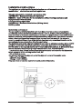
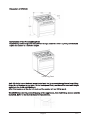
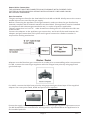
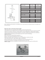
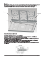
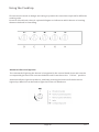
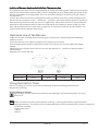
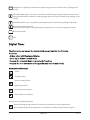
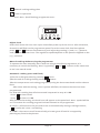
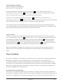
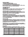
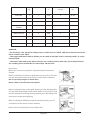
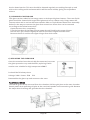
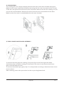
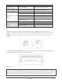
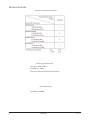
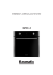
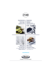
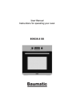
Page 1 V 2.0 CONTENTS Important Notes -------------------------------------------------------Page 3 Installation Instructions -----------------------------------------------Page 5 Oven Accessories -----------------------------------------------------Page 11 Control Panel ----------------------------------------------------------Page 12 Using the Cooktop -----------------------------------------------------Page 13 Using the Electric Oven ------------------------------------------------Page 14 Digital Timer -----------------------------------------------------------Page 16 Oven Cooking & Cooking Time ----------------------------------------Page 18 Cleaning and Maintenance -------------------------------------------Page 21 Troubleshooting -------------------------------------------------------Page 24 Technical Data ---------------------------------------------------------Page 26 Warranty and Ser vice -------------------------------------------------Page 27 V 2.0 Important Notes Please keep this handbook for future reference. ●This appliance is designed to be handy for any adult to use at home. Children should be super vised to ensure that they do not play with the appliance. ●Accessible parts may become hot during use. To avoid burns young children should be kept away. ●This product must be connected in accordance with current gas and electrical regulations. A fixed wiring installation is to be done only by an authorized electrician. ●Authorised personnel must perform subsequent adjustments or repairs that may be necessar y with care and full attention. ●For any repairs, always contact authorized Customer Ser vice Centre and ask for original spare parts. Repairs by untrained people may lead to damage and void the warranty. ●The appliance must only be used for what it has been made for, that is, cooking for home use. Any other use is considered improper and, as such, dangerous. ●The manufacturer cannot be held responsible for any harm to people or damage to things deriving from an incorrect installation or maintenance or from an erroneous use of the appliance. ●Once the outer wrapping and the inner wrappings of the various parts have been removed, check and make sure that the appliance is in perfect condition. If you have any doubts, do not use the appliance and contact authorised personnel. ●The packaging materials used (cardboard, bags, polystyrene foam, nails, etc.) must not be left anywhere which could be easily reached by children. To safeguard the environment, all packaging materials used are environmental friendly and recyclable. ●The electrical safety of this appliance is only guaranteed if it is correctly connected to a good earth system, as prescribed by the electrical safety standards. The manufacturer declines all responsibility if these instructions are not followed. Should you have any doubts please contact authorised personnel. ●Prior to connecting the appliance, please ensure that the rating plate data corresponds to the gas and electricity mains rating as described in “ TECHNICAL DATA”. ●If you are using a socket near the appliance, make sure that the cables of electrical appliances that you are using do not touch the hobs and are far enough from all hot parts of the hobs. ●Do Not spray aerosols in the vicinity of this appliance while it is in operation. ●Do Not store or use flammable liquids or items in the vicinity of this appliance. ●NOT FOR USE IN MARINE CRAFT, CARAVANS OR MOBILE HOMES. ●DO NOT MODIFY THIS APPLIANCE. ●The use of gas cooking appliance produce heat, moisture and products of combustion in the room which it is installed. For this reason the room must be well ventilated, keeping the natural ventilation openings free and switch on the mechanical ventilation system (suction hood or electric fan). If the hob is used for a long time, additional aeration may be necessar y, for instance, opening up a window, or a more effective ventilation by increasing the power of the mechanical system if there is one. ●WARNING – In order to prevent accidental tipping of the appliance, for example, kids climbing onto the opened oven door, the stabilising means must be installed. Please refer to installation instructions. Page 3 V 2.0 ●Do not use the oven door as a shelf. ●Do not push down the opened oven door. ●Ensure that the appliance is switched off before replacing the lamp to avoid the possibility of electrical shock . ●Do not use harsh abrasive cleaners or sharp metal scrapers to clean the oven door glass since they can scratch the surface, which may result in shattering of the glass. ●Steam cleaner is not to be used. ●Fixed wiring must be protected. ●Means for disconnection must be incorporated in the fixed wiring in accordance with the wiring rules. ●During use the appliance becomes hot. Care should be taken to avoid touching heating elements inside the oven. ●The appliance must be switched off before removing the guard and that, after cleaning, the guard must be replaced in accordance to instructions. ●This product must not be disposed with the domestic waste. It has to be disposed at an authorised bin for recycling the appliances. ●This appliance is not intended for use by person (including children) with reduced physical, sensor y or mental capabilities or lack of experience and knowledge. Unless, they have been given super vision or instruction regarding the use of appliance by personnel who is responsible for their safety. ●Always make sure all the controls are off or closed when the appliance is not in use. ●When the burners are in use, do not leave them unattended. Make sure there is no kids in the area. Check that pan handles are positioned correctly and always keep an eye on the pan whenever oils or fats are used as they are inflammable. ●Never tr y to extinguish fires with water, but switch the appliance off immediately then cover the flame with a lid or fire blanket etc. ●If the supply cord is damaged, it must be replaced by the manufacturer, its ser vice agent or similar qualified persons in order to avoid a hazard. ●If the range is placed on a base, measures have to be taken to prevent the appliance slipping from the base. Refer to anti-tilt chain instructions.Do not use the oven door as a shelf. Page 4 V 2.0 Installation Instructions The appliance must be installed by authorised personnel in accordance to the manufacturer ’s instructions and local regulations. This appliance must be installed in accordance with: AS/NZS 5601 - Gas Installations (for Australia) NZS 5261 – Code of Practice for the Installation of Gas Burning Appliances and Equipment (for New Zealand) Local gas fitting regulations AS/NZS 3000 – Electrical Installations (Wiring Rules) Building codes Installation environment The gas appliance shall be installed such that the surface temperature of any nearby combustible surface will not exceed 65°C above ambient. If there is insufficient space or natural air flow to meet this requirement, creating an air gap between a heat shield and/or insulating material and the combustible substrate may be effective. Care should be taken where a combustible surface is covered by a non-combustible material. For example, covering a combustible surface with stainless steel may not prevent heat transfer and in some circumstances a hazardous situation could arise. The materials used in the adjacent cabinets is to be able to withstand a temperature of 90°C or higher. Combustible materials, such as curtains, must be at the minimum distance of 500mm. Refer to the diagram below, any vertical combustible surface, A, which is less than 200mm measured from the peripher y of the nearest burner, must have either i.B of not less than 150mm above the peripher y of the nearest burner for full dimension (width or depth) of the cooking surface area, OR ii.C of 10mm or more. The distance between the highest part of the highest burner of the cooker and a i.Exhaust fan is 750mm ii.Range hood is 600mm Diagram below shows the requirements and product dimension. Page 5 V 2.0 Dimension of OFS9020 Installation of the Freestanding Unit Remove all protective plastic film (if there is any). Install the levelling feet provided and adjust the cooker to a suitable height. Levelling Feet Anti-tilt chain is provided and meant to be installed to prevent the appliance from tilting for ward and damage to gas pipe. Fix the hook panel firmly on the wall at a suitable height and place the chain over the hook . After that, make sure the chain is taut and the cooker will not tilt for ward. WARNING: In order to prevent tipping of the appliance, this stabilizing means must be installed. Refer to the instructions for installation. Page 6 V 2.0 Power & Gas Connection: THE APPLIANCE MUST BE CONNECTED IN ACCORDANCE WITH CURRENT GAS & ELECTRICAL RULES AND REGULATIONS. INSTALLATION IS TO BE DONE ONLY BY AUTHORISED PERSONNEL. Gas Connection The gas settings are listed in the data label for both NG and ULPG. Kindly ensure the correct nozzle injectors are used for the gas supply. Before connecting the appliance to the gas network , make sure that the gas distribution network complies with the details stated in the data label. This appliance must be installed in compliance with relevant gas standards and / or codes of practice applicable. The gas connection is via a G ½” male thread loose fitting which is located at the left rear of the cooker. Connect the adaptor to the appliance gas connection, and check if the seals between the adaptor and gas connection are in place and in good connection. Gasket or washer is required for sealing mechanism. Adaptor must be fitted on gas connection to cooker prior to assembling other components. For NG, connect the natural gas regulator with the integral test point by using approved gas thread tape. For ULPG, connect the ULPG test point by using approved gas thread tape. If the supplied adaptor has a test point fitted, ULPG test point is not required. Adaptor with test point fitted OR Ensure the supply connection point, test point and natural gas regulator adjustment screw (for NG installation) are accessible for testing and/or adjustment when the appliance is in the installed position. Page 7 V 2.0 There are two ways to carr y out the connection to the main gas line: A. The freestanding cooker can be connected with rigid pipe as specified in AS/NZS 5601 . B. The cooker can be connected with a Flexible Hose, which complies with AS/NZS 1869 (AGA Approved), 10mm ID, class B or D, not more than 1.2m long and in accordance with AS/NZS 5601. Ensure that the hose does not contact the hot surfaces of the hob, oven, dishwasher or other appliances that may be installed underneath or next to the cooker. WARNING: Ensure that the hose assembly is not in contact with the flue or flue outlet of the oven. The hose should not be subjected to abrasion, kinking or permanent deformation and should be able to be inspected along its entire length. Unions compatible with the hose fittings must be used and connections must be tested for gas leaks. The supply connection point shall be accessible after the appliance is installed. The fixed consumer-piping outlet should be at approximately 150mm to the side of the cooker. The hose should be clear of the floor when the cooker is installed. CAUTION !! Carr y out the connection without applying any kind of stress to the appliance. Warning: The restraint chain supplied should be anchored to the wall so that the chain prevents strain on the hose connections when the cooker is pulled for ward. After gas connection, check for leaks using soapy solution, never a naked flame. Setting of the gas pressure Fit a manometer with a 6mm rubber hose to the test point on the NG regulator. Or fit the manometer to LPG test point if ULPG connection is used. Ignite the wok and auxiliar y burner on and adjust test point pressure to 2.75kPa for ULPG and 1.00kPa for NG. Turn the two burners off and on again and recheck the pressure if it is the same as previously set. Adjust again if required. Test if the cooktop operates correctly After installation and test point setting, each burner ignition and operation must be tested individually and with all burners operating. This testing must be done by the installer before leaving. Supplied Gas Conversion Contact the manufacturer or authorised dealer for conversion. For ser vice, please refer to contact details in the warranty card. Important:. Before carr ying out the conversion, unplug the appliance from the gas and power mains. Replacing nozzles : -Unplug the appliance from the mains to avoid possible electrical shock . -Remove the trivets from the hob -Remove the burner caps -Use a 7mm tubular hex wrench to loosen the nozzles and replace them with suitable nozzles as indicated in the diagram below. -Remove or install regulator for NG or test point adaptor for ULPG. Page 8 V 2.0 Natural Gas Universal LPG (1.0kPa) (2.75kPa) Gas Consumption (MJ/h) 4.00 4.00 Injector Size (mm) 0.91 0.56 Gas Consumption (MJ/h) 6.70 6.70 Injector Size (mm) 1.18 0.71 Gas Consumption (MJ/h) 11.50 11.50 Injector Size (mm) 1.59 0.91 Gas Consumption (MJ/h) 12.50 13.00 Injector Size (mm) 1.62 0.98 Burner : Small Burner : Medium Burner : Large Burner : Wok After replacing the nozzles, the installer must check and set the gas pressure and adjust the burners flame. Adjust the burner minimum flame height This adjustment can only be performed by an authorised personnel. The minimum burner flame is factor y adjusted for the gas type stated on the gas type label adjacent to the gas connection and should not require adjustment. Adjustment may be required if the nozzles have been replaced or there are special mains pressure conditions. The operations necessar y to perform this operation are the following : ●Light the burner ●Turn the knob to the minimum position ●Take out the knob (and gasket if there is any) ●Using a suitable sized screwdriver, turn the regulation screw by the side of the tab shaft until a small regular flame is obtained ●Put the knob back on and turn it quickly from the maximum position to the minimum position, checking that the flame does not go off. ●Make sure the flame is regulated to sufficiently maintain heating of the safety valve thermocouple. Page 9 V 2.0 Warning! Make sure the trivets are placed at the correct position. Take note of the 4mm high bumps at the stainless steel panel, and match it with corresponding concavity of trivets. Trivets reposition between different burners are not allowed. Below shows an example : Concavity Concavity Bumps Electrical Connection WARNING: THIS APPLIANCE MUST BE EARTHED For a direct connection to the electric network is necessar y to mount a circuit breaker before the appliance according to the electrical regulation. Before making connection to the electrical network , check that the domestic system and the limiter valve can take the appliance load. The supply cord must be positioned at such point where the temperature of the point is NOT possible to reach 50K or higher than the ambient temperature. Means for disconnection must be incorporated in the fixed wiring in accordance with the wiring rules. Page 10 V 2.0 If this product is to be connected to a new or upgraded electrical installation, then it must be connected to the supply by a supply cord fitted with: − an appropriately rated plug that is compatible with the socket-outlet fitted to the final subcircuit in the fixed wiring that supplies this cooking range; or − an appropriately rated installation male connector that is compatible with the installation female connector fitted to the final sub-circuit in the fixed wiring that supplies this cooking range. Before connecting to the mains, make sure that: The supply system is regularly earthed, according to the regulations in force. The isolation switch can easily be reached after the appliance is installed. After connection to the mains, check that the supply cable does not overheat. Never use reductions, shunts, adaptors that can cause overheating or burning. The manufacture shall not liable for any direct or indirect damage caused by faulty installation. The installer must ensure that the product installation and connection complies with the local and general gas and electrical regulation in force. Before using the electric oven, we suggest to: Remove the special film covering the oven door glass (if there is any) Heat the empty oven at max. temperature for 45 minutes. This is to remove any unpleasant smell caused by working residues. Carefully clean the internal cavity of the oven with soapy water and rinse it. IMPORTANT! When the oven is in operation, hot surfaces might occur at the oven door. Take note of the “Warning! Hot Surface” sign. Make sure children do not go near the oven when it is in use. Oven Accessories Model : OFS9020 1x baking tray 1x baking tray holder 1x grill insert 1x baking tray handle 2x full rack 1x user manual 1x warranty card Page 11 V 2.0 Control Panel Oven Model : OFS9020 Knob A B C D E F G H Description Digital Timer Function Rotar y Switch Temperature Switch Auxiliar y Burner Large Burner Wok Burner Medium Burner Medium Burner A is a digital timer and it is used to control the power on/off. Other than that, oven cooking time adjustment and program setting can be done here too. The inner cavity light is on when the appliance is in normal working state. OFS9020 uses digital timer to control cooking time and program setting. Refer to Section Digital Timer for the operating instruction. B is function control knob that allows different heating functions to suit different cooking needs. This is for the user to choose the best cooking function for different kind of food. C is used to control the oven temperature and it can be adjusted from 50°C to 250°C. When the inner cavity of the appliance reaches the preset temperature, heating element will be off automatically. It will be on automatically again when the cavity temperature is lower than the preset temperature. D, E, F, G, H are gas hob control knobs. Page 12 V 2.0 Using the Cooktop The burners are made to design and rating to provide the exact heat required for different cooking style. For each control knob, there is a printed diagram to indicate to which burner or heating element the knob is controlling. Automatic Electrical Ignition The command of igniting the burner is integrated in the control knob. Press and turn the corresponding burner knob counterclockwise until it reaches to the “Full on” position. Automatically the ignition sparks on, and keep pressing the knob until the burners is lighted up. Matches can be used to light the burners in blackouts. Page 13 V 2.0 Ignition of Burners Equipped with Safety Thermocouples The appliance burners are to be equipped with safety thermocouples. This thermocouple is part of the flame failure device (FFD). A FFD is designed to stop flammable gas going to the burner if the flame is extinguished. This is to prevent a dangerous build up of gas around the appliance. In the case of burners which equipped with FFD, press and turn the corresponding burner knob counter clockwise to the “maximum“ position. Automatically the ignition sparks on, keep pressing the knob until the burner is lighted up. After the burner is lit, keep the knob pressed for about 10 seconds to allow the safety thermocouples to warm up. By any case after 10 seconds and the burner fails to light up, it means the safety thermocouple is not heated sufficiently. Repeat the process. Optimum Use of the Burners To get the maximum yield with minimum gas consumption, please keep the following points in mind: •Once the burner is lit, adjust the flame according to your needs. •Use an appropriate pan and with flat bottom for each burner (see the table and figure below). •When the pan content starts to boil, turn the knob down to “Reduced rated position” (small flame). •Always put a lid on the pan. Burners Ø pans in cm Wok Rapid Semi-Rapid Auxiliary 22-24 20-22 16-18 10-14 Using the Electric Oven Various cooking functions can be set by selecting different heating elements and temperature setting. Oven Cooking Functions Defrosting- the fan switches on without any heating. Food defrosting time is cut by about 1/3. Static convection mode (conventional cooking) - heat supplied from top and bottom heating elements. The oven must be preheated before food is placed inside. Static convection is ideal for cooking: -Pastr y (dr y-thin) -Pizzas -Bread Page 14 V 2.0 Characteristics of static cooking: -Heat supplied from above and below -Cooking possible on one shelf only -Low moisture removal Bottom Heating Element + Top Heating Element + Fan This function gives even cooking by using both top and bottom outer heating elements with fan to help to circulate the heat evenly. By using the top heating elements, it gives the food a golden brown finish. By putting the food to a lower shelf will make food pastr y bases crispier. To make the food brown and crusty, you can put your food on level 1(the first shelf above the enameled floor) and / or 4 (top level). Top Outer Heating Element + Fan Top Outer Heating Element Maxigrill with Bottom Heating Element This function gives more radian heat directly by using both inner and outer top heating elements and bottom heating element, By using the top heating elements, it gives the food a golden brown finish. By putting the food to a lower shelf will make food pastr y bases crispier. This function is perfect for food in small quantity on shelf level 2 and / or 3. To make the food brown and crusty, you can put your food on level 1(the first shelf above the enameled floor) and / or 4 (top level). Fan Forced- the circular heating element and the fan come into operation and the heat is distributed evenly to all levels of use. Various dishes can be cooked on different shelves, naturally remembering to cook each one for the right time. The oven must be preheated before food is placed inside. Fan mode is ideal for cooking: -Cakes -Large amounts of food -Cooking different dishes together. Characteristics of fan cooking: -Heat supplied from ever y direction -Cooking possible on several shelves -High moisture removal -Defrosting possible with or without heat. Central Grill- can be used for small amount of food (low energy consumption). Door has to be closed at all times for grilling. Page 15 V 2.0 Maxigrill - for grilling food that occupies a large surface. Closed door grilling at all times. Ventilated Maxigrill- the action of the fan combined with the powerful action of the two grill elements is ideal for cooking large pieces of food. Closed door grilling at all times. Ventilated Grill- Fan + top inner heating element. Closed door grilling at all times. Bottom Element with Fan The heat from below is spread evenly through the oven for slow, gentle cooking. Bottom Element Off Digital Timer The electronic programmer is a device which groups together the following functions: -24 hour clock with illuminated display -Timer (up to 23 hours and 59 Min.) -Program for automatic beginning and end of cooking -Program for semi-automatic cooking (either only start or only finish). Description of buttons Timer Cooking time End of cooking time Manual position Increment of numbers Decrement of numbers Description of lighted symbols Auto (flashing) programmer in automatic position but not programmed Auto (always lighted) programmer in automatic position with preset program Page 16 V 2.0 Manual cooking taking place Timer in operation And -Auto- (both flashing) programmer error. Digital clock Oven clock shows 24-hour time. Upon immediate power up of the oven or after a blackout, three zeros will flash on the programmer panel. To set the oven clock local time please press and buttons simultaneously, and adjust by pressing [+] and / or [-] buttons until you have the exact hour. The regulation speed depends on the pressure applied on the [+] [-] buttons. Manual cooking without using the programmer To operate the oven manually, that is without using the auxiliar y programmer, it is necessar y to cancel the flashing -Auto- by pushing and buttons at the same time to set it on manual mode. Automatic cooking (start and finish) 1) Set the cooking duration by pressing button. 2)Set the end of cooking time by pressing button. 3)Set the temperature and cooking program by using the thermostat knob and the selector knob. After done with the setting, -Auto- symbol will flash, this means the oven has been programmed. For example: cooking lasts 45 minutes and is expected to stop at 14.00. - Press and set to 0.45 - Press and set to 14.00 After finishes the setting, the clock hour will appear on the panel and -Auto- symbol will be on. This means the cooking program has been entered to the programmer. At 13.15 h. (45 minutes to 14) the oven turns on automatically. During cooking duration, button and -Auto- are flashing. At 14.00 h. the oven turns off automatically, a buzzer goes off until it is stopped by pressing any function key button. Page 17 V 2.0 Semi-Automatic Cooking A.Set the length of cooking time B.Set the end of cooking time A) Set the length of cooking time by pressing the immediately. -AUTO- and the button. The oven will turn on symbols will flash. At the end of cooking, the oven will turn off, a buzzer will go of until it is stopped as above described. B) Set the end of cooking time by pressing the immediately. -AUTO- and button. The oven will turn on will flash. When the set cooking time has elapsed, the oven will turn off and the buzzer will ring until it is stopped as above described. The cooker program may be seen at any moment by pressing the corresponding button. The cooking program may be cancelled at any moment by pressing the [+] [-] buttons until zero appears on the panel. Then the oven can work manually. Timer - Buzzer The timer consists of a buzzer which may be set for maximum period of 23 hours and 59 min. To set the time, press the button and the [+] or [-] until you reach the desired time on the panel. Having finished the setting, the preset time and the symbol will appear. The countdown will start immediately and may be seen at any moment on the panel by simply pressing the button. At the end of the set time, the symbol will turn off and the buzzer will ring until it is stopped by pressing any key function button. Note: Power blackout makes the clock go to zero and cancels the set programs. After a blackout three zeros will flash on the panel and cooking need to be programmed once again. Oven Cooking For perfect cooking it is necessar y to pre-heat the oven to the preset cooking temperature. Use deep containers or trays as baking-pan for roasts placed in the middle rack , to minimum possible soling of the oven cavity from fat splashes, sauce burning and smoke production. The table shows some examples of how to set the thermostat and the cooking time. The cooking times var y according to the type of food, its homogeneity and volume. Use these suggestions as a guide only. Practical hints to save energy The oven can be switched off some minutes before cooking end; the residual temperature is enough to complete cooking. Open the oven door only when it is absolutely necessar y; to check the cooking phase, look through the glass door (the inner cavity light is always on). Page 18 V 2.0 Pieces of general advice The oven offers various kind of heating: 1. The traditional heating for the cooking of special roasts 2. The fan forced heating for the cooking of cakes, biscuits and similar. If the fan forced heating is chosen, it is recommended to take advantage of it by cooking on more levels to prepare a complete menu, to save time and energy. The intelligent display light FAN FORCED heating By this function a continuous circulation of warm air is created, suitable for the cooking on multiple levels. The oven will reach the preset temperature in a ver y short time. TRADITIONAL COOKING (the upper and lower heating element operate) It is especially suitable for the cooking of game and as well as for the cooking of bread and sponge cakes. It is advisable to place food into the oven after preheating it, when the oven reaches the set temperature the yellow warning light extinguishes. GRILL COOKING (the two upper heating pipe works) To cook with the grill, pre-heat the oven for about 5 minutes. During grill operation the heat comes from above; and is suitable for thin cuts meat and for toasts. The table shows some examples of cooking times and shelf positions. The cooking times var y according to the type of food, its homogeneity and volume. COOKING OF PASTRY The air circulation of the oven assures an instantaneous and uniform heat distribution. More trays can be inserted into the oven together with the pastries, taking care not to use the top level. Together with the pastr y, other foods can be cooked at the same time (fish, meat, etc.), provided they can be cooked at the same temperature. GRATINATING (use either the inner upper element or both inner outer upper elements) “Gnocchi alla romana”, polenta pasticciata, rice, lasagnas, noodles and vegetables dressed with béchamel are typical preparation for this type of cooking. COOKING TIMES The table shows some examples for the adjustment of the thermostat and of the cooking time.The cooking times can var y according to the type of food, its homogeneity and volume. Nature of food Shelf Level Oven Temp. °C Time Minutes General 2 220--250 Relative to Qty Long-cooking roast 2 225--250 50--60 Fowl (duck) 1 210--250 150--180 Poultry 2 225--250 50--60 Game 1 200--225 Relative to Qty Fish 1 180--200 20--25 Pastries 1 160--200 60--70 Page 19 V 2.0 Food Qty Kg Shelf Level Temp. °C Pre-heat time in minutes Time in min. Veal cutlet 1 3 250 5 8--10 Lam cutlet 1 3 250 5 12--15 Liver 1 3 250 5 10--12 Chopped meat roulades Veal heart 1 3 250 5 12--15 1 3 250 5 12--15 Roast in the net 1 3 250 5 20--25 Half-chicken 1 3 250 5 20--25 Fish filet 1 3 250 5 12--15 Stuffed tomatoes 1 3 250 5 10--12 REMARK: · For the beef, veal, pork and turkey roasts, with bones or rolled, add about 20 minutes to the times shown in the table. · The suggested shelf number allows you to cook at multiple levels, whereby shelf 1 is at the bottom level. · The times indicated in the table refers to the cooking of one dish only; for multiple dishes, the cooking times should be increased by 5-10 minutes. Important : When the oven is in operation, always keep the oven door closed. Don’t let children sit down or play with the oven door. Do not use the drop down door as a stool to reach above cabinets. Do not put any weight on oven door. Never cook on the bottom base panel. When cooking foods on the grill, always put the dripping tray on the shelf underneath. Place some water in drip tray to stop fats burning and smoking during cooking, and also keeps the moisture in meat while grilling When cooking on different shelves simultaneously, put all containers in the centre of their shelves Never use the oven without the rubber seal. Page 20 V 2.0 Cleaning and Maintenance Caution: Prior to cleaning or maintenance, always disconnect the power supply. Make sure a steamer cleaner is not used. 1) HOB The surface of the hob, pan supports, enamelled burner caps and burner heads need to be cleaned regularly with warm soapy water, rinsed and then dried well to keep them in good condition. Never clean when the top and components are still warm. Do not use metal or abrasive pads, abrasive powders or corrosive spray products. Never leave vinegar, coffee, milk , salty water, lemon or tomato juice for any length of time on the surfaces. WARNINGS Follow the instruction below before remounting the parts: Check that the heads burners and the relative burner caps, are correctly positioned in their housings. Check that burner head slots have not become clogged by foreign bodies. If it happens after re-installation that you find it difficult to on and off the hob, do not apply excessive force to do so but call for technical assistance. If any liquid spills over the hob, it must always be removed with a sponge. 2) CLEANING OF STAINLESS STEEL In order to have your oven retains its new appearance; regular cleaning and care should be performed to protect the s/steel finishes. Never use gritty or abrasive sponges. Stubborn stains can be removed by soaking in hot water, standard stains can be removed by applying a clean cloth soaked in soapy water before spillage becomes cold or dries up. Acidic materials like vinegar and citric juices etc can damage the most resistant surfaces. If a spill occurs wipe it immediately. Note : Use only damp cloth to clean the stainless steel panel with printed wording. Stainless steel cleaners and similar products may remove the print. 3) OVEN CLEANING Oven spillages should be cleaned straight away. Leaving it will cause burning and smoking inside the chamber of oven the next time oven is used. Leaving spillage’s can cause permanent damage to the enamel thus making it extremely hard to remove in the future. A non-caustic cleaner is recommended to clean the chamber of the oven. Do not use abrasive scourers, sponges, cleaning products. Wipe out oven regularly and properly while oven is still warm with hot soapy water and a soft cloth. 4) TOP HEATING ELEMENT This element must never be sprayed with any detergents. A damp cloth and a bottlebrush can be used to clean the roof of the oven and the element itself. Never soak the element and always dr y it after cleaning as not doing so can Page 21 V 2.0 lead to deterioration. This area should be cleaned regularly as cooking fats spit up and stick to the ceiling and the element which will burn and smoke, giving out unpleasant odours. 5) CLEANING OF OVEN DOOR This glass can be soaked in hot soapy water or with special glass cleaners. The outer finish glass should be cleaned with a specified glass and mirror cleaner only. Soapy water will remove stains and so on but will leave streaks. Refer to Triple Glazed Oven Door Assembly below for the ways to remove the glass from oven door. Oven door can be removed according to the below instruction : Open the oven door completely Turn the brackets of the lower hinges upwards until hooking the upper hinges. Set the door ajar, then lift lightly to remove the lower hinges from the slots. Remove the door and the two upper hinges from their seats. 6) REPLACING THE OVEN BULB Once the oven has been electrically disconnected, unscrew the glass protection cap and the bulb, replacing it with another one suitable for high temperature 300℃. It should be fit below points: Voltage: 240V Power : 25W E14 Reassemble the glass cap and reconnect the oven. 7) LATERALS GRIDS The lateral grids can be removed from the chamber. Pull the grid pins at the oven chamber lateral panels then pull the grid pins at the oven back panels and remove the grids. Reverse the steps when inserting the grids back to the chamber. Page 22 V 2.0 8) COOKING FAN The cooking fan has to be periodically cleaned with warm water with suitable detergents. Make sure the oven is switched off before removing the fan cover. Unscrew the four screws at the fan cover panel then unscrew the fan central nut. Remove the fan for cleaning. Do not put the fan into dishwasher. Reverse the above instructions to reassemble the fan back . Make sure the fan cover is assembled back to the oven chamber. 9) TRIPLE GLAZED OVEN DOOR ASSEMBLY To remove the oven glass for cleaning, first press clip A on left and right side down simultaneously, and pull according to direction B. The cover is now removed and inner glass could be taken out now. To remove the middle layer glass, Clip C is to be pushed according to direction shown in the picture above. After cleaning, reverse the procedure in order to put the glasses back . Page 23 V 2.0 Troubleshooting Some of the problems can be solved by simple maintenance operations. Or when something is not done properly, this can be resolved easily without calling for technical assistance. If your appliance is not working efficiently: Make sure the gas cock is open Check if the plug is in Check that the knobs are set correctly for cooking and then repeat the operations given in this user manual Check the electrical system safety switches (RCD). If there is failure in the system call an electrician Any of the following are considered to be abnormal and may require ser vicing: Yellow tipping of the hob burner flame. Sooting up of cooking utensils. Burners are not igniting properly. Burners fail to remain alight. Burners extinguished by cupboard doors. Gas valves are difficult to turn on or off. In case the appliance fails to operate correctly, contact the authorised ser vice provider in your area. Ser vicing of the hob must only be done by an authorised ser vice representative and the product must not be modified. Power must be disconnected before any ser vicing or maintenance is conducted. Abnormal conditions include: Excessively yellow or sooting flame type. Flame lifting off the burner ports. Flame lighting back into the burner (normally associated with a popping sound). Objectionable odour of the flames combustion products. Should a faulty condition develop in the hob that is not described above, refer to the following table first for possible causes and solutions prior to contacting an authorised ser vice representative. Ser vicing beyond the solutions listed shall only be undertaken by an authorised ser vice representative. FAULT POSSIBLE CAUSE No power. No spark when gas control knob is pressed. Loose sparkers cable. Burner not aligned properly. Gas supply off. Burner not lighting when Burner not aligned properly. spark ignition working. Burner ports blocked. Flame safeguard not activated. Burner goes out when control knob released. Flame safeguard faulty connection or broken. Page 24 SOLUTION Check if cord is plugged in and switched on. Check mains circuit breaker. Call authorised representative. Remove and re-fit burner. Check gas supply valve. Remove and re-fit burner. Remove, clean and replace burner. Re-light, allow more time for flame safeguard to activate. Call authorised representative. V 2.0 FAULT POSSIBLE CAUSE Uneven flame pattern or Burner ports blocked. slight flame lifting. At minimum flame setting Turndown control setting incorrect. the flame is too high. Regulator faulty. Gas supply pressure low. Small flame setting. on High Incorrect injector fitted. Blocked injector or gas supply tube. SOLUTION Remove, clean and replace burner. Call authorised representative. Call authorised representative. Call authorised representative. Call authorised representative. Call authorised representative. Refer to operating instructions utensil choice. Call authorised representative. Incorrect utensil size. Regulator faulty. Flame too high on High Incorrect injector fitted. setting. Incorrect utensil size. Call authorised representative. Refer to operating instructions utensil choice. Disassembly of the worktop must only be done by a qualified ser vice technician. In case it is necessar y to repair or replace the inside components, follow the instruction below: Remove the trivets, remove the burner caps and rings, unscrew visible screws and nozzles. Disassemble the worktop by unscrewing the rear screws. In this way it is possible to lift the worktop and to reach the inside components. Warning: Dear Customer, To protect the surrounding furniture cabinets, after cooking is completed, the cooling fan may stay on until the oven has cooled down sufficiently. If you have had the oven on for hours at a time, this fan might stay on for up to 60 minutes after you turn off the oven. Page 25 V 2.0 Technical Data Burners & Heat Input Table Electrical Connection Voltage : (220-240)V~ Frequency : 50Hz Electrical Shock Classification:Class I Rated Wattage OFS9020 : 2650W Page 26 V 2.0 Page 27 V 2.0