1
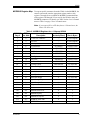
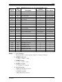
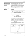
5/5/00
MODBUS
Communications for
the GF868
Your Model GF868 hardware and software have been modified to
provide MODBUS communications. The MODBUS option card
(703-1358) provides an RS485 interface with a host system, while the
main circuit board continues to support RS232 communications for
use with a PC running Panametrics’ IDM software.
To properly set up the instrument, use this addendum along with the
standard GF868 flowmeter User’s Manual (910-194). This document
shows how to install the MODBUS option card and how to program
the modified GF868 to access this special feature.
Installing the MODBUS
Option Card
IMPORTANT: The installation information presented here
supersedes the information in the standard GF868
User’s Manual.
The modified GF868 uses the RS485 standard for MODBUS
communications. This standard allows up to 32 nodes (drivers and
receivers) on one multidrop network, at distances up to 4,000 ft
(1,200 m). To connect the instrument(s) to the host system,
Panametrics recommends using a 24-gauge (24 AWG) twisted-pair
cable with a characteristic impedance of 120 ohms and a 120-ohm
termination at each end of the communications line.
The MODBUS option card must be plugged into either slot 5 or slot 6
of the GF868. On the option card, pin 1 is the [TMT-] inverting or
negative connection and pin 2 is the [TMT+] non-inverting or positive
connection. To link the GF868 to the control system, connect the two
wires of the twisted-pair cable from these terminals to the
corresponding terminals at the control system.
Note: If two MODBUS option cards are installed in the GF868, only
the card in slot 5 is activated.
Setting Up MODBUS
Communications
To set up MODBUS communications, enter the User Program as
described in your User’s Manual. Then, refer to the menu map in
Figure 1 on page 7 and complete the following steps:
Note: Any time the following settings are changed, the GF868 must
be rebooted to load the new settings into the option card.
Start É
PROGRAM
PROGRAM
status
ACTIV
913-257A
SYSTM
PIPE
I/O
Press the [→] key and then the
[F3] key to select the COMM
submenu. (On a two-channel
GF868, pressing the [→] key and
the [F3] key accesses the GLOBL
menu. Then press [F4] to select
the COMM submenu.)
1
5/5/00
Setting Up MODBUS
Communications
(cont.)
IMPORTANT: The serial port settings of the GF868 must match
those of the MODBUS control system.
É
COMM PROGRAM
PROGRAM
Comm port
BAUD RATE
current value appears here
4800
9600
[This baud rate applies only to
the RS232 serial port.] Press the
[→] until the desired RS232
baud rate appears on the option
bar and press the appropriate [Fx]
function key to select it.
19200
The available RS232 baud rates are 300, 600, 1200, 2400, 4800,
9600, and 19200.
É
COMM PROGRAM
BAUD RATE
current value appears here
UART bits
current setting appears here
8,no
8,odd
8even
7,no
[The UART bits setting applies
only to the RS232 serial port.]
Press the [→] until the desired
RS232 UART bits setting
appears on the option bar and
then press the appropriate [Fx]
function key to select it.
See Table 1 below for a description of the options available at the
above prompt.
Option Bar
Table 1: UART Bits Options
# Data Bits
# Stop Bits
Parity
8,no
8
0
None
8,odd
8
0
Odd
8even
8
0
Even
7,odd
7
1
Odd
7even
7
1
Even
COMM PROGRAM
UART bits
current setting appears here
Network I.D.?
current number appears here
[The Network ID number is used
by the IDM software only.] Enter
a Network ID number between 1
and 254 and then press [ENT].
The default ID number is 1.
Note: If more than one meter is connected to a network, each meter
must have a unique Network I.D.
913-257A
2
5/5/00
Setting Up MODBUS
Communications
(cont.)
COMM PROGRAM
Network I.D.?
current number appears here
Press the appropriate [Fx]
function key to select [2400],
[4800], or [9600] for the
MODBUS baud rate.
MODBUS BAUD RATE
current value appears here
2400
4800
9600
COMM PROGRAM
MODBUS BAUD RATE
current value appears here
Press the appropriate [Fx]
function key to select [NONE],
[ODD], or [EVEN] for the
MODBUS parity setting.
MODBUS PARITY
current setting appears here
none
odd
even
COMM PROGRAM
MODBUS PARITY
current setting appears here
Press the appropriate [Fx]
function key to select [1] or [2]
for the MODBUS stop bits
setting.
MODBUS STOP BITS
current setting appears here
1
2
COMM PROGRAM
MODBUS STOP BITS
current setting appears here
Enter a MODBUS Address
number between 1 and 247.
Then, press [ENT].
MODBUS Address?
current address appears here
Press [EXIT] until you return to RUN mode and the screen resumes the
display of data measurements. Then reboot the meter to load the new
settings into memory.
913-257A
3
5/5/00
MODBUS Register Map
To request specific parameters from the GF868 via the MODBUS, the
control system must enter the appropriate register number. Only
registers 1 through 90 are available for MODBUS communications,
while registers 508 through 512 are used by the GF868 to store the
MODBUS parameters. For details, see Table 2 below for a 1-Channel
meter or Table 3 on page 5 for a 2-Channel meter.
Note: If you request Ch2 or AVE data from a 1-Channel meter, the
values will all be zero.
Table 2: MODBUS Registers for a 1-Channel GF868
MODBUS
DPR
Scaling
Reg #
Hex Addr
Description
(decimal places)
Size in Bytes
1
0
1”
--
2 (16 bit signed)
2
2
Not Used
--
2 (16 bit signed)
3
4
Velocity
2
4 (2 16-bit int)
5
8
Act Volumetric
#Q DIGITS
4 (IEEE 32 bit)
7
C
Std Volumetric
#Q DIGITS
4 (IEEE 32 bit)
9
10
Fwd Totals
#T DIGITS
4 (2 16 bit int)
11
14
Rev Totals
#T DIGITS
4 (2 16 bit int)
13
18
#Tot Digits
0
2
14
1A
Mass Flow
#M DIGITS
4 (IEEE 32 bit)
16
1E
Fwd Mass Totals
#MT DIGITS
4 (2 16-bit int)
18
22
Rev Mass Totals
#MT DIGITS
4 (2 16-bit int)
20
26
#Mass Tot Digits
0
2
21
28
Timer
2
4 (2 16-bit int)
23
2C
Error Code
0
2
24
2E
Sound Speed
3
4 (2 16-bit int)
26
32
Molecular Weight
4
4 (2 16-bit int)
28
36
Signal Strength Upstream
1
4 (2 16-bit int)
30
3A
Signal Strength Downstream
1
4 (2 16-bit int)
32
3E
Temperature
2
4 (2 16-bit int)
34
42
Pressure
3
4 (2 16-bit int)
508
3F6
2
MODBUS baud rate
0
2
509
3F8
3
MODBUS parity
0
2
510
3FA
4
MODBUS stop bits
0
2
511
3FC
MODBUS meter addr
0
2
512
3FE
RESERVED
---
---
913-257A
Clear Ch1 Totalizers”
4
5/5/00
Table 3: MODBUS Registers for a 2-Channel GF868
MODBUS
DPR
Scaling
Reg #
Hex Addr
Description
(decimal places)
Size in Bytes
1
0
1”
2
2
1“Clear
3
4
Ch1 Velocity
5
8
7
--
2 (16 bit signed)
--
2 (16 bit signed)
2
4 (2 16-bit int)
Ch1 Act Volumetric
#Q DIGITS
4 (IEEE 32 bit)
C
Ch1 Std Volumetric
#Q DIGITS
4 (IEEE 32 bit)
9
10
Ch1 Fwd Totals
#T DIGITS
4 (2 16 bit int)
11
14
Ch1 Rev Totals
#T DIGITS
4 (2 16 bit int)
13
18
Ch1 #Tot Digits
0
2
14
1A
Ch1 Mass Flow
#M DIGITS
4 (IEEE 32 bit)
16
1E
Ch1 Fwd Mass Totals
#MT DIGITS
4 (2 16-bit int)
18
22
Ch1 Rev Mass Totals
#MT DIGITS
4 (2 16-bit int)
20
26
Ch1 #Mass Tot Digits
0
2
21
28
Ch1 Timer
2
4 (2 16-bit int)
23
2C
Ch1 Error Code
0
2
24
2E
Ch1 Sound Speed
3
4 (2 16-bit int)
26
32
Ch1 Molecular Weight
4
4 (2 16-bit int)
28
36
Ch1 Sig Strength Upstream
1
4 (2 16-bit int)
30
3A
Ch1 Sig Strength Downstream
1
4 (2 16-bit int)
32
3E
Ch1 Temperature
2
4 (2 16-bit int)
34
42
Ch1 Pressure
3
4 (2 16-bit int)
36
46
Ch2 Velocity
2
4 (2 16-bit int)
38
4A
Ch2 Act Volumetric
#Q DIGITS
4 (IEEE 32 bit)
40
4E
Ch2 Std Volumetric
#Q DIGITS
4 (IEEE 32 bit)
42
52
Ch2 Fwd Totals
#T DIGITS
4 (2 16 bit int)
44
56
Ch2 Rev Totals
#T DIGITS
4 (2 16 bit int)
46
5A
Ch2 #Tot Digits
0
2
47
5C
Ch2 Mass Flow
#M DIGITS
4 (IEEE 32 bit)
49
60
Ch2 Fwd Mass Totals
#MT DIGITS
4 (2 16-bit int)
51
64
Ch2 Rev Mass Totals
#MT DIGITS
4 (2 16-bit int)
53
68
Ch2 #Mass Tot Digits
0
2
54
6A
Ch2 Timer
2
4 (2 16-bit int)
56
6E
Ch2 Error Code
0
2
57
70
Ch2 Sound Speed
3
4 (2 16-bit int)
59
74
Ch2 Molecular Weight
4
4 (2 16-bit int)
913-257A
Clear Ch1 Totalizers”
Ch2 Totalizers”
5
5/5/00
Table 3: MODBUS Registers for a 2-Channel GF868 (cont.)
MODBUS
DPR
Scaling
Reg #
Hex Addr
Description
(decimal places)
Size in Bytes
61
78
Ch2 Sig Strength Upstream
1
4 (2 16-bit int)
63
7C
Ch2 Sig Strength Downstream
1
4 (2 16-bit int)
65
80
Ch2 Temperature
2
4 (2 16-bit int)
67
84
Ch2 Pressure
3
4 (2 16-bit int)
69
88
Avg Velocity
2
4 (2 16-bit int)
71
8C
Avg Act Volumetric
#Q DIGITS
4 (IEEE 32 bit)
73
90
Avg Std Volumetric
#Q DIGITS
4 (IEEE 32 bit)
75
94
Avg Fwd Totals
#T DIGITS
4 (2 16 bit int)
77
98
Avg Rev Totals
#T DIGITS
4 (2 16 bit int)
79
9C
Avg #Tot Digits
0
2
80
9E
Avg Mass Flow
#M DIGITS
4 (IEEE 32 bit)
82
A2
Avg Fwd Mass Totals
#MT DIGITS
4 (2 16-bit int)
84
A6
Avg Rev Mass Totals
#MT DIGITS
4 (2 16-bit int)
86
AA
Avg #Mass Tot Digits
0
2
87
AC
Avg Timer
2
4 (2 16-bit int)
89
B0
5
Avg Error Code
0
2
90
B2
Avg Sound Speed
3
4 (2 16-bit int)
508
3F6
2
0
2
509
3F8
3MODBUS
0
2
510
3FA
4
MODBUS stop bits
0
2
511
3FC
MODBUS meter addr
0
2
512
3FE
RESERVED
---
---
Notes:
MODBUS baud rate
parity
1. Clear Totalizers:
flag from the 8051 to clear either the Channel 1 or Channel 2 totalizers.
2. MODBUS baud rate:
5 = 2400, 6 = 4800, 7 = 9600
3. MODBUS parity:
0 = none, 1 = odd, 2 = even
4. MODBUS stop bits:
1 = 1 stop bit, 2 = 2 stop bits
5. AVG Error Code:
0=Both Ch1 and Ch2 are in error.
1=Ch1 only is in error
2=Ch2 only is in error
3=Both channels are error free
913-257A
6
5/5/00
1-Ch Meter 2-Ch Meter
GLOBL
COMM
Baud Rate (RS232)
F1
300
F2
600
F3
F4
F1
F2
1200
2400
4800
9600
F3
19200
UART Bits (RS232)
F1
F2
8,no
8,odd
F3
F4
7,odd
8even
F1
7even
Network I.D.?
MODBUS Baud Rate
F1
F2
F3
2400
4800
9600
MODBUS Parity
F1
F2
NONE
F3
ODD
EVEN
MODBUS Stop Bits
F1
1
F2
2
MODBUS Address
NOTE: Plain text represents prompt area messages and
boxed text represents option bar choices.
Fx represent function keys to select option bar choices.
Figure 1: MODBUS Menu Map
913-257A
7