1
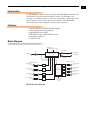
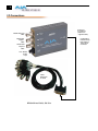
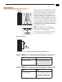
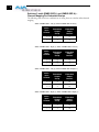
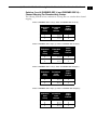
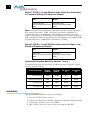
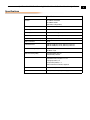
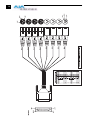
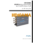
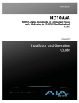
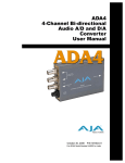
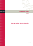
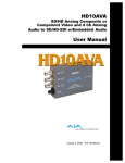
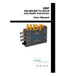
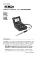
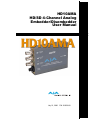
HD10AMA
HD/SD 4-Channel Analog
Embedder/Disembedder
User Manual
July 21, 2006
P/N 101659-00
2
Trademarks
AJA, Io, and Kona are trademarks of AJA Video, Inc. All other trademarks are the property of their
respective holders.
Notice
Copyright © 2006 AJA Video, Inc. All rights reserved. All information in this manual is subject to
change without notice. No part of the document may be reproduced or transmitted in any form,
or by any means, electronic or mechanical, including photocopying or recording, without the
express written permission of AJA Inc.
FCC Emission Information
This equipment has been tested and found to comply with the limits for a Class A digital device,
pursuant to Part 15 of the FCC Rules. These limits are designed to provide reasonable protection
against harmful interference when the equipment is operated in a commercial environment. This
equipment generates, uses and can radiate radio frequency energy and, if not installed and used in
accordance with the instruction manual, may cause harmful interference to radio
communications. Operation of this equipment in a residential area is likely to cause harmful
interference in which case the user will be required to correct the interference at his own expense.
Changes or modifications not expressly approved by AJA Video can effect emission compliance
and could void the user’s authority to operate this equipment.
Contacting Support
To contact AJA Video for sales or support, use any of the following methods:
443 Crown Point Circle, Grass Valley, CA. 95945 USA
Telephone: +1.800.251.4224 or +1.530.274.2048
Fax: +1.530.274.9442
Web: http://www.aja.com
Support Email: [email protected]
Sales Email: [email protected]
When calling for support, have all information on the product (serial number etc.) at hand prior to
calling.
Limited Warranty
AJA Video warrants that this product will be free from defects in materials and workmanship for a period of five years from
the date of purchase. If a product proves to be defective during this warranty period, AJA Video, at its option, will either
repair the defective product without charge for parts and labor, or will provide a replacement in exchange for the defective
product.
In order to obtain service under this warranty, you the Customer, must notify AJA Video of the defect before the expiration
of the warranty period and make suitable arrangements for the performance of service. The Customer shall be responsible
for packaging and shipping the defective product to a designated service center nominated by AJA Video, with shipping
charges prepaid. AJA Video shall pay for the return of the product to the Customer if the shipment is to a location within
the country in which the AJA Video service center is located. Customer shall be responsible for paying all shipping charges,
insurance, duties, taxes, and any other charges for products returned to any other locations.
This warranty shall not apply to any defect, failure or damage caused by improper use or improper or inadequate
maintenance and care. AJA Video shall not be obligated to furnish service under this warranty a) to repair damage resulting
from attempts by personnel other than AJA Video representatives to install, repair or service the product, b) to repair
damage resulting from improper use or connection to incompatible equipment, c) to repair any damage or malfunction
caused by the use of non-AJA Video parts or supplies, or d) to service a product that has been modified or integrated with
other products when the effect of such a modification or integration increases the time or difficulty of servicing the
product.
THIS WARRANTY IS GIVEN BY AJA VIDEO IN LIEU OF ANY OTHER WARRANTIES, EXPRESS OR
IMPLIED. AJA VIDEO AND ITS VENDORS DISCLAIM ANY IMPLIED WARRANTIES OF
MERCHANTABILITY OR FITNESS FOR A PARTICULAR PURPOSE. AJA VIDEO’S RESPONSIBILITY TO
REPAIR OR REPLACE DEFECTIVE PRODUCTS IS THE WHOLE AND EXCLUSIVE REMEDY PROVIDED TO
THE CUSTOMER FOR ANY INDIRECT, SPECIAL, INCIDENTAL OR CONSEQUENTIAL DAMAGES
IRRESPECTIVE OF WHETHER AJA VIDEO OR THE VENDOR HAS ADVANCE NOTICE OF THE
POSSIBILITY OF SUCH DAMAGES.
AJA HD10AMA HD/SD 4-Ch Analog Embedder/Disembedder User Manual — Introduction
Introduction
The HD10AMA is a dual rate 4 channel analog audio Embedder/Disembedder. The
Disembedder is always functional providing 4 outputs. The Embedder is user
selectable, on a channel pair basis, to either “pass” input audio or embed input audio
from the breakout cable. Analog audio levels are selectable. The HD10AMA
automatically detects and configures to the input video standard.
Features
• Dual rate HD-SDI/SDI Embedder/Disembedder
• 4 Channel Balanced Analog Audio I/O
• Supplied XLR breakout cable
• HD-SDI/SDI input, 2 HD-SDI/SDI outputs
• Dipswitch configuration
• 5-18VDC Power
1
Block Diagram
Embed 1/2, 3/4
Embed to Group 1,2,3,4
Cable Driver
EQ
HD-SDI Out 1
Embed and Pass-through
Packet Processor
HD-SDI In
HD-SDI Out 2
Cable Driver
XLR Breakout Cable
XLR Breakout Cable
Analog Input 1
(Ch 1)
ADC
Analog Input 2
(Ch 2)
ADC
Analog Input 3
(Ch 3)
ADC
Analog Input 4
(Ch 4)
ADC
HD10AMA, Block Diagram
DisEmbedder
Disembed
from Group
1,2,3,4
DAC
Analog Output 1
(Ch 1)
DAC
Analog Output 2
(Ch 2)
DAC
Analog Output 3
(Ch 3)
DAC
Analog Output 4
(Ch 4)
3
4
I/O Connections
Analog I/O
D-connector
(attaches to
supplied cable)
HD/SD-SDI Input
BNC
Configuration
Determined by
DIP switch on
other side of
Converter
HD/SD-SDI
Output 1
BNC
HD/SD-SDI
Output 2
BNC
+ 5 to 18VDC
Power
Input
Cable
Not Shown
To Scale
HD10AMA and Cable, Side View
AJA HD10AMA HD/SD 4-Ch Analog Embedder/Disembedder User Manual — User Controls
User Controls
The user interface for the HD10AMA is an 8-switch
DIP accessible through a cut-out in the bottom of
the unit. Use the DIP switches to configure how the
Analog embedding and disembedding functions.
There is also a jumper on the internal circuit board,
accessible by removing the outer shell case of the
HD10AMA. Located by the DIP switch, this jumper
is used in conjunction with the DIP switches 1 and 2
to select certain functions. The factory default setting
for the AUX jumper is “OPEN”. To remove the case
shell, simply remove the four phillips
1 screws that
fasten the back half of the case shell (the half having
the DIP switch access hole).
DIP Switch Setting
LEFT
RIGHT
1
2
3
4
5
6
7
8
Note: The combination of the AUX jumper
setting and the DIP switch settings determines the
overall operation of the HD10AMA.
The exact function of each DIP switch and what it
controls is described on the following pages.
DIP Switch Settings
1
2
3
4
5
6
7
Place AUX Jumper
Here to CLOSE
(Factory Default is OPEN)
8
AUX Jumper (Accessed On Circuit Board Inside The HD10AMA Case)
Switch 1 (EMBD 1/2)—Controls Audio Embedding for Channels 1/2
:
LEFT
RIGHT
Overwrite or embed new
channel 1/2 packets
If AUX Jumper is OPEN: Pass any
channel 1/2 packets on input SDI.
If AUX Jumper is CLOSED: Delete
all channel 1/2 packets from input
SDI.
Switch 2 (EMBD 3/4)—Controls Audio Embedding for Channels 3/4
:
LEFT
RIGHT
Overwrite or embed new
channel 3/4 packets
If AUX Jumper is OPEN: Pass any
channel 3/4 packets on input SDI.
If AUX Jumper is CLOSED: Delete
all channel 3/4 packets from input
SDI.
5
6
Switches 3 and 4 (EMBD GRP L) and (EMBD GRP H)—
Channel Mapping For Embedded Groups
The following tables show how combinations of setting these two switches affects channel
mapping.
Switch 3: EMBD GRP L Left (0), Switch 4: EMBD GRP H Left (0)
Audio
Input
Channel
1 —>
2 —>
3 —>
4 —>
SDI
Embedded
Output
Group
SDI
Embedded
Output
Channel
1
1
1
1
1
2
3
4
Switch 3: EMBD GRP L Right (1), Switch 4: EMBD GRP H Left (0)
Audio
Input
Channel
1 —>
2 —>
3 —>
4 —>
SDI
Embedded
Output
Group
SDI
Embedded
Output
Channel
2
2
2
2
5
6
7
8
Switch 3: EMBD GRP L Left (0), Switch 4: EMBD GRP H RIght (1)
Audio
Input
Channel
1 —>
2 —>
3 —>
4 —>
SDI
Embedded
Output
Group
SDI
Embedded
Output
Channel
3
3
3
3
9
10
11
12
Switch 3: EMBD GRP L Right (1), Switch 4: EMBD GRP H Right (1)
Audio
Input
Channel
1 —>
2 —>
3 —>
4 —>
SDI
Embedded
Output
Group
SDI
Embedded
Output
Channel
4
4
4
4
13
14
15
16
AJA HD10AMA HD/SD 4-Ch Analog Embedder/Disembedder User Manual — User Controls
Switches 5 and 6 (DISEMBD GRP L) and (DISEMBD GRP H)—
Channel Mapping For Disembedding Groups
The following tables show how combinations of setting these two switches affects channel
mapping.
Switch 5: DISEMBD GRP L Left (0), Switch 6: DISEMBD GRP H Left (0)
SDI
Embedded
Input
Group
1
1
1
1
SDI
Embedded
Input
Channel
1 —>
2 —>
3 —>
4 —>
Audio
Output
Channel
1
2
3
4
1
Switch 5: DISEMBD GRP L Right (1), Switch 6: DISEMBD GRP H Left (0)
SDI
Embedded
Input
Group
2
2
2
2
SDI
Embedded
Input
Channel
5 —>
6 —>
7 —>
8 —>
Audio
Output
Channel
1
2
3
4
Switch 5: DISEMBD GRP L Left (0), Switch 6: DISEMBD GRP H RIght (1)
SDI
Embedded
Input
Group
3
3
3
3
SDI
Embedded
Input
Channel
9 —>
10 —>
11 —>
12 —>
Audio
Output
Channel
1
2
3
4
Switch 5: DISEMBD GRP L Right (1), Switch 6: DISEMBD GRP H Right (1)
SDI
Embedded
Input
Group
4
4
4
4
SDI
Embedded
Input
Channel
13 —>
14 —>
15 —>
16 —>
Audio
Output
Channel
1
2
3
4
7
8
Switch 7 (LEVEL)—Control Whether Audio Levels are Professional
Or Consumer. Affects all 4 Inputs and Outputs
:
LEFT
RIGHT
Professional Levels
(See I/O Level Selection Matrix
Table)
Consumer Levels
(See I/O Level Selection Matrix
Table)
Note: Professional audio equipment has much higher levels than consumer equipment: a
0 VU reading corresponds to +4 dBu. Connecting a professional +4 dBu device to a
consumer audio input (-7 to -8 dBu) may produce dangerous overloading, whereas the
output of a consumer device probably does not have sufficient power to drive a professional
audio input. With consumer and semi-professional audio equipment, a VU reading of 0 dB
is typically referenced to -10 dBV, which is equivalent to -7.78 dBu.
Switch 8 (LEVEL)—Control Whether Audio Levels are High or Low.
Affects all 4 Inputs and Outputs
LEFT
RIGHT
High Levels
(See I/O Level Selection Matrix
Table)
Low Levels
(See I/O Level Selection Matrix
Table)
Output Level Selection Matrix For Switches 7 and 8
The following table shows the combinations of DIP switch settings required to configure
the audio output levels shown.
Nominal
(-20dBFS)
Full Scale
(0dBFS)
DIP Switch
#7
DIP Switch
#8
Professional US
+4dBu
+24dBu
LEFT
LEFT
Professional European
-2dBu
+18dBu
LEFT
RIGHT
Consumer High
-8dBu
+12dBu
RIGHT
LEFT
Consumer Low
-14dBu
+6dBu
RIGHT
RIGHT
In/Out Level Range
Installation
Typically, HD10AMA installation consists of the following:
1.
2.
3.
4.
disconnect +5VDC from the converter
configure the DIP switch for the desired equipment configuration and video formats
connect video equipment to the converter BNCs
apply +5VDC power to the converter (AJA power supply model DWP)
AJA HD10AMA HD/SD 4-Ch Analog Embedder/Disembedder User Manual — Specifications
Specifications
Item
Specification
Formats
HD SMPTE 292/296M
SD SMPTE 259M
(Automatic Configuration)
Video Input
HD-SDI or SDI BNC
Video Outputs
HD-SDI or SDI, 2x BNC
Audio Inputs
4 x Balanced Analog Audio, XLR
Audio Outputs
4 x Balanced Analog Audio, XLR
Audio Levels (Full Scale Digital)
See Output Level Selection Matrix presented earlier
Audio Converters
24 bit
Embedded Audio
SMPTE 272M (SD): 20-bit, 48KHz synchronous
SMPTE 299M (HD): 24 bit, 48KHz synchronous
Video Processing Delay
HD Mode: 7µS
SD Mode: 19µS
Audio Processing Delay
Disembed Delay: 920 uS
Embed Delay: 1200uS
User Controls
External Dipswitch:
Embedder on/off, Ch pairs 1/2 - 3/4
Input group select, 1-4
Output Group Select, 1-4
Audio Level: Pro/Consumer, High/Low
Size
5.8" x 3.1" x 1 (147 x 79 x 25mm)
Power
5-18V, 5 watts. Requires power supply.
1
9
10