1
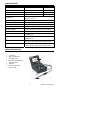
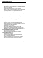
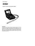
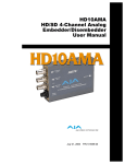
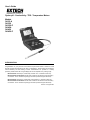
User's Guide
Oyster pH - Conductivity - TDS - Temperature Meters
Models
34135-A
341350
341350-P
34145A
341450
341450-P
INTRODUCTION
Congratulations on your purchase of the Extech's Oyster Series meter or meter kit. These
devices measure pH/Conductivity plus TDS or Temperature. These meters are intended for
routine laboratory and field testing. Accurate measurements are provided in a battery
operated, portable meter with a hinged display that can be adjusted to any viewing angle.
Model 34135-A measures pH, Conductivity and TDS. The ‘A’ indicates ‘meter-only’.
Models 341350 and 341350-P are kits which include the 34135A and all the necessary
accessories. The ‘P’ indicates Polymer type electrode (341350 has glass electrode).
Model 34145-A measures pH, Conductivity & Temperature. ‘A’ indicates ‘meter-only’.
Models 341450 and 341450-P are kits which include the 34145A and all the necessary
accessories. The ‘P’ indicates Polymer type electrode (341450 has glass electrode).
Version 1.5 August 2001
SPECIFICATIONS
Range (resolution)
Accuracy
± 0.5%
Conductivity
10 - 19,990µS (10µS)
Temperature (34145-A only)
-30 to 105 C
± 0.5 C
pH
0.00 to 14.00pH (0.01pH)
± 0.02pH
TDS (34135-A only)
10 - 19,990ppm (10ppm)
± 0.5%
Auto/Manual Temperature
Compensation
Manual for pH/Auto for conductivity/TDS; 0-100 C;
Correction: 2% per C
Power
9V battery or optional AC adapter
Display
3-1/2 Digit LCD (90 to 180 adjustable viewing angle)
Overrange Indication
Automatic (1---) on all ranges
Low Battery Indication
Automatic
o
0
o
o
o
Dimensions/Weight
3.75 x 4.25 x 2" (96 x 108 x 45mm) / 12 oz (340g)
Accessories supplied
9V battery, plus:
341350 kit pH electrode, pH buffers, bottle, case, glass
conductivity cell
341350-P pH electrode, pH buffers, bottle, case, polymer
conductivity cell
341450 kit pH electrode, pH buffers, bottle, case, glass
conductivity cell, stainless steel temperature probe
341450-P pH electrode, pH buffers, bottle, case, polymer
conductivity cell, stainless steel temperature probe
METER DESCRIPTION
1.
LCD display
2.
Battery compartment
3.
AC adapter input
4.
Electrode and Temperature
probe input jacks
5.
Electrode
6.
Neck-strap fasteners
7.
Function keys
1
2
3
4
7
6
5
2
Version 1.5 August 2001
OPERATING INSTRUCTIONS
pH Calibration
1.
Calibrate the meter and electrode before each use to ensure accuracy.
2.
Connect the pH electrode via the BNC connector to the meter.
3.
Open the meter to the fully extended position. Open the battery cover and install a 9V
battery. Replace the cover and turn the unit ON. The LCD indication should appear.
4.
Slide the SELECT switch to pH
5.
Adjust the TEMP C knob to approximate the solution temperature.
6.
Remove the wetting cap from the tip of the electrode. Rinse in de-ionized water, blot
dry and place the electrode in a 7.00 pH buffer solution. Allow to stand for
approximately one minute or until the display stabilizes.
o
7.
Adjust the CALIB knob until the display reads 7.00.
8.
Remove the electrode from the buffer and rinse it in distilled water and blot dry. Place
the electrode in a 4 or 10 pH buffer solution and allow to stand for approximately 1
minute or until the display stabilizes.
9.
Adjust the SLOPE knob until the display reads 4.00 or 10.00 (as required).
10. Repeat steps 6 through 9 until no further adjustment is necessary.
pH Measurement
1.
Place the electrode in the sample solution and read the pH value on the LCD.
2.
When all measurements have been taken, unplug the electrode or cell and rinse in
distilled water, shake and store as described below.
Conductivity / TDS Calibration
The conductivity cell calibration should be performed frequently to ensure accuracy.
1. Connect the conductivity cell to the input socket on the side of the meter.
2.
Prepare a conductivity solution of approximately the same value as the solution to be
0
measured. The solution should be prepared at 25 C.
3.
Set the meter to the uS/cm or TDS mode.
4.
Place the cell in calibration solution and allow the reading to stabilize.
5.
Adjust the Cell knob until the display reads the value of the calibration solution.
Example: For a 12560uS/cm conductivity solution the display will read 1256. The
user must multiply the reading x 10.
Conductivity/TDS Measurements (Multiply readings by 10)
1.
Place the electrode in the sample solution.
2.
When finished, unplug the electrode or cell and rinse in distilled water.
Temperature Measurement (34145-A only)
1.
Set the mode switch to Temperature.
2.
Connect the temperature probe to the meter via the meter’s phone jack.
3.
The LCD will indicate the temperature in C.
4.
Immerse the probe at least 1/3 of the way below the surface of the solution.
5.
Allow enough time for the electrode to reach the sample’s temperature.
o
3
Version 1.5 August 2001
Care of the Conductivity/TDS Cell
To prepare the cell, remove any outer protective sheath that may be used in shipping.
1. Cell Storage
On sheathed cells, replace the sheath over the cell when storing. For non-sheathed
versions, soak the cell tip in de-ionized water for storage.
2.
Cell Cleaning
After each use, the cell tip should be rinsed with de-ionized water. If solids build up
inside the cell carefully remove with a cotton swab soaked in solvent taking care not
to touch the metal parts of the inner cell.
3.
Internal Cell Elements
Two platinum plates reside on the inner cell wall. These plates should be a uniform
black color. If blemishes and scratches appear on these plates, the cell may need
repair. If this occurs, it is suggested that the cell be returned for evaluation.
Care of the pH Electrode
1.
The 60120B pH electrode is recessed in the polymer body allowing it to rest against
the bottom of a beaker without damage the glass bulb. This eliminates the need for
electrode holders and allows the probe to be used as a stirring rod. The sealed
reference design eliminates the need for filling solutions (minimizes "dry-out"). Up to
100 psig systems can be accommodated without external pressurization.
2.
The Electrode should remain in its bottle or cap until used. Afterwards, store the
Electrode in its bottle. Use a pH 4 buffer solution or tap water as the storage medium.
3.
If bubbles are seen in the bulb area, hold the electrode by its cap and shake
downwards until bubbles are removed.
4.
To improve speed of response, vigorously stir the electrode in the sample, buffer, or
rinse solution.
5.
After exposure to a sample, buffer, or rinse solution, shake the electrode with a snap
motion to remove residual drops of solution.
6.
Use part of the next sample/buffer to be measured as a rinse solution, when possible.
7.
When calibrating, use a buffer as close as possible to the expected pH of the sample.
8.
Keep buffers and samples at the same temperature to avoid temperature effects.
9.
pH readings stabilize faster in some solutions than others; allow time to stabilize.
10. Electrodes deteriorate over time. If accuracy falls to 10% the electrode should be
cleaned or replaced. If no improvement is observed, replace the electrode at once.
Electrode Storage
The electrode can be stored in the soaker bottle or wetting cap. For the storage bottle,
slide the cover onto the electrode, replace the O-ring, and insert electrode into bottle firmly
tightening the cap. Ensure that the bottle or cap is filled with a pH 4 buffer or tap water.
Electrode Cleaning
The type of electrode coating which occurs over time will determine the cleaning method.
Soft coatings can be removed by vigorous stirring or by the use of a squirt bottle. Organic
chemical (hard coatings) should be chemically removed. Only in extreme cases should the
bulb be cleaned mechanically.
4
Version 1.5 August 2001
pH Troubleshooting Chart
Symptom
Long response
time or reading
drift
Cause
Clogged Junction
Recommended Solution
o
Soak in 4.07 M KCL @ 60 C for 30
minutes
Strong Alkaline measurement
Soak in 0.1 M HCL overnight
Deteriorated Gel layer
Protein coating on electrode
surface
Soak in 1 gm Pepsin dissolved in
100ml of 0.1 m HCL for 30 minutes or
as needed
Oil, paint, dyes, suspended solids Rinse electrode alternately with
on sensor
materials solvent then buffer 7.00
Organic solvents are coating
sensor
Dehydrated membrane
Organic mole fraction has to be less
than 50% to assure reasonable
readings. Limit time of measurement.
Keep probe in the 7.0 buffer between
readings.
Dry Bulb
Long term storage without wetting Soak electrode tip in wetting cap filled
with 1ml 7.00 buffer for 24 to 48 hours
Static Charge
Wiping electrodes
Rinse electrode in 7.0 buffer and blot.
Do no wipe electrode.
Same readings in Cracked or broken bulb
different buffers
and samples
Replace electrode. Use bulb guard.
Avoid plunging electrode to bottom of
container and spinning bars. A
wetting cap will protect bulb between
measurements.
Erratic LCD
display
For each 50 ml of sample add 1 drop
(50uL) of SAT.KCL No alteration in
pH will occur by inert KCL.
Samples have low ionic strength
(lacks salt); e.g. distilled, deionized, boiled, lake water (high
pressure)
MAINTENANCE
Conductivity Cell Simulator
The meter is supplied with a cell simulator which can be used in place of the conductivity
cell to provide a means to verify the operation of the meter. The simulator will produce a
reading of approximately 800 - 1200uS (~1mS). The simulator should not be used as a
calibration device.
This device is helpful in determining if the cause of calibration difficulties is related to the
meter or (more likely) an aged or defective conductivity cell.
Battery Replacement
Install a new battery when the LOW BATTERY indication appears on the LCD. Remove
the battery cover (refer to Fig. 1 for location), install new battery, and replace cover.
Calibration / Repair Services
Extech offers complete repair and calibration services for all of the products we sell. For
periodic calibration, NIST certification or repair of any Extech product, call customer
service for details on services available. Extech recommends that calibration be performed
on an annual basis to insure calibration integrity.
5
Version 1.5 August 2001
REPAIR AND CALIBRATION SERVICES
Extech offers complete repair and calibration services for all Extech products. For
periodic calibration, NIST certification or repair of any Extech product, call customer
service for details on services available. Extech recommends that calibration be performed
on an annual basis.
WARRANTY
EXTECH INSTRUMENTS CORPORATION warrants this instrument to be free of defects in parts and
workmanship for one year from date of shipment (a six month limited warranty applies on sensors and
cables). If it should become necessary to return the instrument for service during or beyond the warranty
period, contact the Customer Service Department at (781) 890-7440 ext. 210 for authorization or visit our
website at www.extech.com (click on Contact Extech and go to Service Department to request an RA
number). A Return Authorization (RA) number must be issued before any product is returned to Extech. The
sender is responsible for shipping charges, freight, insurance and proper packaging to prevent damage in
transit. This warranty does not apply to defects resulting from action of the user such as misuse, improper
wiring, operation outside of specification, improper maintenance or repair, or unauthorized modification.
Extech specifically disclaims any implied warranties or merchantability or fitness for a specific purpose and
will not be liable for any direct, indirect, incidental or consequential damages. Extech's total liability is limited
to repair or replacement of the product. The warranty set forth above is inclusive and no other warranty,
whether written or oral, is expressed or implied.
Support Hotline (781) 890-7440
Tech support: Ext. 200; Email: [email protected]
Repair/Returns: Ext. 210; Email: [email protected]
Website: www.extech.com
Copyright © 2001 Extech Instruments Corporation. All rights reserved
including the right of reproduction in whole or in part in any form.
6
Version 1.5 August 2001