1
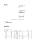
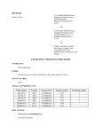
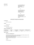
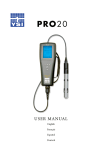
IOP:011.7B
IOP:011.2C
IOP:011.0D
Dissolved Oxygen Meters
IOP:011.7B
YSI Model 55 Dissolved Oxygen Meter
IOP:011.7B
U.S. Fish and Wildlife Service
Marquette Biological Station
3090 Wright Street
Marquette, Michigan 49855
U.S.A.
February 3, 2014
and
U.S. Fish and Wildlife Service
Ludington Biological Station
229 South Jebavy Drive
Ludington, Michigan 49431
U.S.A.
and
Department of Fisheries and Oceans
Sea Lamprey Control Centre
1219 Queen Street East
Sault Ste. Marie, Ontario P6A 2E5
Canada
INSTRUMENT OPERATING PROCEDURE
INSTRUMENT:
Dissolved oxygen meter
MODEL:
55
MANUFACTURER:
Yellow Springs Instrument Co., Inc.
SERIAL AND PROPERTY NOS:
Model number
Location
Serial number
Property number
Identifying number
55
55
55
55
55
55
MBS
MBS
MBS
MBS
SLCC
SLCC
97H1426AH
95H36679
02B0232AC
02B0232AH
4003224
5K2320AD
1030
386707
1580
1581
05-01
05-54
1
2
3
4
05-01
05-54
PRECAUTIONS:
POTENTIAL INTERFERENCES
Chlorine, sulfur dioxide, nitric oxide, and nitrous oxide can affect readings by behaving like oxygen at the
membrane. Static electricity may affect readings.
SAFETY
No special precautions
PROCEDURES:
I.
Meter preparation
A.
At initial set-up six AA-size batteries are installed.
1.
Use a screwdriver or coin to remove the thumbscrew on the bottom of the
meter.
2.
Open the battery-chamber cover.
3.
Install the batteries according to the label on the battery-chamber sleeves.
4.
Press and release the ON/OFF button on the front of the instrument. The LCD
will come on; if not, consult the troubleshooting guide.
5.
This procedure is also used when LO BAT appears on the LCD.
B.
Remove the probe from the calibration chamber and add 6-8 drops of distilled water into
the sponge on the bottom of the chamber. Turn the instrument over to allow excess
water to drain.
C.
Prepare the probe: this procedure is used at initial set-up and when membrane
replacement is necessary.
1.
Unscrew the probe sensor guard.
2.
Remove the O-ring and old membrane (if present).
3.
Rinse the sensor tip and KCl reservoir with distilled water.
4.
Prepare the electrolyte according to the directions on the KCl solution bottle.
5.
Install the membrane (YSI Model 5775 standard membrane; 1 mil
recommended).
a.
Secure a membrane between your thumb and the probe body. Add
electrolyte to the probe until a large meniscus completely covers the
gold cathode. Do not touch the center of the membrane.
b.
With the thumb and forefinger of your other hand, grasp the free end of
the membrane and with a continuous motion, stretch the membrane up,
over, and down the other side of the sensor. Stretching forms the
membrane to the contour of the sensor tip.
c.
Secure the end of the membrane under your forefinger while continuing
to hold the probe.
d.
e.
f.
II.
III.
Roll the O-ring over the end of the probe, while being careful not to
touch the membrane surface. Leave no wrinkles in the membrane or
trapped air bubbles under the membrane. Minor wrinkles may be
removed by lightly tugging on the edges of the membrane beyond the
O-ring.
Trim excess membrane from the probe with scissors or a sharp
knife. Check that the stainless steel temperature sensor is not covered
by excess membrane.
Shake off excess KCl and rinse the stainless steel thoroughly with
distilled water to prevent corrosion. Reinstall the sensor guard. Store
the sensor in a humid environment such as the calibration chamber
between measurements and when not in use.
Calibration
A.
Ensure that the sponge inside the instrument calibration chamber is wet. Insert the probe
into the calibration chamber.
B.
Turn the instrument on by pressing the ON/OFF button on the front of the instrument.
Wait a few minutes for the dissolved oxygen and temperature readings to stabilize.
C.
Use two fingers to press and release the two “up” and “down” arrow keys at the same
time.
D.
The LCD will prompt you to enter the local altitude in hundreds of feet. Use the arrow
keys to increase or decrease the altitude (example: entering the number 12 indicates 1200
feet). When the proper altitude appears on the LCD, press the ENTER key once to view
the calibration value and a second time to move to the salinity compensation procedure.
E.
The LCD will prompt you to enter the approximate salinity of the water you are about to
analyze. Use the arrow key to decrease the salinity compensation to 0 (fresh water
value). When 0 appears on the LCD, press the ENTER key.
F.
It may be necessary to re-calibrate the instrument each time the YSI Model 55 is turned
off. Complete all calibrations at a temperature as close as possible to the sample
temperature.
Oxygen measurement
A
Once the calibration is complete, the only keys which will remain operational are the
MODE key, the LIGHT key, and the ON/OFF key.
B.
Place the probe in the water. When measuring oxygen concentration of stream water,
immerse the probe in slow moving water away from riffles or highly aerated areas.
C.
Slowly move the probe to maintain movement of water across the membrane. Stream
current furnishes sufficient movement when measuring the oxygen content of stream
water.
D.
Allow sufficient time for the probe to stabilize before measuring temperature and
dissolved oxygen concentration.
E.
Move between the mg/L and % air saturation mode by pressing the MODE key; the
LIGHT key activates the back-light on the LCD.
F.
The ON/OFF key turns the instrument off.
IV.
Storage
A.
Turn the ON/OFF switch to OFF.
B.
Add a small quantity of deionized water to the sponge in the calibration chamber.
C.
Rinse probe with deionized water.
D.
Return the probe to the calibration chamber.
E.
Return the meter to the storage case and secure.
MAINTENANCE:
I.
Battery replacement - see section I.A.
II.
Membrane replacement - see section I.C.
REFERENCE:
Operations Manual YSI Model 55 Handheld Dissolved Oxygen System
This procedure has been reviewed and approved by the undersigned representatives of the U.S.
Fish and Wildlife Service and Fisheries and Oceans Canada.
REVIEWED/APPROVED______________________________
Field Supervisor (U.S.)
DATE____________
REVIEWED/APPROVED______________________________
Division Manager (Canada)
DATE____________
Attachments
YSI Model 55 Dissolved Oxygen Meters
DISSOLVED OXYGEN METER
YSI Model 55
Updated 2/2000:daj
Serial number
____________________________
Property number
____________________________
Unit number
____________________________
Location
____________________________
Date
Time
Initials
Stream
Temp.
(C0)
Calibration
value
Remarks and maintenance
SEA LAMPREY CONTROL PROGRAM
DOCUMENTATION OF INITIALS
(All personnel trained to operate this instrument must sign and initial this form)
OPERATOR
INITIALS
IOP:11.2C
YSI Model Pro 20 Oxygen Meters
IOP:011.2C
U.S. Fish and Wildlife Service
Marquette Biological Station
3090 Wright Street
Marquette, Michigan 49855
U.S.A.
February 3, 2014
and
U.S. Fish and Wildlife Service
Ludington Biological Station
229 South Jebavy Drive
Ludington, Michigan 49431
and
Fisheries and Oceans Canada
Sea Lamprey Control Centre
1219 Queen Street East
Sault Ste. Marie, Ontario P6A 2E5
Canada
INSTRUMENT OPERATING PROCEDURE
INSTRUMENT:
Dissolved oxygen meter
MODEL:
Pro 20
MANUFACTURER:
Yellow Springs Instrument Co., Inc.
SERIAL AND PROPERTY NOS:
Model Number
Location
Serial number
Property number
Identifying number
Pro 20
Pro 20
Pro 20
Pro 20
Pro 20
Pro 20
SLCC
SLCC
SLCC
MBS
MBS
LBS
11G101544
11J10029
13A102273
09M100314
09M100315
10D100417
11-54
11-53
12-29
3139
3140
LFY10-182
11-54
11-53
12-29
Base 1
Base 2
1
Pro 20
Pro 20
Pro 20
LBS
LBS
LBS
10D100419
13A101464
13A101645
LFY10-183
13-004
13-005
2
3
4
PRECAUTIONS:
POTENTIAL INTERFERENCES
Chlorine, sulfur dioxide, nitric oxide, and nitrous oxide can affect readings by behaving like oxygen at
membrane. Static electricity may affect readings.
Gold Cathode - The gold cathode on the sensor must be textured properly. It may becomes tarnished or
plated with silver after extended periods of use.
Bubbles under the membrane cap.
Remove excessive water in calibration/storage sleeve.
SAFETY
No Special precautions
PROCEDURES:
I.
Meter preparation and maintenance
A.
Program the DO meter to allow it to recognize the Poloragraphic 2003 model probe
(engraved on the side of sensor body). See the system setup menu section of the Pro20
Instruction Manual for directions. This procedure is done only during initial setup or
when changing probe models.
B.
Battery installation or replacement of two alkaline C-size batteries.
C.
1.
Use a screwdriver to remove the 4 screws on the back cover of the meter.
2.
Lift off the battery-chamber cover.
3.
Install the batteries according to the inscribed battery symbols on the inside of
the battery chamber. Make sure batteries are in correct polarity.
4.
Close the battery chamber cover and secure cover with the 4 screws.
5.
Press and release the ON/OFF button (☼) on the front of the instrument. The
LCD will come on; if not, consult the trouble shooting guide in the Pro 20
Instruction Manual.
6.
A battery symbol will appear in the lower, left corner of the display to indicate
low batteries when about 1 hour of battery life remains.
7.
Follow this procedure when the low battery symbol appears in the display.
8.
To turn off the unit, press and hold the power /backlight key for three seconds.
Connect the cable/probe assembly to the meter.
1.
Align the keys in the cable connector to the slots in the meter connector.
2.
Push together and twist the outer ring clockwise until it locks into place.
3.
To remove the probe, twist the outer ring until keys and slots are aligned and
then pull apart the connectors.
D.
E.
F.
Initial sensor installation and maintenance. This section can be skipped if not replacing a
sensor.
1.
Remove/unscrew the metal guard.
2.
To properly install a new sensor, insure that both the sensor connector and
sensor port on the cable stay dry during this entire procedure.
3.
If replacing the old sensor, remove it by twisting the sensor counter-clockwise.
4.
Align the pin in the bulkhead and the sensor connector and push the sensor into
the connector on the cable until it is firmly seated and only 1 o-ring is visible on
the sensor.
5.
Twist the sensor clockwise to engage threads and finger tighten.
6.
Replace the metal guard.
Sensor membrane installation maintenance.
1.
Change membrane and oxygen probe electrolyte solution every 30 days.
2.
Remove the metal sensor guard.
3.
If installing a membrane for the first time, remove the protective cap or remove
the old membrane cap by unscrewing it with the probe upside down.
4.
Examine the gold cathode at the tip of the sensor and silver anode along the
shaft of the sensor. If either the silver anode is black in color or the gold
cathode is dull (tarnished), the sensor needs maintenance or replacement. Refer
to the Pro20 Instruction Manual, GENERAL MAINTENANCE, of
polarographic sensor (Model # 605203).
5.
Rinse the sensor with de-ionized water.
6.
Fill a new membrane cap (5908 Kit - Yellow, 1.25 mil polyethylene) with
oxygen probe electrolyte Solution. Do not touch the membrane surface.
7.
Tap the side of the membrane cap to release air bubbles.
8.
Thread the membrane cap onto the sensor with the probe upside down.
9.
Replace the metal sensor guard.
Storage of the DO probe.
1.
Short term storage (30 days or less), slide probe into soft plastic
calibration/storage sleeve. Make sure there is a small amount of moisture (tap
water) on a sponge in the sleeve.
2.
II.
Pro20 Key Pad Functions.
A.
III.
Long term storage, store sensor in a dry state.
a.
Remove the membrane cap.
b.
Thoroughly rinse the sensor with water.
c.
Let sensor air dry, completely.
d.
Use a clean dry membrane cap and screw over the sensor to keep it dry
and protected.
e.
Store at -5 to 70C.
Refer to the Pro20 Instruction Manual to setup meter configuration prior to initial use.
1.
Backlight key (☼); after the unit is turned on, press the star key. The backlight
will remain on for 2 minutes unless the star key is pressed again.
2.
Navigation; the up ▲ and down ▼ arrow keys allow you to navigate the
highlighted box at the bottom of the display. In the Menu, the arrow keys will
also move the highlight bar up and down.
3.
Accessing highlighted options; use the ENTER ◄--- key.
4.
Calibration key; Cal, used for calibrating the meter.
5.
The menu key, used for accessing the system setup functions.
Calibration
A.
Ensure that the following is completed before calibrating; the barometer is reading
accurately and the sponge is wet in the probe calibration/sleeve. If the auto shutoff is
already set for 20 minutes or more this section can be skipped.
1.
Power the meter on and wait 10 to 15 minutes.
2.
The auto shut off timer should be disabled or set to at least 20 minutes.
3.
Press Menu on the keypad.
4.
Scroll down to Auto Shutoff.
5.
Press ENTER ◄--, Time in Minutes will appear.
6.
Press ENTER ◄--, This will allow the meter to select the amount of minutes
before meter will shut off.
7.
Select the desired amount of minutes by scrolling ▲ up or ▼ down to increase
the minutes or decrease the number of minutes.
8.
Press ENTER ◄--, to exit Time in Minutes. The ESC (exit) box will be
highlighted.
9.
Press ENTER ◄--, ENTER ◄--, to return to the running screen.
B.
C.
One Touch Calibration Method (for % DO). Calibrate the meter in % dissolved oxygen
to insure accuracy in the following steps of section B and C. This method does not let
you see the calibration value to record it.
1.
Power the meter on and wait for 10 to 15 minutes, if meter is not already turned
on.
2.
3.
Adjust the auto shut off to at least 20 minutes if not already done. See section
Calibration can be done by selecting Menu on the key pad.
4.
Scroll down, select the One Touch Calibration method.
5.
Then scroll down and select ESC box at the bottom of the display by pressing
the Enter ◄--. Skip steps 2, 3, and 4 after configuring the meter for future One
Touch Calibrations.
6.
Press and hold the Cal key for three seconds. The words Calibrating % DO will
be displayed.
7.
When the calibration is completed, the phrase Calibration Successful will appear
in a highlighted box on the display for a few seconds. Then the instrument will
return to the run screen.
8.
If unsuccessful, an error message will appear on the screen. Press the Cal key to
exit the calibration error message and return to the run screen. See the trouble
shooting guide in the Instruction Manual for a possible solution.
Normal Calibration Method (for % DO). This is the preferred method. Recording
calibration values in this Instrument Operation Manual is required by the Standard
Operating Procedures.
1.
Select Menu on the meter keypad.
2.
Scroll down and de-select the One Touch Calibration Method by pressing Enter
◄-- when highlighted.
3.
Scroll down to and select the Esc box at the bottom of the display. The run
screen should now be displayed.
4.
Press and hold the Cal key for three seconds.
5.
Scroll to select a calibration mode, either calibrate in ppm or %, Select %.
6.
Press ENTER ◄--. The meter will display a calibration value, temperature in
degrees C, and the % air saturation. The Calibration Value is base on the
current barometric pressure. Wait at least three seconds, then record the
information in the SOP log book.
7.
Press Enter ◄--. Calibration Successful should be displayed on the screen for 3
seconds.
8.
If Unstable Reading is displayed on the screen, press Cal on the key pad to
cancel calibration and repeat procedure.
9.
The meter will return to the run screen. If an error occurred, check the
troubleshooting guide for a possible solution.
IV.
Measurements
A.
Insure the cable/probe is connected to the meter.
B.
Be sure the YSI Pro20 DO Meter has been calibrated.
C.
Turn the instrument on and wait 10-15 minutes while the probe remains in the
calibration/storage sleeve.
D.
Place the probe in the sample to be measured.
E.
Shake the probe in the sample to release air bubbles.
F.
Allow temperature reading to stabilize.
G.
Stir the sample water with the probe at a moderate pace. You must provide 6 inches of
water movement per second across the sensor membrane to obtain an accurate reading.
Be careful not to create a vortex which allows air bubbles to pass against the membrane.
H.
When the % DO value is stabilized, record the measurement.
I.
The DO values will decrease if stirring ceases.
MAINTENANCE:
See instrument manual.
REFERENCE:
User Manual YSI Model Pro20 Handheld Dissolved Oxygen Meter System
This procedure has been reviewed and approved by the undersigned representatives of the U.S.
Fish and Wildlife Service and Fisheries and Oceans Canada.
REVIEWED/APPROVED______________________________
Field Supervisor (U.S.)
DATE____________
REVIEWED/APPROVED______________________________
Division Manager (Canada)
DATE____________
Attachments
YSI Model Pro 20 Dissolved Oxygen Meters
DISSOLVED OXYGEN METER
YSI Model Pro 20
Serial number
____________________________
Property number
____________________________
Unit number
____________________________
Location
____________________________
Date
Time
Initials
Stream
Temp.
(C0)
Calibration
value
Remarks and maintenance
SEA LAMPREY CONTROL PROGRAM
DOCUMENTATION OF INITIALS
(All personnel trained to operate this instrument must sign and initial this form)
OPERATOR
INITIALS
IOP:011.0D
Thermo Scientific Orion Star A223
Portable Dissolved Oxygen Meter
IOP:011.0D
U.S. Fish and Wildlife Service
Marquette Biological Station
3090 Wright Street
Marquette, Michigan 49855
U.S.A.
January 3, 2013
and
U.S. Fish and Wildlife Service
Ludington Biological Station
229 South Jebavy Drive
Ludington, Michigan 49431
and
Fisheries and Oceans Canada
Sea Lamprey Control Centre
1219 Queen Street East
Sault Ste. Marie, Ontario P6A 2E5
Canada
INSTRUMENT OPERATING PROCEDURE
INSTRUMENT:
Dissolved oxygen meter
MODEL:
Orion Star A223
MANUFACTURER:
Thermo Fisher Scientific Inc.
SERIAL AND PROPERTY NOS:
Model Number
Location
Serial number
Property number
Identifying number
Orion Star A223
MBS
K00334
3205
1
PRECAUTIONS:
POTENTIAL INTERFERENCES
Alcohols greater than 5% hydrogen peroxide, commercial bleach, gaseous chlorine, and gaseous sulfur
dioxide can affect readings. Static electricity may affect reading.
Excessive water in calibration/storage sleeve.
Note: The RDO cap is only good for 365 days. The countdown begins with first reading taken. Err 881
will appear when the RCO cap has expired.
SAFETY
No Special precautions
PROCEDURES:
I.
Meter preparation
A.
B.
Battery installation or replacement of four alkaline AA-size batteries.
1.
Use a screwdriver to remove the 2 screws on the back cover of the meter.
2.
Remove the battery-chamber cover.
3.
Install the batteries according to the inscribed battery symbols on the inside of
the battery chamber. Make sure batteries are in correct polarity.
4.
Close the battery chamber cover and secure cover with the 2 screws.
5.
Press and release the POWER button on the front of the instrument. The LCD
will come on; if not, the replacement batteries may be bad.
6.
A battery life indicator will appear in the upper, left corner of the display
showing the remaining battery power.
7.
To turn off the unit, press and hold the POWER button for three seconds.
Initial Sensor/Probe preparation
1.
NOTE:
1) Do not touch the bottom of the RDO cap, optical window or spring contacts
on the RDO sensor.
2) The silicone grease that is supplied with the RDO sensor should only be
used to lubricate the two O-rings on the RDO sensor. Do not fill the RDO
cap with the grease.
3) The RDO cap has an internal clock that counts down the 365 day lifespan of
a new cap. This countdown begins with the first measurement taken.
2.
Remove the protective shipping cap from the end of the RDO sensor.
3.
Lubricate the two O-rings on the RDO sensor with a thin film of the silicone
grease provided.
4.
Align the arrow on the RDO cap with the arrow on the RDO sensor.
5.
Slide and press the RDO cap onto the RDO sensor until the cap is flush with the
sensor body. (Do not twist the RDO cap. Once the cap is installed, it should
not be removed until a new cap is needed or troubleshooting needs to be
performed).
6.
Connect the RDO sensor to the 9 pin input on the meter. An Err 880 message
will appear if the sensor is not fully connected to the meter, and/or an Err 882
message will appear if the RDO cap is missing or not properly installed.
II.
III.
IV.
Calibration
A.
Remove the end cap from the calibration sleeve and remove the sponge from the
sleeve. Saturate the sponge with distilled water and squeeze the excess water out of the
sponge.
B.
Replace the sponge and the end cap.
C.
Turn power ON.
D.
Meter should now be in the measurement mode, press f1 to select cal.
E.
Use the up or down arrows to highlight Air and press f3 to select.
F.
Rinse probe with distilled water, blot dry with lint-free tissue, and attach
the calibration sleeve.
G.
Wait about 5 minutes for the RDO sensor to equilibrate.
H.
Press f3 (start).
I.
Wait for the DO reading on the meter to stabilize and stop flashing. Once the
reading is stable, the meter will display “Reading is stable. Accept auto calibration
value”.
J.
Press f2 (cal done).
K.
Press f1 (meas) to get into measurement mode.
Measurements
A.
Make sure the meter is reading in mg/l. This can be changed with the Mode button.
B.
Rinse probe with distilled water and blot dry.
C.
If measurements are to be taken directly from stream or lake, attach the stainless steel
protective guard, which also serves as a weight.
D.
Insert probe into sample or lower probe to desired depth and press Measure to start the
measurement.
E.
When the AR icon stops flashing, record the dissolved oxygen and temperature. Press
Measure again to start next measurement.
F.
When finished with final measurement, rinse probe with distilled water and return
probe to the calibration sleeve. And turn off meter.
Storage
A.
For short and long term storage, leave the RDO cap on the sensor, keep it in the
calibration sleeve, making sure to wet the sponge with distilled water, and keep the
sensor out of direct sunlight.
MAINTENANCE:
See instrument manual.
REFERENCE:
User Manual Thermo Scientific Orion Star A223 Portable RDO/DO Meter Instruction Sheet and User
Guide.
This procedure has been reviewed and approved by the undersigned representatives of the U.S.
Fish and Wildlife Service and Fisheries and Oceans Canada.
REVIEWED/APPROVED______________________________
Field Supervisor (U.S.)
DATE____________
Attachments
Thermo Scientific Orion Star
Portable Dissolved Oxygen Meter
DISSOLVED OXYGEN METER
Thermo Scientific Orion Star
Portable Dissolved Oxygen Meter
Serial number
____________________________
Property number
____________________________
Unit number
____________________________
Location
____________________________
Date
Time
Initials
Stream
Temp.
(C0)
Calibration
value
Remarks and maintenance
SEA LAMPREY CONTROL PROGRAM
DOCUMENTATION OF INITIALS
(All personnel trained to operate this instrument must sign and initial this form)
OPERATOR
INITIALS