1
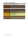
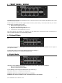
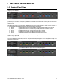
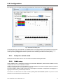
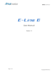
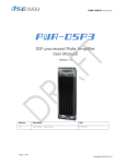
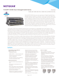
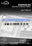
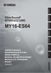
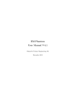
AuviTran Audio ToolBox AxC-SW D5 G Instructions M anual Switch Interface Card for Audio ToolBox Platform AxC-SWD5G User’s Manual V1.1 Ver sion 1 .0 1 WARNING Always follow the basic precautions listed below to avoid the possibility of serious injury or even death from electrical shock, short-circuiting, damages, fire or other hazards. These precautions include, but are not limited to, the following: PRECAUTIONS Do not apply excessive pressure on connectors or any other part of the board. Do not touch the metallic sharp parts (pins) of the product. This product is electrostatic sensitive; make sure you check this before touching or using it. The disconnect devices of the Audio ToolBox unit are the appliance inlet of the auxiliary power supply and the appliance inlet on the rear side of the unit. These must be easily reachable. AxC-SWD5G User’s Manual V1.1 To prevent electric shock, unplug the unit before handling. The achievement of other operations not mentioned in this document is prohibited. Repairs can be performed only by a technician trained and qualified. Each connection must be Safety Extra Low Voltage kind (SELV), and must stay inside buildings. 2 LIMITATION OF LIABILITY In no case and in no way, the provider of this Product (AuviTran, the distributor or reseller, or any other party acting as provider) shall be liable and sued to court for damage, either direct or indirect, caused by and to the user of the board and which would result from an improper installation or misuse of the Product. “Misuse” and “improper installation” mean installation and use not corresponding to the instructions of this manual. Please note that graphics given in this manual (drawings and schemes) are only examples and shall not be taken for a real vision of your own equipment configuration. AuviTran is constantly working on the improvement of the products. For that purpose, the products functionalities are bound to change and be upgraded without notice. Please read carefully the User’s manual as the new functionalities will be described therein. TRADEMARKS All trademarks listed in this manual are the exclusive property of their respective owners. They are respected “as is” by AuviTran. Any use of these trademarks must receive prior approval of their respective owners. For any question, please contact the trademark’s owner directly. COPYRIGHT The information in this manual is protected by copyright. Therefore, reproduction, distribution of whole or part of this manual is strictly forbidden without the prior written agreement of AuviTran. Our product use open source software MSTPd and LWIP respectively under GNU Lesser Public License and BSD license. With respect to the free/open source software listed in this document, if you have any questions or wish to receive a copy of the source code to which you are entitled under the applicable free/open source license(s) please contact us at: http://www.auvitran.com/w2/index.php/contact/contact-form?sendto=info&title=General%20Information. Full licences and open sources project home addresses are available at the end of this document. AUVITRAN WEBSITE / MORE INFORMATION Please visit our website for any question of further inquiry concerning our product range. Updates will also be posted when available. http://www.auvitran.com PACKAGE CONTAINS 1 AxC-SWD5G card + Thumbscrews AxC-SWD5G User’s Manual V1.1 3 TABLE OF CONTENTS PRECAUTIONS ............................................................................................................... 2 LIMITATION OF LIABILITY............................................................................................. 3 TRADEMARKS ............................................................................................................... 3 COPYRIGHT.................................................................................................................... 3 AUVITRAN WEBSITE / MORE INFORMATION .............................................................. 3 PACKAGE CONTAINS ................................................................................................... 3 1 WELCOME! .......................................................................................................... 5 2 OVERVIEW........................................................................................................... 5 3 TECHNICAL SPECIFICATIONS........................................................................... 6 4 FRONT PANEL / WIRING .................................................................................... 7 4.1 LINKED MODE ..................................................................................................... 7 4.2 SPLIT MODE ........................................................................................................ 7 5 AXC-SWD5G ON AVS-MONITOR........................................................................ 8 5.1 CONTROL PANEL VIEW ..................................................................................... 8 5.2 CONFIGURATION ................................................................................................ 9 5.2.1 SETUP THE SWITCH MODE ............................................................................... 9 5.2.2 VLAN SETUP ....................................................................................................... 9 5.2.3 SPANNING TREE............................................................................................... 10 6 NETWORK ARCHITECTURES .......................................................................... 13 7 FREQUENTLY ASKED QUESTIONS ................................................................ 16 8 OPEN SOURCE LICENSES ............................................................................... 16 AxC-SWD5G User’s Manual V1.1 4 1 WELCOME! Thank you for purchasing AuviTran’s Audio Toolbox AxC-SWD5G extension card. We hope you will enjoy using it. You will find here the necessary instructions to use your product. Please read them carefully as misuse of this device might cause serious damage to you and your environment. 2 OVERVIEW As all AxC cards within the AuviTran range, the AxC-SWD5G can equally be used in AVBx3 or AVBx7 ToolBox. Using one slot only, it provides 8 x RJ45 Gigabit Ethernet Port, plus 2 x SFP (Small Form-Factor Pluggable) cages for direct optical fiber connection via optional monomode or multimode SFP also called mini-GBIC (Gigabit Interface Converter) modules. Bring optical fiber into your network without additional external switch or media converter! The AxC-SWD5G card has two configurations: - One unified Ethernet switch featuring 10 Gigabit ports, or - Two physically independent full speed Ethernet switches, each of them offering 5 Gigabit ports for split redundancy network. Thanks to AVS-Monitor, the AxC-SWD5G can be fully and remotely managed, using either: IP, Dante or EtherSound networks. AVS-Monitor will also provide statistics on any port, an easy way to dynamically check and analyse, in real time, the capability of the links. VLAN can be configured on any port to use multi-protocol (DANTE, ES100, COBRANET, DMX/Ethernet…) over a same optical fiber at same time on the AxC-SWD5G. Use the user friendly spanning tree between two AxC-SWD5G switches to prevent a link failure in your loop. AxC-SWD5G User’s Manual V1.1 5 3 TECHNICAL SPECIFICATIONS AxC–Switch: Switch card for the AuviTran Audio ToolBox platform General Size Power Supply Storage: Temp / Humidity Operating: Temp / Humidity Connectors 200 mm x 100 mm x 40 mm – Format AuviTran Audio ToolBox platform cards +12V / +3.3V - Through AuviTran Audio ToolBox backplane - 5°C to 70°C / 0% to 95% (non-condensing) 0°C to 40°C / 5% to 90% (non-condensing) 8 x RJ45 connectors, 2x SFP/GBIC connectors Switch and CPU Specifications Processor Dedicated Switch memory Port Speed Auto MDIX VLAN capability Spanning tree capability Performances Audio Video Bridging (AVB) Capability Dual Core ARM processor @ 204 MHz, 192KB SRAM, 4MB flash, 8MB SDRAM 2 x 128KB Packet Buffer size with a data bus of 256 bits wide Auto Neg. or forced at 1Gigabit/s, 100 Mbit/s, 10 Mbit/s Full /Half duplex mode Automatically adjusts for straight-through or crossover cables on all RJ45 ports Up to 32 independent configurable 802.1Q VLAN STP, RSTP 802.1W-2001, and MSTP 802.1Q-2005 1000 MB latency < 2.9 μs (64-byte packets) 100 Mb Latency < 4.9 μs (64-byte packets) MAC address table size of 2 x 8192 entries AVB Ready _ Supports 802.1 Audio Video Bridging (AVB) Standards - 802.1AS – Precise Timing Protocols - 802.1Qat – Stream Reservation Protocol - 802.1Qav – Egress Pacing and Jitter Tolerance Integration Environment Audio ToolBox platform AVS-ESMonitor Supported OS AxC-SWD5G can be inserted in any slot of any AuviTran Audio ToolBox platform AVS-Monitor enables to remotely set, control and monitor a Dante or an EtherSound network and provides enhanced control pages to manage the AxC-SWD5G card specific parameters Windows 8/7/Vista/XP for 32 or 64 bit versions AxC-SWD5G User’s Manual V1.1 6 4 FRONT PANEL / WIRING Fig1: AxC-SWD5G front panel AxC-SWD5G card provides 8x RJ45 Giga-Ethernet ports and 2x SFP (Small Form-Factor Pluggable) Giga-Ethernet ports to allow various architecture possibilities. The SFP cages, also called mini-GBIC (Gigabit Interface Converter) modules allow you to add optical fiber into your network. Those modules are available in many formats: Multimode Fiber Gigabit SFP transceiver Monomode Fiber Gigabit SFP transceiver Single Fiber Bi-Directional Gigabit SFP Transceiver Copper/Ethernet Cabling Gigabit SFP transceiver Few modes, with their own restrictions, are available on your AxC-SWD5G device. Please read carefully the following lines to avoid any mistakes and network errors when building a network. 4.1 Linked Mode When powered up for the first time, your AxC-SWD5G card will start in “linked” mode. In this mode, all 10 ports are switched together and behave the same way. You can see your AxC-SWD5G card as a regular 10 ports Giga-Ethernet switch. The green LED “Linked” on the front panel indicates that this mode is active (fig 1). Please refer to the section 5.2.1 to configure the following modes. 4.2 Split Mode In this setup your AxC-SWD5G card will behave as two distinct 5 ports switches, with the following distribution: - port 1 to 5 for the first 5 ports switch - port 6 to 10 for the second 5 ports switch. The red LED “Split” on the front panel indicates that this mode is active (fig 1). Please refer to section 5.2.1 to configure the following modes. WARNING: In Split mode the spanning tree options is not available. WARNING: In this mode it is forbidden to cable a link between the two “split” switches. AxC-SWD5G User’s Manual V1.1 7 5 AXC-SWD5G ON AVS-MONITOR 5.1 Control Panel View Your SWD5G card is fully functional for the AVS-Monitor version 4.0.14 or further. This software allows you to monitor and configure your new hardware. Fig 2: AVS-Monitor Control Panel The above Fig 2, is an example of a running AxC-SWD5G as it will appear on the AVS-Monitor “Control” panel. For each port, this panel allows you to monitor the auto-negotiate speed and the attributed VLANs. Please refer to the chapter 5.2.2 to learn how to configure a VLAN. Next to SFP ports number 5 and 10 the mention “N/A” appears to show that in this configuration, no SFP device is connected. On the contrary, AVS-Monitor will display the type of module and link mode as describe below: AxP-BD* Single fiber bidirectional down monomode SFP (mini-GBIC) transceiver with half LC connector AxP-BU* Single fiber bidirectional up monomode SFP (mini-GBIC) transceiver with half LC connector AxP-SX Double fiber multimode SFP (mini-GBIC) transceiver with LC connector AxP-LX Double fiber monomode SFP (mini-GBIC) transceiver with LC connector AxP-RJ Copper/Ethernet cabling SFP (mini-GBIC) transceiver with RJ45 connector Note*: AxP-BD and AxP-BU must be coupled as they use different wave lengths for bidirectional transmission/reception to work together in a single optical fiber. This panel in indicates the switch mode (“Linked” or “Split”) and the Spanning tree algorithm you are using (Refer to chapter 5.2.3 to know how to use the STP). Fig 3: SWD5G AVS-Monitor display in Split mode with spanning tree off Fig4: SWD5G AVS-Monitor display in Linked mode with RSTP spanning tree set AxC-SWD5G User’s Manual V1.1 8 5.2 Configuration By a single click on your front panel device picture of the AVS-Monitor “Control” panel, the “Slot Setup” panel will popup. Fig 5: AVS-Monitor Slot Setup panel On this Setup panel (Fig 5), all the features of your SWD5G switch can be configured intuitively. All modifications on this panel will be applied by the “Save & Close” button. If you do not wish to save your modifications, simply close the popup window or click “cancel”. By selecting and apply “Recall Default” all parameters of the “Slot Setup” panel will be set as factory setting. 5.2.1 Setup the switch mode These options are described in section 4.1 and 4.2 to select a mode, set the matching radius button. 5.2.2 VLAN setup VLAN on SWD5G cards are implemented accordingly to the normalisation IEEE 802.1Q, which allows this hardware to be fully compatible with others commercial IEEE 802.Q switches. VLANs are used to create Virtual Local Area Networks on a unique architecture. This allows for example to split the sound and the commands on different routes, or even data flows on multiple links. The frame is tagged to identify a VLAN, and each ports of each bridges on the network are configured to route (tagging or untagging) the frame in the way to create multiple virtual LAN. The VLAN ID 1 is the default VLAN. This VLAN is mandatory even if you do not use VLANs capabilities. If a port has no VLAN attributed, it will be automatically link to the default VLAN. AxC-SWD5G User’s Manual V1.1 9 Click on the “ADD” line on the table to set a new VLAN. Then fill an ID number from 2 to 4096 and select a colour (for an easier check-up of your setup). By validating the “SET” button, you will see your new VLAN appear in the VLAN table (Fig 3), where the relation between ports and VLAN is made. In this table the lines represents VLANs and columns the ports. The default VLAN has the ID 1 and a black colour. It cannot be deleted, all ports are by default untag member of this VLAN. After adding a VLAN in the table, you can modify the relation between a port and your VLAN by left clicking in the port column of your choice. Ingress/egress rule can be added on these ports in the table below with “Interport Switch” (Fig 3). Between two VLAN capable switches, use the “Interport Switch” option to exchange multiple VLAN packets on the same link. On the opposite Untag VLAN will be used to send untag frame to end point devices which do not accept VLAN. In advanced mode: If you are in the “advanced” setup “Force Untag” will be also available. The setup mode allows you to “Tag” none “Interport Switch” port’s VLAN. Ingress/egress rules: U (Untag): Accept (ingress), untagged and tagged, frame of this ID then distribute (egress) them untagged. Untag rule is mainly used when a port is connected to a terminal device, such as an AxC-ES100 EtherSound Card, frames will be untagged before reaching the device. T (Tag): Accept tagged frame of this ID then distribute them tagged. This option is be used on bridge interlinks; each frame will keep their tags, so the switch will be able to distribute them on the relevant ports. Force Untag: Distribute all frame untagged (override T distribute rule). Interport Switch: Ignore untagged frame. To avoid untagged frame on a bridge interlink. Delete a VLAN by clicking its line and on its ID column, then clicking the delete button (Fig 3). Please refer to the section 6 to find some network architectures examples. 5.2.3 Spanning tree The spanning tree algorithm in AxC-SWD5G is compliant with its description in the documentations: IEEE 802.1W-2001 for the STP/RSTP and 802.1Q-2005 for the MSTP. The spanning tree allows you to create loops between bridges without causing any redundancy traffic and creating a backup route in case of a link failure. STP is the first normalisation, and because of the very long recovery time on a link change ( >30 seconds), it is strongly recommended to use the RSTP or the MSTP versions of the spanning tree. This very simple example below will help you to understand the utility of a spanning tree. RSTP Bridge 1 RSTP Bridge 2 RSTP Bridge 3 Fig 6: A simple loop network with RSTP In the example Fig 6, the three AxC-SWD5G switches are fully configured to use RSTP algorithm. Bridge 2 has been chosen as the master switch in the spanning tree. This means that every bridge will try to find a path to reach him. To avoid producing a loop on the network, the spanning tree on bridge 1 closes the port on the link between bridge 1 and 3. AxC-SWD5G User’s Manual V1.1 10 Link lost! RSTP Bridge 1 RSTP Bridge 2 RSTP Bridge 3 Fig 7: A simple loop network with RSTP As shown in Fig 7, if a link failure appears on the link between Bridge 1 and 2, bridge 1 will open its port on the link with bridge 3 in order to communicate with bridge 2. As a result, the network is still fully operational. For compatibility with regular switch auto negotiation, a link change will take approximately 750ms. Fig 8: AVS-Monitor Slot Setup panel (MSTP) To use the spanning tree ability, simply set “Rapid Spanning Tree Mode” on. Then each “lnterport Switch” port will be RSTP active. To work correctly inter port switches must be connected to a compatible RSTP device. AxC-SWD5G User’s Manual V1.1 11 In advanced mode: To configure an STP/RSTP/MSTP on your AxC-SWD5G device, simply set the “Spanning Tree Mode” on the desired algorithm: - STP: First version of spanning tree. It must be used only in case of backward computability with old switch. It involve a slow detection of disconnection/reconnection with up to 10s cut of transmission. - RSTP: Rapid Spanning Tree. It provides a quick management of redundant link connection / disconnection with a delay of a second (In a simple case). - MSTP: Multiple Spanning Tree Protocol. It provides capabilities to manage different STP for each VLAN enabling to select a better path of links between switches for different VLAN. Fig 8 shows that when spanning tree mode is selected, the “BPDU filter” line appears in the bottom of the second table. Set the filter “X” to inhibit any spanning tree activity on the selected port. This will disable the transmission of spanning tree management frames that may disturb a device that cannot manage them (cf EtherSound devices for examples). Set ”X the inter-switch connections that use the select STP mode. These are the only STP/RSTP parameters. To finalise a MSTP configuration, check that all STP_ID (column STP), fit your configuration. STP_ID can take a value from 1 to 63. Two or more VLANs can be attributed to the same STP_ID. A MSTP bridge linked with a RSTP one will automatically use RSTP algorithm. All MSTP bridges on a network must have the same STP_ID attributed to the same VLAN ID. Normalisations use many others parameters, they will be accessible upon request: contact AuviTran teams (Available soon). Please refer to the section 6 to find some network architectures examples using RSTP or MSTP. AxC-SWD5G User’s Manual V1.1 12 6 Network architectures The audio ToolBox by AuviTran allows you to exchange your audio data between a various set of protocols. The possibilities are huge, but in order to help you to wisely setup your perfect sound network, this chapter contains few examples of the use of AuviTran hardware. Dante Single Loop Fig 9 shows a Dante network built over four AxC-SWD5G. Thanks to the RSTP, if one fiber link is cut, the network remains fully operational. From the control room, the control link is used to configure all the hardware. Dante and control frames are dispatched through the fiber links. VLAN features of the SWD5G will be useful in this situation. By tagging the control and Dante frames on a different VLAN, the switches will be able to route those two types of frames separately. In the rack cabinet the AxC-SWD5G switch is also used to connect other hardware to the network without adding any switch. To secure the voltage transformer of the AxC-SWD5G and the whole ToolBox, an auxiliary power supply is also available, ask our sales team! Control link AuviTran auxiliary power supply MIXER (Digico, Protools, Soundcraft, …) SP SP Bridge Dante DX8O Amps AES-ES SP … Bridge Dante Madi Control room Fiber loop using RSTP algorithm Bridge Dante DX8I in a Rack Bridge Dante AX4O Digital input Analog output RACK Rack cabinet Fig 9: A Dante single loop AxC-SWD5G User’s Manual V1.1 13 192ch over Ethernet Soundcraft mixer 64ch Digico mixer 64ch M7CL48-ES mixer 64ch 3 4 2 192ch over Dante In a RSTP loop 2,3,4 2 4 3 Fig 10: 192 channels over Dante The above Fig 10 shows the schematic of a 192ch over Dante network between two ToolBoxes. As shown above (Fig. 7 and 8) a RSTP loop is pictured. This time VLANs are used to route all three 64 channels from one AxC-DANTE to the other. Numbers on links identify VLANS. Default VLAN 1 can be used for control frames. The 192 channels will use about 600MB of our 1GB throughout. AxC-SWD5G User’s Manual V1.1 14 7 6 8 7 Amps Matrix Stage unit 1 Control room Fiber loop using RSTP algorithm 4 8 2 3 5 Amps 4 3 Stage unit 2 2 Matrix CONTROL VLAN Matrix BI-DIRECTIONAL ETHERSOUND Matrix Rack cabinet INTER SWITCH LINK Fig 11: Bi-directional EtherSound network Fig 11 shows an EtherSound network where VLANs can be used to create a virtual loop. To build an EtherSound daisy-chain, the frames will be routed from OUT ports into IN ports. . The scheme pictures green links for Ethersound, the figures are the VLAN Ids and orange cable is the Control VLAN. This setup gives you a smart example of double security in case of links failure: First you can rely on the natural EtherSound capability to detect a link failure and to reorganize a new dasy-chain adapt to the new conditions. Second, the rapid spanning tree which also resists in case a link is lost, thus providing maximal security in your network. AxC-SWD5G User’s Manual V1.1 15 7 FREQUENTLY ASKED QUESTIONS How do I control the AxC-SWD5G switch? The AxC-SWD5G can be added in any slot of your ToolBox. Control of your hardware will be made through AVS-Monitor and the connection of an AxC-ES100 or AxC-DANTE to your work station. This feature will be soon available from your AxC-SWD5G directly How many AxC-SWD5G can I add in my ToolBox? You may fill every slot with AxC-SW5G if your network configurations requires so, but don’t forget that you should save one slot for an AxC-ES100 or an AxC-DANTE, which will give you access to your Toolbox on AVS-Monitor. How can I reset my AxC-SWD5G to the factory settings? In the panel “Control” of the AVS-Monitor the button “RACK SETUP” gives you access to the “Revert to Factory settings” option. I linked a fiber network, but it’s doesn’t seems to work. What could I do? Fiber links are not automatically crossed/uncrossed. Please check that every optical-fiber is correctly crossed between two switches. Also keep in mind that AxP-BD and AxP-BU must be coupled as they use different wave lengths for bidirectional transmission/reception to work together in a single optical fiber. Once these adjustments achieved, if your system is still nonoperational, please contact AuviTran team. Why do I get some trouble to connect my Dante network with commercial switches? The Green Ethernet capability of your switches must be deactivated to be fully compatible with the Dante protocol. We look forward to and value our customers’ feedback ! Please share your most inventive network configurations! 8 OPEN SOURCE LICENSES LWIP This includes un-modified version of LWIP v1.4.1 The original files can be downloaded at: http://savannah.nongnu.org/projects/lwip Copyright (c) 2001-2004: Swedish Institute of Computer Science. All rights reserved. MSTPd The original files can be downloaded at: http://sourceforge.net/projects/mstpd/ AxC-SWD5G User’s Manual V1.1 16