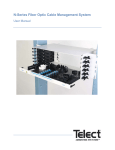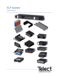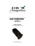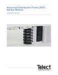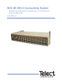
1
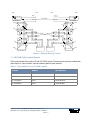
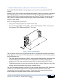
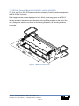
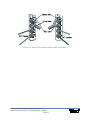
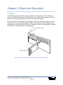
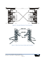
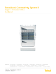
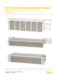
BCS 4R DSX-3 Connectivity System
Models 010-8332-0410, 010-8332-0401, 010-8324-0410
and 010-8324-0401
User Manual
BCS 4R DSX-3 Connectivity System
Models 010-8332-0410, 010-8332-0401, 010-8324-0410
and 010-8324-0401
User Manual, Part number 139256
Copyright 2010, Telect, Inc., All Rights Reserved
Telect and Connecting the Future are registered trademarks of Telect, Inc.
1730 N Madson St., Liberty Lake, Washington
Telect assumes no liability from the application or use of these products. Neither does Telect convey any
license under its patent rights nor the patent rights of others. This document and the products described
herein are subject to change without notice.
About Telect
Telect offers complete solutions for physical layer connectivity, power, equipment housing and other
network infrastructure equipment. From outside plant and central office to inside the home, Telect draws on
more than 25 years of experience to deliver leading edge product and service solutions. Telect is
committed to providing superior customer service and is capable of meeting the dynamic demands of
customer and industry requirements. This commitment to customer and industry excellence has positioned
Telect as a leading connectivity and power solution provider for the global communications industry.
Technical Support
E-mail: [email protected]
Phone: 888-821-4856 or 509-921-6161
Telect, Inc. • USA +1.509.926.6000 • Mexico +52.33.3836.37.52
www.telect.com • © 2010 Telect, Inc., All Rights Reserved, 139256 A0
Page ii
BCS 4R DSX-3 Connectivity System
User Manual
Table of Contents
Chapter 1: BCS 4R DSX-3 ......................................................................................................... 1
1.1 Introduction to Telect’s BCS 4R ....................................................................................... 1
1.1.1 BCS 4R Fully-Loaded Chassis ................................................................................ 3
1.1.2 BCS 4R DSX-3 Module (Models 010-8301-0401 & 010-8302-0401) ...................... 4
1.1.3 BCS 4R Chassis (Model 010-0000-8301 and 010-0000-8302) .............................. 5
1.1.4 Applications ............................................................................................................. 6
1.1.5 Cutover / Acceptance Activities ............................................................................... 6
1.1.6 Restoration of Service Activities.............................................................................. 6
1.1.7 Routine Maintenance Activities ............................................................................... 6
1.1.8 Features / Capabilities / Capacities / Benefits ......................................................... 7
1.1.9 Compliance ............................................................................................................. 7
1.2 DSX-3 Specifications ........................................................................................................ 8
Chapter 2: Installation ............................................................................................................... 9
2.1 Installation Considerations ............................................................................................... 9
2.1.1 Location and Space ................................................................................................ 9
2.1.2 Computer Floor Issues .......................................................................................... 10
2.1.3 Required Tools and Equipment.............................................................................. 10
2.2 Inspection ....................................................................................................................... 10
2.3 Installation ...................................................................................................................... 11
Chapter 3: Electrical Operation .............................................................................................. 17
3.1 Power ............................................................................................................................. 17
3.1.1 Tracer Lamps (TL) ................................................................................................ 18
3.1.2 Monitor Ports ......................................................................................................... 18
3.2 DSX Cross-Connections ................................................................................................ 18
3.2.1 Backplane Cross-Connections .............................................................................. 18
3.2.2 DSX Card Front Patch .......................................................................................... 20
Chapter 4: Service ................................................................................................................... 21
4.1 Owner Maintenance ....................................................................................................... 21
4.2 Troubleshooting Cross-Connected Signals ................................................................... 21
4.3 Replacing the Tracer Lamp LED .................................................................................... 21
4.4 Service ........................................................................................................................... 21
4.4.1 In-Warranty Service .............................................................................................. 21
4.4.2 Out-Of-Warranty Service........................................................................................ 22
4.5 Repacking For Shipment ............................................................................................... 22
Telect, Inc. • USA +1.509.926.6000 • Mexico +52.33.3836.37.52
www.telect.com • © 2010 Telect, Inc., All Rights Reserved, 139256 A0
Page iii
List of Figures
Figure 1 - Basic Chassis .............................................................................................................. 1
Figure 2 - Rear View of Fully Loaded Chassis ............................................................................. 2
Figure 3 - Network Element Circuits ............................................................................................ 3
Figure 4 - Cross-connect Inputs................................................................................................... 4
Figure 5 - Model 010-0000-8301 ................................................................................................. 5
Figure 6 - Rack ............................................................................................................................ 9
Figure 7 - Mounting Chassis to Rack ......................................................................................... 11
Figure 8 - Routing Power ........................................................................................................... 12
Figure 9 - Grounding the Chassis .............................................................................................. 13
Figure 10 - BNC Insertion Tool .................................................................................................. 13
Figure 11 - Connections ............................................................................................................. 14
Figure 12 - Rear Cross-Connect Cables with Tracer Wire ........................................................ 15
Figure 13 - Power from Distribution Panel to Front Tracer Lamp .............................................. 17
Figure 14 - Tracer Lamp Operation ........................................................................................... 18
Figure 15 - Schematic Drawing of Cross-Connection................................................................ 19
Figure 16 - Rear Cross-Connect Cables with Tracer Wire ........................................................ 19
Figure 17 - Temporary Front Cross-Connect Using Patch Cables & DSX Cards ...................... 20
Telect, Inc. • USA +1.509.926.6000 • Mexico +52.33.3836.37.52
www.telect.com • © 2010 Telect, Inc., All Rights Reserved, 139256 A0
Page iv
Chapter 1: BCS 4R DSX-3
1.1 Introduction to Telect’s BCS 4R
Telect’s BCS 4R is a low-cost, high-density, space-saving total solution to DSX-3 network
element connectivity.
Telect’s 2 RU BCS 4R chassis accommodates up to 32 of Telect’s highly reliable, 6-port BCS 4R
DSX-3 modules. Each low-cost DSX-3 module features BNC and Mini-WECO connectors for
cross-connecting, patching, testing. and bi-directional monitoring of network element circuits.
Panels are available fully configured and loaded with DSX-3 modules, helping to simplify
purchasing and installation. Options include 24-termination/19" and 32-termination/23" panels,
with 6-port DSX-3 modules. All panels are just 4" in height.
Front
Rear
Figure 1 - Basic Chassis
Telect, Inc. • USA +1.509.926.6000 • Mexico +52.33.3836.37.52
www.telect.com • © 2010 Telect, Inc., All Rights Reserved, 139256 A0
Page 1-1
BCS 4R
BCS 4R
Figure 2 - Rear View of Fully Loaded Chassis
Telect, Inc. • USA +1.509.926.6000 • Mexico +52.33.3836.37.52
www.telect.com • © 2010 Telect, Inc., All Rights Reserved, 139256 A0
Page 1-2
FRONT
REAR
REAR
BATT A
TL
BATT A
TL
TL
TL
TRACER WIRE
RTN A
LED ASSEMBLY
FRONT
RTN A
LED ASSEMBLY
MON
MON
R2
R2
OUT
OUT
R1
OX
OX
IX
IX
R1
R1
R1
IN
O
O
I
I
R2
I
O
O
Network Element 1
MON
IN
R2
I
Network Element 2
MON
Figure 3 - Network Element Circuits
1.1.1 BCS 4R Fully-Loaded Chassis
Telect now provides fully-loaded 19” and 23” DSX-3 panels. These products come pre-loaded with
either 6-port or 4-port modules. See the following table for part numbers.
Table 1 - Fully-loaded 19” and 23” DSX-3 panels
Chassis
Module
Part Number
19”, 24-position
6-port
010-8324-0410
19”, 24-position
4-port
010-8324-0401
23”, 32-position
6-port
010-8332-0410
23”, 32-position
4-port
010-8332-0401
Telect, Inc. • USA +1.509.926.6000 • Mexico +52.33.3836.37.52
www.telect.com • © 2010 Telect, Inc., All Rights Reserved, 139256 A0
Page 1-3
1.1.2 BCS 4R DSX-3 Module (Models 010-8301-0401 & 010-8302-0401)
Telect’s BCS 4R DSX-3 Module is a 4-port passive card module for populating the BCS 4R
Chassis.
Model 010-8301-0401 fits every odd-numbered shelf position (Positions 1 through 31) and Model
010-8302-0401 fits every even position (Positions 2 through 32). (BCS 4R DSX-3 Module kit
[Model 999-8300-0401] contains one odd and one even module.) The BNC connections on the
rear of the even versus the odd modules are slightly offset to accommodate 32, side-by-side
modules in each chassis.
BNC circuit assignments are as follows:
•
Input (I) to and Output (O) from the network element, and
•
Cross-connect input (XI) and output (XO) — from/to another DSX-3 module. Cross-connections between DSX-3 Modules should be 27 ft. or less.
Figure 4 - Cross-connect Inputs
The four ports on the front of the module are Mini-WECO connectors for temporary Input (I) and
Output (O) patch cords (734A or 735A cables) from/to a standby DSX-3 circuit, and for temporary
Monitor (M) patch cords:
•
The I and O patch connections are intrusive, highly reliable, make-and-break connections that
break (disconnect) the cross-connect circuits at the same time making (connecting) the
standby circuit. Patch cord connections between DSX-3 modules should be 20 ft. or less.
•
The M connections are non-intrusive connections that allow for testing, diagnosis, and troubleshooting without disconnecting either normal or standby service.
The front of the module contains a red tracer LED fed by power supplied from a GMT power shelf.
A tracer wire is inserted through the rear of the BCS 4R Chassis; the tracer lamp is lit by
grounding the tracer wire at the trace controller. Tracer lamps aid in diagnosing problems by
visually mapping out assigned network element cross connections.
Telect, Inc. • USA +1.509.926.6000 • Mexico +52.33.3836.37.52
www.telect.com • © 2010 Telect, Inc., All Rights Reserved, 139256 A0
Page 1-4
1.1.3 BCS 4R Chassis (Model 010-0000-8301 and 010-0000-8302)
The 23-in. and 19-in. BCS 4R Chassis are shelves containing 32 and 24 positions, respectively,
for BCS 4R DSX-3 modules.
Each chassis includes a power backplane to feed -48Vdc, tracer-lamp power to the DSX-3
modules. Each chassis comes with cable management ring assemblies that attach to the rear of
the rack and flipout designation cards that attach to the mounting brackets on the front of the
rack. (Designation cards are not shown in the following illustration.) All mounting hardware
is included.
Figure 5 - Model 010-0000-8301
Telect, Inc. • USA +1.509.926.6000 • Mexico +52.33.3836.37.52
www.telect.com • © 2010 Telect, Inc., All Rights Reserved, 139256 A0
Page 1-5
1.1.4 Applications
Telect’s BCS 4R System is ideal for central offices and other DSX-3 distributive activities
including
•
high-density central offices
•
other DS3 network applications
•
cutover / acceptance activities
•
restoration of service activities
•
routing maintenance activities
as well as normal DCS interconnects, or wherever reliable, low-cost DSX-3 connectivity is
a must.
1.1.5 Cutover / Acceptance Activities
BCS 4R DSX-3 simplifies equipment installation and cutover by providing temporary digital line
patch cord connections during new equipment installation. After the new equipment has been
wired to the DSX, cross-connections are made to connect the new equipment in its final office
configuration. Removing the wiring from the DSX to the old equipment and taking down the patch
cords completes the cutover.
1.1.6 Restoration of Service Activities
Malfunctioning equipment is readily identified at the BCS 4R DSX-3 by equipment
sectionalization (circuit split-test in both directions) and by patching substitute equipment for
verification. Digital line patch cords at the DSX can immediately restore any out-of-service facility,
whether caused by a cable cut, malfunctioning equipment, etc. Rather than using jacks located at
the individual units, manual restoration patching can be done at a centralized location — at the
DSX. When the equipment or cable is repaired or routing for preventive maintenance is
accomplished, the facility can be returned to its original configuration by simply removing the
patch cords.
1.1.7 Routine Maintenance Activities
Periodic testing of facility parameters assures maintenance of adequate service levels. By
terminating all digital office equipment at one central point — at the BCS 4R DSX-3 — overall
testing can be performed from the central location. Periodic testing at DSX test jacks, connected
directly to digital equipment inputs and outputs, identifies marginal equipment.
Circuit order work is another important routine maintenance activity. Major changes in traffic
patterns may leave a surplus of capacity at a vacated area and a shortage at another. Traffic
pattern changes are rapidly accomplished by reconfiguring cross-connect jumpers at the DSX.
The ability to make these changes at the DSX makes major rewiring unnecessary and results in
a reduction of skilled manpower and time requirements.
Telect, Inc. • USA +1.509.926.6000 • Mexico +52.33.3836.37.52
www.telect.com • © 2010 Telect, Inc., All Rights Reserved, 139256 A0
Page 1-6
1.1.8 Features / Capabilities / Capacities / Benefits
Telect’s BCS 4R offers the following:
•
total front access for patching and monitoring
•
easy access to cross-connections
•
75Ω impedance
•
support for all coaxial interface digital signal rates (DS3, STS-1, E-3, STM-1, and STS-3)
•
network I/O and Cross-Connect BNCs on the rear; patch and high-impedance Monitor MiniWECO on the front
•
bi-directional monitoring
•
tracer lamps for identifying cross-connections during troubleshooting
•
fully configured panels that streamline ordering and accelerate deployment
•
high density: 24 terminations in a 19" chassis; 32 terminations in a 23" chassis
•
space savings: Each panel just 4" in height
•
essential functionality: 6-port mini-WECO modules enable bi-directional monitoring, patch,
test and cross-connect capabilities; 4-port modules also available
•
simplified design: LEDs on front only; cable equipment to panel as you add modules
•
NEBS Certified and backed by Telect's DSX lifetime warranty
1.1.9 Compliance
•
NEBs Level 3
•
cULus
•
FCC
•
CE
Telect, Inc. • USA +1.509.926.6000 • Mexico +52.33.3836.37.52
www.telect.com • © 2010 Telect, Inc., All Rights Reserved, 139256 A0
Page 1-7
1.2 DSX-3 Specifications
Electrical Interface:
Specifications:
Insertion Loss
< 1.00 dB at DS3/E3 signal rates
Monitor Level
21 dB + 1.5 dB below signal level
Return Loss
< -26 dB at DS3/E3, STS-1 signal rates
< -26 dB at E3 signal rate of 17.184 Mhz
< -15 dB at STS-3/STM-1 signal rates
Contact Resistance
< 0.01Ω
Characteristic Impedance
75Ω
Tracer Lamp LED
Draws 9mA at -48Vdc
Mechanical Interface:
Specifications:
Jack Insertion Force
10 lbs maximum, 4.1 lbs. minimum
Jack Withdrawal Force
7 lbs. maximum, 3.8 lbs. minimum
Jack Life
Minimum 10,000 insertion/withdrawal cycles
Environment:
Specifications:
Thermal Ambient Limits
-55°C to 85°C, non-operating
-5°C to +55°C, operating
Thermal Shock
per MIL-STD-202, methods 107D
Humidity
0% to 95%, noncondensing, operating and non-operating
Telect, Inc. • USA +1.509.926.6000 • Mexico +52.33.3836.37.52
www.telect.com • © 2010 Telect, Inc., All Rights Reserved, 139256 A0
Page 1-8
Chapter 2: Installation
2.1 Installation Considerations
!
CAUTION
CAUTION! Only qualified technicians may install and maintain his product.
These instructions presume you have verified that the Telect equipment being installed is
compatible with the rest of the system, including power, ground, circuit protection, signal
characteristics, equipment from other vendors, and local codes or ordinances.
!
ALERT
Use this equipment in a RESTRICTED ACCESS LOCATION ONLY.
2.1.1 Location and Space
The BCS 4R chassis mount in standard 19 in. or 23 in. WECO-spaced or EIA-spaced racks.
Allow for four inches of vertical space per chassis.
BCS
4
R
Figure 6 - Rack
Telect, Inc. • USA +1.509.926.6000 • Mexico +52.33.3836.37.52
www.telect.com • © 2010 Telect, Inc., All Rights Reserved, 139256 A0
Page 2-9
2.1.2 Computer Floor Issues
The weight of a fully populated BCS 4R bay may exceed 500 lbs. Each configuration will vary in
weight depending on number and type of cards and cables used. Adding repeaters will increase
weight. If bay weight exceeds the support capacity of your floor, computer floor supports may be
required.
2.1.3 Required Tools and Equipment
•
BNC crimpers for constructing BNC connector ends. Die sets required, depending on cable.
•
BNC insertion tool, Telect PN 097197.
2.2 Inspection
Compare the contents of the shipping container with the packing list. Call Telect or your
distributor if you are missing anything.
Telect is not liable for shipping damage.
If the shipping container is damaged, keep it for the carrier’s inspection. Notify the carrier and call
Telect’s Customer Service Department: 1-800-551-4567 or 1-509-926-6000
Keep the container until you have checked equipment operation. If you experience any kind of
problem, call Telect’s Customer Service Department. Use the original, undamaged container if
you are instructed to return the BCS 4R component to Telect.
Telect, Inc. • USA +1.509.926.6000 • Mexico +52.33.3836.37.52
www.telect.com • © 2010 Telect, Inc., All Rights Reserved, 139256 A0
Page 2-10
2.3 Installation
1. Mount the BCS 4R chassis, along with designation cards, to a rack, using the four supplied
mounting screws (two per side). Torque to 35 in.-lbs (4.29 N•m.).
Figure 7 - Mounting Chassis to Rack
2. Install cable management rings on the rear rack flange using the hardware provided.
3. Repeat Steps 1 and 2 to install all BCS 4R chassis before installing power and I/O cables to
any BCS 4R chassis in the rack.
4. For BCS 4R chassis that require power, route power from the power distribution panel to connectors on the rear of BCS 4R chassis.
Use wire in the 10-22 AWG range. Strip away about 3/8 in. (~10 mm) of insulation and then
press in on the tab at the top of the connector to open the connector’s jaws. Insert the wire
below the tab and then release the tab to cinch the wire.
Telect, Inc. • USA +1.509.926.6000 • Mexico +52.33.3836.37.52
www.telect.com • © 2010 Telect, Inc., All Rights Reserved, 139256 A0
Page 2-11
Figure 8 - Routing Power
Telect, Inc. • USA +1.509.926.6000 • Mexico +52.33.3836.37.52
www.telect.com • © 2010 Telect, Inc., All Rights Reserved, 139256 A0
Page 2-12
5. Ground the chassis lug to the rack using #6- to #14-AWG stranded wire and a single-hole
compression ring lug for a #8 stud.
Figure 9 - Grounding the Chassis
6. Connect I/O cables to the rear of the chassis, as shown in the following illustration.
In general,
•
For network I/O cables originating overhead, start with the lowest BCS 4R chassis in the
rack and work up.
•
For network I/O cables originating from below, start with the highest chassis in the rack
and work down.
•
NE I/O cables connect to the lower I/O connectors on the chassis. Use a BNC
insertion tool.
Figure 10 - BNC Insertion Tool
Telect, Inc. • USA +1.509.926.6000 • Mexico +52.33.3836.37.52
www.telect.com • © 2010 Telect, Inc., All Rights Reserved, 139256 A0
Page 2-13
7. Use cable ties liberally along the lower tie-down bar and tie-down lances (loops) at the rear of
the chassis.
8. Insert cross-connecting cables to upper two connectors, labeled IX and OX on DSX cards.
9. If applicable, connect tracer wire to the port above the tracer LED, as shown.
10. Use cable ties along the upper tie-down bar to restrain the X-connect cables.
Figure 11 - Connections
Telect, Inc. • USA +1.509.926.6000 • Mexico +52.33.3836.37.52
www.telect.com • © 2010 Telect, Inc., All Rights Reserved, 139256 A0
Page 2-14
Figure 12 - Rear Cross-Connect Cables with Tracer Wire
Telect, Inc. • USA +1.509.926.6000 • Mexico +52.33.3836.37.52
www.telect.com • © 2010 Telect, Inc., All Rights Reserved, 139256 A0
Page 2-15
This page intentionally left blank.
Telect, Inc. • USA +1.509.926.6000 • Mexico +52.33.3836.37.52
www.telect.com • © 2010 Telect, Inc., All Rights Reserved, 139256 A0
Page 2-16
Chapter 3: Electrical Operation
3.1 Power
The BCS 4R equipment is passive with the exception of the repeater and Vector OTM card
modules. The DSX chassis accept -48V office battery power to light the tracer lamps (TL) LED on
the front of DSX and repeater cards and LEDs on the rear of the chassis.
Power connects to the Power/Alarm Terminal Strip on the back of each DSX chassis. The strip
terminates a bus on the chassis backplane; all DSX card connectors on the backplane tap into
the signal lines of this bus. Power for the rear TLs passes from the bus on the backplane, through
the DSX card, to a small PCB also on the backplane.
Power from Distribution Panel
Tracer Lamp
Figure 13 - Power from Distribution Panel to Front Tracer Lamp
Telect, Inc. • USA +1.509.926.6000 • Mexico +52.33.3836.37.52
www.telect.com • © 2010 Telect, Inc., All Rights Reserved, 139256 A0
Page 3-17
3.1.1 Tracer Lamps (TL)
The TL lights up when a plug is inserted into one of the monitor jacks on the front of a DSX card.
Also, with the monitor plug in place, TLs of cross-connected cards will flash for 30 seconds, then
light steadily.
Rtn A
Power from
Backplane
Batt A
MON
OX
Tracer Wire Jack
TL
Backplane Tracer Lamp
O
I
IX
MON
Figure 14 - Tracer Lamp Operation
3.1.2 Monitor Ports
All DSX cards have at least one monitor port on the front side, labeled “M” or “MON”. Test
equipment may be applied without interrupting service. The three-port card has a monitor for the
OUT signal only.
3.2 DSX Cross-Connections
Do not make rear cross-connections using cables longer than 27 ft, unless using a repeater card.
Do not make front patch connections longer than 20 feet.
3.2.1 Backplane Cross-Connections
To cross-connect two network elements, use approved coax cable and connect the OX (X-OUT)
port from the card for network element 1 (NE-1) to the IX (X-IN) for network element 2 (NE-2),
AND connect the OX port for NE-2 to the IX port from NE-1. See the diagrams below.
Telect, Inc. • USA +1.509.926.6000 • Mexico +52.33.3836.37.52
www.telect.com • © 2010 Telect, Inc., All Rights Reserved, 139256 A0
Page 3-18
BATT A
TL
BATT A
TRACER WIRE
TL
RTN A
LED ASSEMBLY
MON
R2
O
X
TL
TL
RTN A
R1=75
R2=768
R1=75
R2=768
LED ASSEMBLY
O
X
X-OUT
X-OUT
R1
R1
O
O
O
O
I
I
I
I
Network
Element 1
R1
Network
Element 2
R1
I
X
FRONT
X
I
X-IN
X-IN
MON
MON
R2
R2
R2
REAR
REAR
Figure 15 - Schematic Drawing of Cross-Connection
Figure 16 - Rear Cross-Connect Cables with Tracer Wire
Telect, Inc. • USA +1.509.926.6000 • Mexico +52.33.3836.37.52
www.telect.com • © 2010 Telect, Inc., All Rights Reserved, 139256 A0
Page 3-19
MON
FRONT
3.2.2 DSX Card Front Patch
Install front patches to temporarily re-route signals. Patches with jacks labeled O,OX, I, IX are
intrusive and interrupt service. Use 734A or 735A cable. Patch only to cards less than 20 feet
away. Remove temporary patches in accordance with office procedures after permanent
backplane cross-connections have been made.
Figure 17 - Temporary Front Cross-Connect Using Patch Cables & DSX Cards
Telect, Inc. • USA +1.509.926.6000 • Mexico +52.33.3836.37.52
www.telect.com • © 2010 Telect, Inc., All Rights Reserved, 139256 A0
Page 3-20
Chapter 4: Service
4.1 Owner Maintenance
Telect’s BCS 4R components do not need preventive maintenance. The only service you can
perform is to replace these assemblies if they fail:
•
DSX Card Module
•
Repeater Card Module
•
DNI Card Module
•
Chassis
•
Tracer lamp LEDs, on card and on backplane
4.2 Troubleshooting Cross-Connected Signals
Check for correct and firm cable connections at the termination and cross-connect points on
every card.
4.3 Replacing the Tracer Lamp LED
Pull the LED assembly and plastic holder straight out.
If LED polarization is not correct, the replacement will not work. Orient the new LED in the plastic
holder the same as the original. The shape of the LED holder slot in the DSX module is keyed for
proper LED insertion.
4.4 Service
4.4.1 In-Warranty Service
Contact your Telect equipment distributor, or call a Telect Customer Service Representative:
1-800-551-4567
1-509-926-6000
Telect will repair or replace defective products within the limits of the warranty. See “Repacking
for Shipment” in this section.
Call a Customer Service Representative for a Return Material Authorization (RMA) before
returning any equipment.
Telect, Inc. • USA +1.509.926.6000 • Mexico +52.33.3836.37.52
www.telect.com • © 2010 Telect, Inc., All Rights Reserved, 139256 A0
Page 4-21
4.4.2 Out-Of-Warranty Service
The procedure for out-of-warranty service is the same as for in-warranty service, except that
Telect charges a processing fee, and you must submit a Purchase Order along with a Return
Material Authorization (RMA) before returning equipment. Call a Customer Service
Representative for help getting these forms.
The processing fee guarantees a repair estimate and is credited against actual material and
labor costs.
4.5 Repacking For Shipment
Telect is not liable for shipping damage.
1. Tag the equipment showing owner’s name, address, and telephone number, together with a
detailed description of the problem.
2. Use the original shipping container if possible. If you do not have it, package the equipment in
a way to prevent shipping damage. Include the RMA inside the container.
3. Insure the package.
Telect, Inc. • USA +1.509.926.6000 • Mexico +52.33.3836.37.52
www.telect.com • © 2010 Telect, Inc., All Rights Reserved, 139256 A0
Page 4-22