1
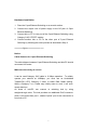
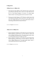
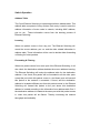
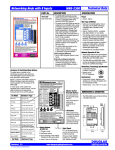
User’s Manual
for
5-Port 10/100Mbps Nway
Auto-Negotiation Switching Hub
(Revision 1.0)
Edition 1.0 (Aug 1997)
FCC Class A Appliance
This equipment has been tested and found to comply with the limits for a Class A
digital device, pursuant to Part 15 of the FCC Rules. These limits are designed to
provide reasonable protection against harmful interference when the equipment
is operated in residential installation. This equipment generated, uses, and can
radiate radio frequency energy and if not installed and used in accordance with
the instruction manual may cause harmful interference to radio communications.
However, there is no guarantee that interference will not occur in a particular
installation. If this equipment does cause harmful interference to radio or
television reception, which can be determined by turning the equipment off and
on, the user is encouraged to try to correct the interference by one or more of the
following measures:
Reorient or relocate the receiving antenna.
Increase the separation between the equipment and receiver.
Connect the equipment into an outlet on a circuit different from that to
which the receiver is connected.
Consult the dealer or an experienced radio TV technician for help.
NOTICE:
1.The changes or modifications not expressly approved by the party responsible
for compliance could void the user’s authority to operate the equipment.
2.Shielded interface cables and AC power cord, must be used in order to comply
with emission limits.
3.If the device is changed or modified without permission from company, the user
may void his or her authority to operate the equipment.
Contents is subject to revision without prior notice. All rights reserved.
All other trademarks belong to their respective owners.
CE Mark Declaration of Conformance
This is to certify that this product complies with ISO/IECGuide 22 and EN45014.
It conforms to the following specifications:
This product complies with the requirements of the Low Voltage Directive
73/23/EEC and the EMC Directive 89/336/EEC.
1
Checklist
Check the contents of your package for following parts:
5-port Ethernet Switching
Power Supply and Accessory
User’s Manual
If any of these pieces are missing or damaged, please contact your dealer
immediately, if possible, retain the carton including the original packing
material, and use them against to repack the product in case there is a
need to return it to us for repair.
2
Contents
Introduction
Features and Specifications
Hardware Description
Front Panel
Rear Panel
Hardware Installation
Configuration
10/100 Mbps (Server) Switching
10/100 Mbps (Hub) Switching
Switch Operation
Address Table
Learning
Forwarding & Filtering
Store-and-Forward
Troubleshooting
Introduction
3
The 5-port Ethernet Switching is designed to allow simultaneous
transmission of multiple packets via an internal high-speed data channel.
This means that it can partition a network more efficiently than bridges or
routers in most environments. This 5-port Ethernet Switching is a highly
reliable network switch and is the ideal device for bridging Ethernet to
Fast Ethernet workgroups or networks. Simple and cost-effective, the
5-port Ethernet Switching supports IEEE802.3u, IEEE802.3, 100Base-TX,
10Base-T and 100Base-FX. The 5-port Ethernet Switching is therefore
fast being recognized as one of the most important building blocks for
today networking technology.
Compact in size and designed for Plug and Play installation, the 5-port
Ethernet Switching allows the network administrator to simply connect the
network and power cables and the switching/bridging functions begin
automatically. No hardware or software configurations are required.
The front panel of the 5-port Ethernet Switching provides LEDs for easy
recognition of the switch operation status and for troubleshooting. These
LEDs display the power status for the system and link, speed, full-duplex,
and receive status for each port.
With 5–port Ethernet Switching designed specifically for connecting
workgroup devices and desktops, companies no loger have to invest in
expensive and inflexible switches engineered primarily for backbone
implementations. Instead, companies can deploy scaleable, affordable
switches that increase the aggregate bandwidth of the network by
boosting throughput to the workgroups that need it most.
4
Features and Specifications
l
5-port 10/100Mbps TX Auto-Negotiation Ethernet Switching Hub
l
Complies with the IEEE802.3 Ethernet and IEEE802.3u Fast Ethernet standard
l
Features Store-and-Forward, Cut-Through, and Safe-Cut-Through architectures
with wire-speed filtering and forwarding rates
l
Full/Half-Duplex capability on every TX ports, total bandwidth is up to
200Mbps/port
l
Automatic MAC address learning and aging
l
Runt and CRC Filtering eliminates erroneous packets to optimize the network
bandwidth
l
Provide external power supply
l
LED indicators for simple diagnostics and management
l
Optional manual control switch for 10M/100M Full-Duplex, the default switch
positions are set on Auto-Negotiation mode
l
Provide an extra port for MDI and MDI-X mode changing
l
Plug and Play
Specifications:
l
Standard: IEEE802.3/IEEE802.3u
l
Network Media:
100Base-TX – UTP/STP category 5 cable
10Base-T – UTP/STP category 3 or 5 cable
l
Connector: STP RJ-45 port for 10/100Mbps TX
l
LED indicators:
System – Power OK LED.
Individual port – Link, Receiving activity, Speed, and Full duplex/collision LEDs
l
Dimension: 220mm(L) x 130mm(W) x 27mm(H)
l
Temperature: Operating – 0? to 50?
l
Humidity: Operating – 10% to 90% RH
l
Input Power Requirement: 5VDC, 3A max. regulated power supply
l
Registrations: FCC Part 15 Class A, CE
5
Storage – -20? to 70?
Storage – 5% to 90% RH
Hardware Description
This section describes the hardware features of the 5-port Ethernet
Switching. For easier management and control of the switch, familiarize
yourself with its display indicators, and ports. Front panel illustrations in
this chapter display the unit LED indicators. Before connecting any
network device to the hub, read this chapter carefully.
Front Panel
The unit front panel provides a simple interface monitoring the switching
hub. It includes a power indicator for each port.
======Figure of front panel====
LED indicators
LED Function
Power (PWR)
Color
Green
Link
Green
10/100
Green
FDX/COL
Yellow
RX
Green
Description
Lit: Power On
Unlit: Power Off
Lit: Indicates the adapter is
connect to the hub
Lit: Indicates the speed is 100
Mbps (Default)
Unlit: Indicates the speed is 10
Mbps
Lit: Full duplex operation
Flashing: Collision
Indicates incoming traffic entering
the port
Rear Panel
The rear panel of the 5-port Ethernet Switching hub indicates a DC-jack
power socket, which accepts exactly DC 5V power from the adapter.
=====figure of rear panel========
6
Hardware Installation
1. Place the 5-port Ethernet Switching on a smooth surface
2. Connect the output cord of power supply to the DC-jack of 5-port
Ethernet Switching.
3. Connect hub or PC to one port of the 5-port Ethernet Switching using
Category 3/4/5 UTP/STP cabling.
4. Connect another hub or PC to the other port of 5-port Ethernet
Switching by following the same process as described in Step 3.
========figure ==============
Notice:
Cable distance for 5-port Ethernet Switching
The cable distance between 5-port Ethernet Switching and hub/PC should
not exceed 100 meter.
Make sure the wiring is correct
It can be used Category 3/4/5 cable in 10 Mbps operation. To reliably
operate your network at 100Mbps, you must use an Unshielded
Twisted-Pair (UTP) Category 5 cable, or better Data Grade cabling.
While a Category 3 or 4 cable may initially seem to work, it will soon
cause data loss.
All kinds of hub/PC can connect to switching hub by using
straight-through wires. The hub provides one additional RJ45 connector
which is converted from port 1, labeled “Uplink” port for the connection is
from hub or PC.
7
Configuration
100Mbps Server to 10Mbps Hub
1.
Plug one end of the Category 5 UTP Cable into any one port of the
5-port Ethernet Switching, and the other end of this cable into the
RJ-45 of Fast Ethernet Adapter in the server. The cable length
between these 2 connecting points should not exceed 100 meter.
2.
Plug one end of the Category 3 UTP Cable into “Uplink” port of the
5-port Ethernet Switching, and the other end of this cable into any
port of the 10Mbps Ethernet hub. The cable length between these 2
connecting points should not exceed 100 meter.
========Figure==========
10Mbps Hub to 100Mbps Hub
1.
Plug one end of the Category 5 UTP Cable into one port of the 5-port
Ethernet Switching, and the other end of this cable into “Uplink” port
of the 100Mbps Fast Ethernet Hub. The cable length between these
2 connecting points should not exceed 100 meter.
2.
Plug one end of the Category 3 UTP Cable into one port of the 5-port
Ethernet Switching, and the other end of this cable into “Uplink” port
of the 10Mbps Ethernet Hub. The cable length between these 2
connecting points should not exceed 100 meter.
=======figure===========
8
Switch Operation
Address Table
The 5-port Ethernet Switching is implemented with an address table. This
address table composed of many entries. Each entry is used to store the
address information of some node in network, including MAC address,
port no, etc.
These information comes from the learning process of
Ethernet Switching.
Learning
When one packet comes in from any port. The Ethernet Switching will
record the source address, port no. and the other related information in
address table. These information will be used to decide either forwarding
or filtering for future packets.
Forwarding & Filtering
When one packet comes from some port of the Ethernet Switching, it will
also check the destination address besides the source address learning.
The Ethernet Switching will lookup the address table for the destination
address. If not found, this packet will be forwarded to all the other ports
except the port which this packet comes in. And these ports will transmit
this packet to the network it connected. If found, and the destination
address is located at different port from this packet comes in, the Ethernet
Switching will forward this packet to the port where this destination
address is located according to the information from address table. But, if
the destination address is located at the same port with this packet comes
in, when this packet will be filtered. Thereby increasing the network
throughput and availablity
9
Store-and-Forward
Store-and-Forward is one type of packet-forwarding techniques.
A
Store-and Forward Ethernet Switching stores the incoming frame in an
internal buffer, do the complete error checking before transmission.
Therefore, no error packets occurrence, it is the best choice when a
network needs efficiency and stability.
The 5-port Ethernet Switching scans the destination address from the
packet header, searches the routing table provided for the incoming port
and forwards the packet, only if required. The fast forwarding makes the
switch attractive for connecting srvers directly to the network, thereby
increasing throughput and availability. However, the switch is most
commonly used to segment existing hubs, which nearly always improves
overal performance. A Ethernet Switching can be easily cofigured in any
Ethernet network environment to significantly boost bandwidth using
conventional cabling and adapters.
Due to the learning function of the Ethernet switching, the source address
and corresponding port number of each incoming and outgoing packet
are stored in a routing table. This information is subsequently used to filter
packets whose destination address is on the same segment as the source
address. This confines network traffic to its respective domain, reducing
the overall load on the network.
The 5-port Ethernet Switching performs “Store and forward” therefore, no
error packets occur. More reliably, it reduces the re-transmission rate.
No packet loss will occur.
10
Troubleshooting
This chapter contains information to help you solve problems.
If the
5-port Ethernet Switching is not functioning properly, make sure the 5-port
Ethernet Switching was set up according to instructions in this manual.
1.
The Link LED is not Lit
Solution:
a.
Make sure the switch configuration is consistent with the
connecting device
b.
2.
Check the cable connections.
Performance is bad
Solution:
a.
Check the full duplex status of the Ethernet Switching. If the
Ethernet Switching is set to full duplex and the partner is set to
half duplex, then the performance will be poor.
3.
Some stations can not talk to other stations located on the other
port
Solution:
a.
The address table may contain older information than of the
address table of that node. Please power down to refresh the
address information.
11