1
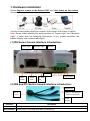
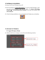
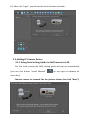
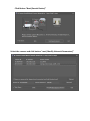
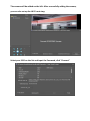
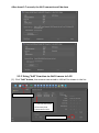
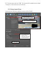
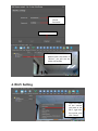
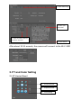
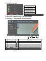
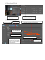
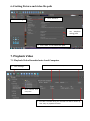
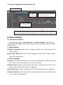
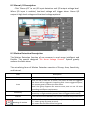
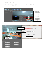
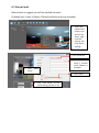
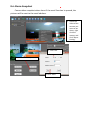
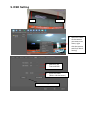
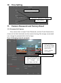
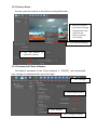
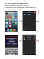
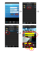
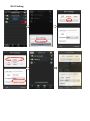
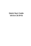
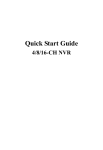
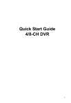
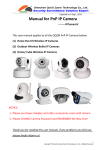
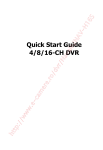
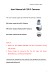
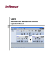
Updated on 6 August, 2014 Manual for PnP IP Camera --------IPCameraV This user manual applies to all the PnP IP Cameras below: Home Pan-tilt IP Cameras Outdoor Waterproof IP Cameras Fixed Dome IP Cameras NOTICE: 1. Please use the POWER ADAPTER and other accessories coming with camera! 2. Please change the password after the first login, and please REMEMBER your CHANGED PASSWORD! Thank you for reading this user manual, if any problems you find out, please kindly inform us! Table of Content 1. Hardware Installation ......................................................................................... 3 2. Software Installation .......................................................................................... 3 3. Access to Camera .............................................................................................. 4 3.1 Login IP Camera Client ....................................................................................................................... 4 3.2 Adding IP Camera Device .................................................................................................................. 5 3.2.1 Using Auto Setting Guide to Add Camera in LAN ........................................................................... 5 3.2.2 Using “Add” Function to Add Camera in LAN ................................................................................. 8 3.2.3 Using Context Menu ....................................................................................................................... 9 4. Wi-Fi Setting ..................................................................................................... 10 5. PT and Color Setting ......................................................................................... 11 5.1 PT Control Panel .............................................................................................................................. 11 5.2 Color Control Panel.......................................................................................................................... 12 6. Record, Snapshot and Two way Audio ........................................................... 12 6.1 Operation of alarm, snapshot and two way audio .......................................................................... 12 6.2 Record onto SD Card........................................................................................................................ 13 6.3 Schedule Record .............................................................................................................................. 13 6.4 Setting Picture and video file path .................................................................................................. 14 7. Playback Video ................................................................................................. 14 7.1 Playback Video Recorded onto Local Computer.............................................................................. 14 7.2 Remote Playback Video from SD Card ............................................................................................. 15 8. Alarm Setting .................................................................................................... 15 8.1 Alarm Introduction .......................................................................................................................... 15 8.2 Alarm I/O Description...................................................................................................................... 16 8.3 Motion Detection Description ......................................................................................................... 16 8.4 Alarm Record ................................................................................................................................... 18 8.5 Alarm Email ..................................................................................................................................... 19 8.6 Alarm Snapshot ............................................................................................................................... 20 9. OSD Setting ...................................................................................................... 21 10. Time Setting ...................................................................................................... 22 11. Camera Password and Factory Reset ............................................................ 22 11.1 Password of Camera ...................................................................................................................... 22 11.2 Factory Reset ................................................................................................................................. 23 11.3 Password of Client Software.......................................................................................................... 23 12. Visit Camera over Smart Phone ...................................................................... 24 1. Hardware Installation Please Connect camera to the Router FIRST and then Power on the camera , like the following way: Use the correct power supply for camera, and connect it to router or switch. Note: Please check whether the working status of “Power Light” and “Network Light” is same with the following description, if not, please reconnect the power adaptor and network cable again. (1) IPA Series Camera Interface Introduction: Power Light Network Light Antenna I/O Port Audio Output RJ 45 Port Power Supply SD Card Slot (2) IPB and IPC Series Camera Interface Introduction: RS485 Port RJ 45 Audio In, connected to Port external microphone Power Supply Definition Description Power Indicator Orange color, it is always on when device is powered and network cable is connected correctly Data Indicator Green color, it is blinking when data is transmitting 2. Software Installation (1) Insert the CD into CD driver of your PC (2) Click the button of “Install CMS Software” to run the install package; or you can open the CD directly, find out the folder “1. Camera Monitoring Software2. PC Monitoring Client Software” and install the software” IPC CMS Software”. (3) After finishing installation, the icon like below will display on your desktop 3. Access to Camera 3.1 Login IP Camera Client (1) Double click the icon to login in; you will see the following interface (2) After click “Login”, you will see the client interface as below: 3.2 Adding IP Camera Device 3.2.1 Using Auto Setting Guide to Add Camera in LAN The first time running the CMS, setting guide will pop up automatically (you can click button “Install Wizzard” on top right of software on menu bar); Connect camera to network like the pictures below (Just click “Next”): Click Button “Next (Search Device)” Select the camera and click button “next (Modify Network Parameters)” The camera will be added on the left. After successfully adding the camera, you can also set up the Wi-Fi next step; Select your SSID on the list and input the Password, click “Connect” After about 5-7 seconds, the Wi-Fi connection will be done 3.2.2 Using “Add” Function to Add Camera in LAN (1). Click “Add” button, the cameras connected to LAN will be shown in the list: 1. Click “Add“Button 2. Tick the Check box of Cameras that Connected in LAN 3. Click to Add Camera (2). Tick the camera and click “Add”. The camera will be added into the folder “Cameras” on the camera list on the left side; 3.2.3 Using Context Menu You can use this function to add the cameras in LAN or WLAN 1. Right Click folder “Device” 2. Click “Add Device through ID” 3. Fill in a name of the camera and any information you want to describe camera 4. Click “Next” 5. Fill in Device ID and Password 6. Click “Finished” 7. Double click the camera added under the folder of “Device”, you will see the video successfully 4. Wi-Fi Setting 1. Select the video of the camera you want to set Wi-Fi, right click the mouse, and click “Setup” 2. Click “Wi-Fi” tag 4. Select your Wi-Fi SSID 5. Input the WIFI password and click “Connect” 3. Click “search” After about 10-15 seconds, the camera will connect to the Wi-Fi SSID 5. PT and Color Setting 5.1 PT Control Panel 1. PT Control Arrow 3. PT Speed Control 2. Cruise Setting 5.2 Color Control Panel 6. Brightness Adjustment 5. Saturation Adjustment 4. Contrast Adjustment 3. Saturation Adjustment 2. Image Mirror Setting 1. Wide Dynamic Range Setting (FOR WDR Camera) 6. Record, Snapshot and Two way Audio 6.1 Operation of alarm, snapshot and two way audio ① ② No. Function 1 2 3 4 5 6 7 Record Folder Original Size/Tile Snapshot Alarm Listen-in Talk Back Record Icon ② ③ ④ ⑤ ⑥ ⑦ Description Click to open the video file that recorded on the computer Show the original size of the video Click to capture the current camera image When alarm triggered, the “Alarm” button will turn RED. Click “Listen-in” button to hear sound around the camera. Collect voice around you and transmit to the camera side Record the video manually 6.2 Record onto SD Card 1. Right click the screen and select “setup” 2. Select the “Record” tag, to setup SD Card record Parameters 6.3 Schedule Record 1. Click “Manage” 4. Select Camera 5. Set the schedule of recording, red square means the camera will record video at this selected time 2. Click “Record Manage” 3. Click “Schedule Record” 6. Click “Save” to save the schedule 8. Click “Setting” to set record duration of time, for example, when set 20, every video file will be 20 minutes 7. Click “Change” to set video saving path 6.4 Setting Picture and video file path 2. Click “General” 1. Click “Mange” 3. Click “Save” to set snapshot saving path 4. Click “Save” to set video save path 7. Playback Video 7.1 Playback Video Recorded onto Local Computer 2. Set start time and end time, and then click “Search” 1. Click “Manage” 1. Click “Record onto Computer” 4. The video recorded during the selected time will be shown up, click “Play” to playback the video 7.2 Remote Playback Video from SD Card 1. Click “Manage” 3. Select Camera 4. Set start time and end time, then click “Search” 2. Click “ Record onto SD Card” 5. The video recorded during the selected time will be shown up, click “Download”, after the video is downloaded completely, and click “Play” to playback the video 8. Alarm Setting 8.1 Alarm Introduction Alarm Setting includes “Alarm Source” and “Alarm Strategy”. Alarm Source means what will trigger alarm. Alarm Linkage means how the camera will notify the alarm to us 1. Alarm Source: (1) Motion Detection: Alarm will be triggered when the camera detects the motion object. (2) I/O Input Detection: Alarm will be triggered when the I/O Input detects low-level voltage signal. 2. Alarm Linkage: (1) Alarm: When Motion Detection or I/O input is detected, the CMS will sound the siren as well as pop up the alarm events windows. (2) Alarm Email: Camera sends email (including snapshot and event) to the preset email address when alarm is triggered. (3) Alarm Record: Camera records video onto SD Card when alarm is triggered. (4) Alarm Snapshot: When the switch is opened, the alarm pictures will be send to the specific email address 8.2 Alarm I/O Description Click “Alarm I/O” to set I/O input detection and I/O output voltage level. When I/O input is enabled, low-level voltage will trigger alarm. Alarm I/O output is high-level voltage and low-level voltage optional. 2 3 4 1 8.3 Motion Detection Description The Motion Detection function of our cameras is much more intelligent and flexible. The special designed “Six Areas Linkage Control” System greatly reduces the false alarm. The actualizing form of Motion Detection consists of Group, Area, Sensitivity, and Interval. Item Description Group User can set SIX groups alarms at most User can set 6 areas for an alarm, only when 6 areas all triggered, the alarm will be triggered. Comparing with 1 area triggered system, this system greatly reduces the false alarm. Note: One group supports Six areas at most; user can set 1-6 areas according to different requirement. The sensitivity of motion detection, the larger value is, the higher sensitivity is. High sensitivity means alarm is triggered more easily. Area Sensitivity Interval Meaning of number The interval of time between the current area and the previous area The first “1” means the number of area (6 areas at most), the second “1” means group (6 groups at most). 1-1 means the first area of the first group Application 1: One area trigger: For example: When the bag is moved, the alarm is triggered. 2. Tick “Group 1” 3. Tick “Area 1” 1. Click “on” Of the switch 4. Classify “Area 1” into” Group 1” 5. Set sensitivity 6. Click “Save” Application 2: Several areas trigger: For example: Only when a person is getting in door, the alarm is triggered. If only a dog (or some other little animal) is getting in the door, the alarm will be not triggered, as the dog can’t trigger THREE areas at the same time. (This system greatly reduces false alarm) 2. Tick “Group 1” 3. Tick “Area 1” Area 3 Area2 Area 1 4. Tick “Area 2” & “Area 3” 1. Click “on” Of switch 5. Classify “Area 1” & “Area 2” & “Area 3” into Group 1 6. Set sensitivity 7. Click “Save” 8.4 Alarm Record When alarm is triggered, the camera will record video onto SD Card 1. Select the video of the camera you want to set alarm, right click the mouse, and click “Alarm Setting” 1. 3. Select “On” 4. Fill in recording time 2. Click “Alarm record” 5. Click “Save” 8.5 Alarm Email When alarm is trigged, you will be notified via email (Outlook mail, Gmail, 163mail, 126mail and Sohu mail are available) 1. Select the video of the camera you want to set alarm, right click the mouse, and click “Alarm Setting” 2. 3. Turn on Switch 2. Click “Alarm Email” 4. Fill in receiver email, 5 receiver email address is available 5. Click “Save” 6. Click “Test email” to test email setting success or not 8.6 Alarm Snapshot Camera takes snapshot when alarm if the email function is opened, the pictures will be sent to the email address. dsafdsaf 1. Select the video of the camera you want to set alarm, right click the mouse, and click “Alarm Setting” 3. Click “On” 2. Click “Alarm Snapshot” 4. Click “Save” 9. OSD Setting OSD TimeOSD 1. Select the video of the camera you want to set alarm, right click the mouse, and click “Alarm Setting” 2. Switch on the Time and OSD 3. Input the Letter (Within 18 characters) 4. Click “Setting” and “OK” 10. Time Setting 1. Select “Time Setting”” 2. Tick “NTP”, ”Manual” or “From PC” 3. Click “Setting” 11. Camera Password and Factory Reset 11.1 Password of Camera Every camera has a unique ID and Password, and the ID and Password are shown on the label attached onto the camera housing. We strongly recommend user change the password after the first login. Steps of changing camera’s password: 1. Select the camera you want to change the password, then right click the mouse, and then click “Setup” 2. Click “Advance Setting” 3. Fill in “New Password” & “Confirm Password” and click “Change”, then click “Apply” and “OK” 11.2 Factory Reset You can reset the camera to the factory setting like below 1. Select the camera you want to change the password, then right click the mouse, and then click “Setup” 2. Click “Advance Setting” 3. Click “Res Default” to reboot the camera 11.3 Password of Client Software The default password of the client software is “123456”, we recommend user change the password after your first login 1. Click “Manage” 3. Input New Password 2. Click “Change” 4. Click “Change Password” 12. Visit Camera over Smart Phone IOS System: Download “Oview” from “App Store” Android System: input “play.google.com” into web browser and search “Oview” or copy from CD. Click Click video, you will see Four arrows, click the arrow to move the monitoring area Listen in Talk back Snapshot Record Video Wi-Fi Setting