1
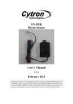
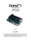
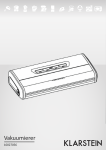
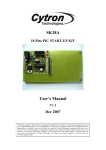
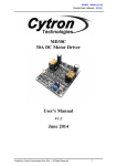
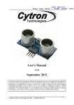
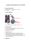
RE08A
Rotary Encoder Kit
User’s Manual
V1.2
September 2008
Information contained in this publication regarding device applications and the like is intended through suggestion only and may
be superseded by updates. It is your responsibility to ensure that your application meets with your specifications. No
representation or warranty is given and no liability is assumed by Cytron Technologies Incorporated with respect to the accuracy
or use of such information, or infringement of patents or other intellectual property rights arising from such use or otherwise. Use
of Cytron Technologies’s products as critical components in life support systems is not authorized except with express written
approval by Cytron Technologies. No licenses are conveyed, implicitly or otherwise, under any intellectual property rights.
1
Index
1. Introduction and Overview
3
2. Packaging List
4
3. Product Specification
5
4. Board Layout
6
5. Installation (hardware)
7
6. Getting Started
9
7. Warranty
10
2
1. INTRODUCTION AND OVERVIEW
RE08A is a rotary encoder kit which comes with a slotted disc (8 slots) and a simple interface
sensor board. No further soldering is required. Rotary encoder is a sensor or transducer used
to convert the data of rotary motion into a series of electrical pulses which is readable by
controller. The slotted disc has a 35mm outside diameter with 8 slots that provides 16
transitions. The optical sensor is used to sense the 16 transitions of the slotted disc. With
these transitions, controller is able to recognize the rotary angle of the disc. With this concept,
a rotary encoder can be employed in a DC motor shaft for the controller to ‘know’ its current
position.
This rotary encoder kit has been design with the features of:
• Industrial grade PCB with high reliability yet professional outlook.
• Every component is soldered properly and every kit is tested before being shipped
to customer.
• Simple 3 pin interface (+5, Gnd and Sig).
• Included On board green LED as indicator.
• Direct connection to microcontroller (internal pull-up to 5V).
• Up to 1 KHz (1000 pulse/sec).
• Disc size: 35mm (outer diameter) x 3mm(inner diameter)
• Sensor board size: 12mm (height) x 35mm (length) x 15mm (width)
This document explains the method to use RE08A.
3
2. PAKAGING LIST
Please check the parts and components according to the packing list. If there are any parts
missing, please contact us at [email protected] immediately.
Sensor board
8 slots disc
1. 1 x RE08A sensor board
2. 1 x 8 slots disc
4
3. PRODUCT SPECIFICATION
Electrical Characteristics
Symbol
Parameter
+5
Sensor board supply voltage
Gnd
System Ground
Sig
Signal output
Vlow
Voltage during low stage (+5 = 5V)
Vhigh
Voltage during high stage (+5 = 5V)
f
Output frequency
Ion
Current at low state
Ioff
Current at high state
TOPR
Operating Temperature
Min
4.5
0
0
4.5
0
25
5
0
Typ
5
0.8
4.7
30
10
25
Max
5.5
5.3
1.0
4.9
1
40
20
75
Unit
V
V
V
V
V
KHz
mA
uA
°C
Truth Table in Normal Operating Condition (+5 = 5V)
Optical
Signal
LED status
sensor
Comment
ON
Unblocked
0V
Low state at “Sig” output pin
OFF
Blocked
5V
High state at “Sig” output pin
* Blocked = The center space blocked by the slotted disc.
5
4. BOARD OR PRODUCT LAYOUT
B
C
A
D
E
Label
Function
Optical Sensor
A
+5 input supply
B
Ground/Negative of supply
C
Label
Function
Signal output/pulse output
D
Indicator LED
E
Optical sensor at “A” will detect the missing slot of disc when the disc rotate, further
generate pulses at signal pin.
Header pin at “B” is input supply. User should connect 5V (+) to this pin.
Header pin at “C” is ground of 5V supply, or in other words, the negative terminal of supply.
Header pin at “D” is signal output of sensor board. This pin is internally pull-up to 5V, thus
no extra component is needed for this sensor to be connected to controller.
LED at “E” is an indicator. This LED will light ON if the disc does not block the optical
sensor.
6
5. INSTALLATION (HARDWARE)
The hardware installation is divided into two parts. The first part is sensor board. Following
figure shows example of wiring from sensor board to a microcontroller.
5V
Microcontroller
GND
Counter
Pulses
generated
5V
Time
Simply connect the “+5” and “Gnd” to 5V supply, further connect the “Sig” pin to
microcontroller input pin. Normally, the “Sig” will be connected to Counter/Clock/Encoder
input for automatic counting purpose.
Note: Please DONOT connect wrong polarity input to sensor board. This will ruin
the sensor.
Second portion of hardware installation is the slotted disc. This disc should be mounted to
motor shaft or gear output as shown in following figure.
Motor
Gear
Head
Shaft
Slotted
Disc
7
To get the rotation output from rotating shaft, the slotted disc must be placed within the space
between optical sensor as shown in the following picture.
Output
shaft
Slotted
Disc
Optical
Sensor
Note: Please DONOT break the slot of slotted disc during installation.
8
6. GETTING STARTED
After installation, the rotary encoder is ready to count the rotation of output shaft. This
information can further be calculation to obtain speed of output shaft or the velocity of motor.
This kit is very simple and compact, connect to any microcontroller via the 3-pin header. The
onboard infrared beam detects missing slots in a slotted encoder disk, and generates a pulse
train. The generated pulses are a 0 to 5V output. It provide a +5V output when the optical
beam is blocked, and a 0V output when the beam is unblocked. The microcontroller can
simply read the 0-5-0V pulse train to determine the distance of robot if the shaft is mounted
to wheel and the wheel diameter is known, of course it can further be used for velocity.
Simply follow the installation guide and configure microcontroller to count the pulses
generated when the shaft rotates. Software configuration is not covered in this document as
there are too many type of microcontroller and each of them have different configuration.
Please refer to related data sheet of each microcontroller for the configuration details.
9
7. WARRANTY
¾
¾
¾
¾
Product warranty is valid for 6 months.
Warranty only applies to manufacturing defect.
Damage caused by mis-use is not covered under warranty.
Warranty does not cover freight cost for both ways.
Prepared by
Cytron Technologies Sdn. Bhd.
19, Jalan Kebudayaan 1A,
Taman Universiti,
81300 Skudai,
Johor, Malaysia.
Tel:
Fax:
+607-521 3178
+607-521 1861
URL: www.cytron.com.my
Email: [email protected]
[email protected]
10