1
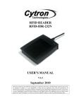
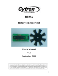
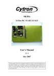
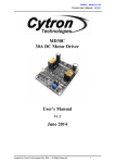
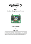
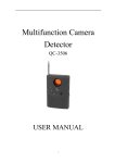
SN-SHK Shock Sensor User’s Manual V1.2 February 2011 Information contained in this publication regarding device applications and the like is intended through suggestion only and may be superseded by updates. It is your responsibility to ensure that your application meets with your specifications. No representation or warranty is given and no liability is assumed by Cytron Technologies Incorporated with respect to the accuracy or use of such information, or infringement of patents or other intellectual property rights arising from such use or otherwise. Use of Cytron Technologies’s products as critical components in life support systems is not authorized except with express written approval by Cytron Technologies. No licenses are conveyed, implicitly or otherwise, under any intellectual property rights. ROBOT . HEAD to TOE Product User’s Manual – Shock Sensor Index 1. Introduction and Overview 1 2. Product Specification and Limitations 2 3. Product Layout 3 4. Getting Started 5 5. Warranty 7 Created by Cytron Technologies Sdn. Bhd. – All Rights Reserved ROBOT . HEAD to TOE Product User’s Manual – Shock Sensor 1. INTRODUCTION AND OVERVIEW Shock and impact sensors are devices that detect sudden or severe impact at a predetermined level and indicate whether the level has been exceeded. Shock sensors are a type of transducer that responds to shock energy by producing another type of energy signal, usually electrical. Shock sensors are essentially seismic detectors which pick up vibrations. Shock indicators are employed to check the adverse effect of excess shock on an item being monitored. Shock sensors should be sensitive to shock, insensitive to any other property, and should not influence the measured property. Shock and impact sensors are commonly used in heavy industries. Shock and impact sensors are used in many applications. Examples include automobile security systems, military applications, and laboratory test equipment. Shock and impact sensors are also used in industrial manufacturing equipment. The product features include: • • • • • • Single bit output Small size makes it easy to conceal Plastic housing to provide protection for the electronic circuitry Indicator LED for indication of a shock Compatible with all types of microcontrollers High sensitivity to shock and impact Created by Cytron Technologies Sdn. Bhd. – All Rights Reserved 1 ROBOT . HEAD to TOE Product User’s Manual – Shock Sensor 2. PRODUCT SPECIFICATION 2.1 Pin Definitions and Ratings Pin Red Black Name Vcc GND Blue Output Function Connects to Vcc (+5V to + 12V) Connects to Ground Connects to an I/O pin set to INPUT mode (or transistor/MOSFET). This is an NPN output, when sensor detected shock it will short the signal to GND, else the internal NPN transistor is open. Table 2.1 Created by Cytron Technologies Sdn. Bhd. – All Rights Reserved 2 ROBOT . HEAD to TOE Product User’s Manual – Shock Sensor 3. PRODUCT LAYOUT Pin connector Indicator LED Figure 3.1 Predetermined level adjustor Vcc GND Output Figure 3.2 Created by Cytron Technologies Sdn. Bhd. – All Rights Reserved 3 ROBOT . HEAD to TOE Product User’s Manual – Shock Sensor Part Indicator LED Predetermined level adjustor Pin connector Description The indicator LED will be ON when a shock is detected. The predetermined level of the shock sensor can be adjust by the adjustor, turning clockwise will increase sensitivity and turning anticlockwise will reduce the sensitivity of the sensor. The pin connectors need to be connecting to GND, Vcc and I/O pin of microcontroller. Please refer the product specification for the connection. Table 3.1 Created by Cytron Technologies Sdn. Bhd. – All Rights Reserved 4 ROBOT . HEAD to TOE Product User’s Manual – Shock Sensor 4. GETTING STARTED 4.1 Connecting and Testing Connect the 3-pin header to your circuit so that the black colour wire connects to ground, the red color wire connects to Vcc and the blue colour wire connects to your output signal pin. The unit output is LOW whenever there is shock detected. The output voltage of shock sensor followed the voltage being pull up to in this case the Vcc when there is no shock detected. please refer schematic in Figure 4.1 and Figure 4.2 for example application. Figure 4.1: Example application for Shock Sensor (Without microcontroller). Part Shock Sensor Connector Vcc Buzzer S1 R1, R3, R5 R2, R4, R7 R6 Q1 Q2 Q3 Description Connects to Shock Sensor, pin 1 to output (Blue color) color), pin 2 to GND (Black color) and pin 3 to Vcc (Red color). Connects to Vcc (+5V to + 12V) Connects to buzzer (+5V to + 12V) Reset button for the circuit. 10kΩ Resistor 1kΩ Resistor 220Ω Resistor PNP transistor ( BC557) NPN transistor ( BC547) NPN transistor ( BC547) Table 4.1 With reference to Figure 4.1, the buzzer will be ON when there is a shock detected, and the buzzer will only OFF when the reset button being press. The buzzer is chosen depends on the value of Vcc. 5V buzzer will be choose when Vcc is connect to 5V whereas 12V buzzer is chosen when Vcc is connected to 12V. Created by Cytron Technologies Sdn. Bhd. – All Rights Reserved 5 ROBOT . HEAD to TOE Product User’s Manual – Shock Sensor Figure 4.2: Example application for Shock Sensor (With microcontroller). Part Shock Sensor Connector Vcc R8 I/O pin of Microcontroller Description Connects to Shock Sensor, pin 1 to output (Blue color), pin 2 to GND (Black color) and pin 3 to Vcc (Red color). Connects to Vcc (+5V to + 12V) 10kΩ Resistor The output of the circuit need to connect to the I/O pin microcontroller which set to ‘INPUT’ mode. Figure 4.2 The application of shock sensor with microcontroller is shown in Figure 4.2, with reference to the schematic, the output signal which sends to microcontroller will LOW wherever there is a shock detected and HIGH when not detected. The output signal of shock sensor is needed to be pull high as it is NPN output. Created by Cytron Technologies Sdn. Bhd. – All Rights Reserved 6 ROBOT . HEAD to TOE Product User’s Manual – Shock Sensor 5. WARRANTY Product warranty is valid for 6 months. Warranty only applies to manufacturing defect. Damage caused by miss-use is not covered under warranty. Warranty does not cover freight cost for both ways. Prepared by Cytron Technologies Sdn. Bhd. 19, Jalan Kebudayaan 1A, Taman Universiti, 81300 Skudai, Johor, Malaysia. Tel: Fax: +607-521 3178 +607-521 1861 URL: www.cytron.com.my Email: [email protected] [email protected] Created by Cytron Technologies Sdn. Bhd. – All Rights Reserved 7