1
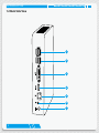
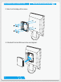
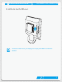
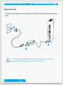
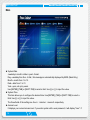
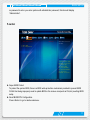
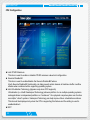
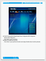
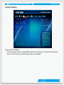
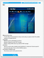
NanoPC
User’s Manual
Trademark:
All trademarks are the property of their respective owners.
Version:
User’s Manual V1.0 for NanoPC.
Symbol description:
Note:
Refers to important information that can help you to use NanoPC better, and tells you how to avoid problems.
UT
CA
IO
N
Caution: Indicating a potential risk of hardware damage or physical injury may exist.
WEEE:
The use of this symbol indicates that this product may not be treated as household
waste. By ensuring this product is disposed of correctly, you will help prevent potential
negative consequences for the environment and human health, which could otherwise
be caused by inappropriate waste handling of this product. For more detailed information about recycling of this product, please contact your local city office, your household waste disposal service or the shop where you purchased this product.
© All rights reserved.
All trade names are registered trademarks of respective manufacturers listed.
All images are for reference only, please refer to the physical product for specific features.
CA
UT
IO
N
Safety Notice:
Before using this product, please read the below safety notice carefully, this will help to
extend the product’s lifecycle, and work normally.
■ When NanoPC is working, please make sure its ventilation system is working.
■ The power adapter is dissipating heat during normal use, please be sure not to cover
it and keep it away from your body to prevent discomfort or injury by heat exposure.
■ Please use the power adapter that comes with the product’s package, wrong power adapter may damage your device.
■ Make sure all the peripherals are properly connected before using NanoPC.
■ This product should only be used in an environment with ambient temperatures between 0°C and 40°C.
■ Always shut down the computer before installing or uninstalling the peripheral which does not support hot plug.
■ Disconnect all peripherals before servicing or disassembling this equipment.
■ Please do not disassemble this product by yourself, any disassembly not approved by the original manufacturer may result in malfunction, and void warranty.
■ Risk of explosion if battery is replaced by an incorrect type, please dispose of used batteries according to the instructions.
■ The products’ support of mSATA is up to if Intel CPU can support it or not.
Package Contents
NanoPC
Seat Base
VESA Mount
Power Adapter
Power Cord
Easy Guide
U-Disk
USB Flash Disk
Screws
Mini PCIe Half Card Support
Bracket
We DO NOT guarantee it is in compliance with the Safety Certificates if you add on an
extension cable to NanoPC USB Flash Disk in the package.
TABLE OF CONTENTS
Introduction
1-1 Front Side View....................................................................................................... 2
1-2 Back Side View........................................................................................................ 4
Placement and connecting
2-1 Placement of NanoPC............................................................................................ 7
In Seat Base.............................................................................................................. 7
Installing to Display................................................................................................... 7
2-2 Connection of NanoPC......................................................................................... 10
Connect display....................................................................................................... 10
Connect USB devices............................................................................................. 11
Connect network cable............................................................................................ 11
Connect power cord................................................................................................ 12
BIOS Setup
Enter BIOS Setup........................................................................................................ 14
Main............................................................................................................................. 16
F-center....................................................................................................................... 17
Smart BIOS............................................................................................................. 18
CPU Configuration.................................................................................................. 20
Advanced..................................................................................................................... 22
Trusted Computing.................................................................................................. 23
North Bridge............................................................................................................ 24
Onboard Device Configuration................................................................................ 25
SATA Configuration................................................................................................. 26
Network Stack Configuration................................................................................... 27
Boot............................................................................................................................. 28
CSM parameters.................................................................................................... 29
Power........................................................................................................................... 30
Health.......................................................................................................................... 32
Security........................................................................................................................ 33
Save & Exit.................................................................................................................. 34
Install OS
4-1 Install Windows 7/8.1............................................................................................. 38
4-2 Install Drivers......................................................................................................... 42
Utility
Fox WINFLASH........................................................................................................... 44
1. Local Update....................................................................................................... 44
2. About & Help....................................................................................................... 46
Introduction
■ Front Side View
■ Back Side View
INTRODUCTION
1-1 Front Side View
1
2
3
4
5
6
7
2
INTRODUCTION
1
Power button with Power indicator LED
Press to turn your NanoPC on or off, the LED can indicate your system
states.
2
Speaker
3
USB 3.0 port
This USB port supports the USB 3.0/2.0/1.0 specification. Use this port for
USB devices such as keyboard, mouse, USB printer, USB flash drives and
hard disk drives, etc.
As to Windows 7 system, you need to install the USB 3.0 driver in NanoPC
USB Disk before using it.
4
Multi-Function card reader
This memory card reader supports SD/SDHC/SDXC/MS/MS Pro/MMC
memory cards used in devices like digital cameras, mobile phones, Media
players and so on.
5
Microphone
Connects to a microphone or playback devices with optical connectors
(3.5mm jack).
6
Headphone
Connects to a headphone.
7
Kensington lock
Attach a Kensington security system or a compatible security lock to secure
your NanoPC in place.
3
INTRODUCTION
1-2 Back Side View
1
2
3
4
5
6
7
4
INTRODUCTION
1
USB 2.0 port
This USB port supports the USB 2.0/1.0 specification. Use this port for USB
devices such as keyboard, mouse, USB printer, USB flash drives and hard
disk drives, etc.
2
USB 3.0 port
This USB port supports the USB 3.0/2.0/1.0 specification. Use this port for
USB devices such as keyboard, mouse, USB printer, USB flash drives and
hard disk drives, etc.
As to Windows 7 system, you need to install the USB 3.0 driver in NanoPC
USB Disk before using it.
3
DVI
DVI port
Connect monitor or TV that uses DVI connector to this port.
4
HDMI
HDMI port
The HDMI (High-Definition Multimedia Interface) port supports Full-HD
display devices.
Connect monitor or TV that uses HDMI connector to this port.
5
RJ-45 LAN port
Supports 10/100/1000Mb/s Ethernet network.
Connect network cable to access Internet.
6
Line out / SPDIF out port
Connects to powered analog speakers or recording devices with optical
connectors (3.5mm jack).
SPDIF function requires additional adapter and adapter cable.
7
Power input port
Connect power cord that come with your product.
5
Placement
and
connecting
■ Placement of NanoPC
■ Connection of NanoPC
PLACEMENT AND CONNECTING
2-1 Placement of NanoPC
In Seat Base
Place your NanoPC into the groove of the Seat Base.
Installing to Display
1. Assemble one side of the VESA mount.
7
PLACEMENT AND CONNECTING
2. Fasten it onto the display with four screws.
3. Fit the NanoPC into the VESA mount in the correct alignment.
8
PLACEMENT AND CONNECTING
4. Install the other side of the VESA mount.
To fasten the VESA mount, your display must comply with VESA75 or VESA100
standard.
9
PLACEMENT AND CONNECTING
2-2 Connection of NanoPC
Connect display
Connect a display or TV that has HDMI port to your NanoPC.
10
PLACEMENT AND CONNECTING
Connect USB devices
Connect USB devices to the USB ports, for example, mouse, keyboard devices.
As to Windows 7 system, you need to install the USB 3.0 driver in NanoPC USB disk before using the USB 3.0 ports.
Connect network cable
Connect one end of a network cable to the RJ-45 LAN port, and the other end to a hub or switch.
11
PLACEMENT AND CONNECTING
Connect power cord
Connect the power adapter to the power input port of the NanoPC, and then press the power button to start it.
2
3
UT
IO
N
1
CA
12
The power adapter is dissipating heat during normal use, please do not cover it and
keep it away from your body to prevent injury from heat exposure.
BIOS Setup
■
■
■
■
■
■
■
■
■
Enter BIOS Setup
Main
F-centre
Advanced
Boot
Power
Health
Security
Save & Exit
BIOS SETUP
Enter BIOS Setup
The BIOS is the communication bridge between hardware and software, correctly setting up the BIOS parameters is critical to maintain optimal system performance. Power on the computer, when the message
“Press <Del> to enter setup. Press <F7> to enter boot menu.”
appears at the bottom of the screen, you can press <Del> key to enter Setup.
We do not suggest that you change the default values in the BIOS Setup, and we shall
not be responsible for any damage which resulted from the change you made.
Use the arrow right/left keys to select a specific function and go to the submenu. Each function is explained below:
Main It displays the basic system configuration, such as CPU Name, memory size, system date, time and so on. They all can be viewed or set up through this menu.
F-Center
The advanced system features can be set up through this menu.
Advanced
The advanced system features can be set up through this menu.
Boot
Boot features can be set up through this menu. You can set the boot device priority and enable “Quiet Boot” feature here.
Power
All the items related with Green function features can be setup through this menu.
Health
This setup enables you to read/change fan speeds, and displays temperatures and voltages of your CPU/System.
Security
The Administrator/User password can be set up through this menu to prevent unauthorized use of your computer. If you set a password, the system will ask you to key in correct password before boot or access to Setup.
Save&Exit
The optimal performance settings can be loaded through this menu. However, it may offer better performance in some ways (such as less I/O cards, less memory ...etc.), still, it may cause problem 14
BIOS SETUP
if you have more memory or I/O cards installed. It means, if your system loading is heavy, set to optimal default may sometimes come out an unstable system. What you need now is to adjust BIOS setting one by one, trial and error, to find out the best setting for your current system. You also can save or discard the changes and exit BIOS setup here.
15
BIOS SETUP
Main
Main
F-center
Advanced
Boot
Power
Health
System Date
System Time
[Tue 11/18/2014]
[09:37:57]
Administrator
AT-9000 Series
10.0.29.1000
E61F1012
E61F1D16 12/03/2014 17:12:34
Access Level
Model Name
ME FM Version
EC Version
BIOS Version
Build Date and Time
Halt On
Security
Save&Exit
Set the Date. Use Tab
to switch between
Date elements.
[All, but keyboard]
CPU Brand Name:
Intel(R) Pentium(R) 3805U @ 1.90GHz
Total Memory
MAC Address
4096 MB (DDR3/DDR3L 1600)
30-OE-D5-BB-81-CD
→ ←: Select Screen
↑ ↓/Click: Select Item
Enter/Dbl Click: Select
+/-: Change Opt.
F1: General Help
F2: Previous Values
F3: Optimized Defaults
F4: Save & Exit
ESC/Right Click: Exit
Version 2.17.1246. Copyright (C) 0001 American Megatrends, Inc.
►System Date
<weekday><month><date> <year> format.
Day—weekday from Sun. to Sat., this message is automatically displayed by BIOS (Read Only).
Month—month from 1 to 12.
Date—date from 1 to 31.
Year—year, set up by users.
Use [ENTER], [TAB] or [SHIFT-TAB] to select a field. Use [+] or [-] to input the value.
►System Time
This item allows you to configure the desired time. Use [ENTER], [TAB] or [SHIFT-TAB] to select a field. Use [+] or [-] to input the value.
The three fields of the setting are <hour> : <minute> : <second> respectively.
►Access Level
It displays your current access level. If you enter system with a user password, it will display “User”. If 16
BIOS SETUP
no password is set or you enter system with administrator password, this item will display
“Administrator”.
F-center
Main
F-center
Super BIOS Protect
Advanced
Boot
Power
Health
[Enabled]
Security
Save&Exit
Super BIOS Protection
Settings.
▶ Smart BIOS
▶ CPU Configuration
→ ←: Select Screen
↑ ↓/Click: Select Item
Enter/Dbl Click: Select
+/-: Change Opt.
F1: General Help
F2: Previous Values
F3: Optimized Defaults
F4: Save & Exit
ESC/Right Click: Exit
Version 2.17.1246. Copyright (C) 0001 American Megatrends, Inc.
► Super BIOS Protect
To protect the system BIOS, there is a BIOS write-protection mechanism provided to prevent BIOS FLASH tool being improperly used to update BIOS or the vicious virus(such as CHI,etc) rewriting BIOS setup.
►Smart BIOS/CPU Configuration
Press <Enter> to go to relative submenu.
17
BIOS SETUP
Smart BIOS
Main
F-center
Advanced
Smart Power LED
Smart Boot Menu
Boot
Power
Health
[Disabled]
[Enabled]
Security
Save&Exit
Smart Power LED
Settings
→ ←: Select Screen
↑ ↓/Click: Select Item
Enter/Dbl Click: Select
+/-: Change Opt.
F1: General Help
F2: Previous Values
F3: Optimized Defaults
F4: Save & Exit
ESC/Right Click: Exit
Version 2.17.1246. Copyright (C) 0001 American Megatrends, Inc.
► Smart Power LED
Smart Power LED is a feature built on your motherboard to indicate different states during Power On Self Test (POST). The LED is located at the front panel, and it displays POST state by different long-
short blinking intervals. You can always leave this state enabled.
System Status
18
Power LED Status
Stop Blinking Condition
Normal
Always On
Always On
No Memory
Continue blinking On (1sec.), Off (1sec.)
Reboot & Memory OK
No Display
Continue blinking On (2sec.), Off (2sec.)
Reboot & Display OK
Post Error Message
Quick blinking twice (1/3sec. On, 1/3sec. Off),
one long On (1sec.), continuously.
Enter Setup or Skip
BIOS SETUP
► Smart Boot Menu
When PC starts, it will ask you to press [Del] key to enter setup or press [F7] key to enter smart boot
menu. If [Disabled] is selected, then pressing [F7] has no function. This also prevents user without
password trying to get into your computer through smart boot menu.
19
BIOS SETUP
CPU Configuration
Main
F-center
Advanced
Boot
Power
CPU Configuration
306d4
11
1900 MHZ
500 MHz
1900 MHz
2
Not Supported
Supported
Not Supported
Supported
Supported
Supported
Supported
Supported
L1
L1
L2
L3
L4
32 KB X 2
32 KB X 2
256 KB X 2
2 MB
Not Present
Limit CPUID Maximum
Execute Disabled Bit
Intel Virtualization Technology
EIST
Turbo
CPU C3 Report
CPU C6 Report
Security
Save&Exit
Disabled for Windows XP
CPU Brand Name:
Intel(R) Pentium(R) 3805U @ 1.90GHz
CPU Signature
Microcode Patch
Max CPU Speed
Min CPU Speed
CPU Speed
Processor Cores
Intel HT Technology
Intel VT-x Technology
Intel SMX Technology
64-bit
EIST Technology
CPU C3 state
CPU C6 state
CPU C7 state
Data Cache
Code Cache
Cache
Cache
Cache
Health
[Disabled]
[Enabled]
[Enabled]
[Enabled]
[Enabled]
[Enabled]
[Enabled]
→ ←: Select Screen
↑ ↓/Click: Select Item
Enter/Dbl Click: Select
+/-: Change Opt.
F1: General Help
F2: Previous Values
F3: Optimized Defaults
F4: Save & Exit
ESC/Right Click: Exit
Version 2.17.1246. Copyright (C) 0001 American Megatrends, Inc.
► Limit CPUID Maximum
This item is used to enable or disable CPUID maximum value limit configuration.
► Execute Disable Bit
This item is used to enable/disable the Execute Disable Bit feature.
Intel’s Execute Disable Bit functionality can help prevent certain classes of malicious buffer overflow
attacks when combined with a supporting operating system .
► Intel Virtualization Technology (Appears only when CPU supports)
Virtualization (i.e. Intel® Vanderpool Technology) allows a platform to run multiple operating systems
and applications in independent partitions or “containers.” One physical compute system can function
as multiple “virtual” systems. Vanderpool Technology can help improve future virtualization solutions.
This item will be displayed only when the CPU is supporting this feature and the setting is used to
enable/disable it.
► EIST
20
BIOS SETUP
You can select the EIST (Processor Power Management, PPM) through this item.
N
CA
UT
IO
Enhanced Intel SpeedStep® technology (EIST) allows the system to dynamically
adjust processor voltage and core frequency, which can result in decreased average
power consumption and decreased average heat production. There are some
system requirements must be met, including CPU, chipset, motherboard, BIOS and
operation system. Please refer to Intel Website for more information.
► Turbo Mode
This item is used to enable or disable Turbo Mode.
► CPU C3 Report
This item is used to enable or disable CPU C3 (ACPI C2) report to OS.
► CPU C6 report
This item is used to enable or disable CPU C6 (ACPI C3) report to OS.
Advanced
21
BIOS SETUP
Main
▶
▶
▶
▶
▶
F-center
Advanced
Boot
Trusted Computing
North Bridge
Onboard Device Configuration
SATA Configuration
Network Stack Configuration
Power
Health
Security
Save&Exit
Trusted Computing
Settings
▶Realtek PCIe GBE Family Controller
(MAC:00:00:00:00:00:03)
→ ←: Select Screen
↑ ↓/Click: Select Item
Enter/Dbl Click: Select
+/-: Change Opt.
F1: General Help
F2: Previous Values
F3: Optimized Defaults
F4: Save & Exit
ESC/Right Click: Exit
Version 2.17.1246. Copyright (C) 0001 American Megatrends, Inc.
► Trusted Computing/North Bridge/Onboard Device Configuration/SATA Configuration
/Network Stack Configuration
Press <Enter> to go to its submenu.
► Realtek PCIe GBE Family Controller
Press <Enter> to go to get driver information and configure Realtek ethernet controller patameter.
22
BIOS SETUP
Trusted Computing
Main
F-center
Advanced
Configuration
Security Device Support
Current Status Information
NO Security Device Found
Boot
Power
Health
[Enabled]
Security
Save&Exit
Enables or Disables
BIOS support for
security device. O.S.
will not show Security
Device. TCG EFI protocol and INTA interface
will not be available.
→ ←: Select Screen
↑ ↓/Click: Select Item
Enter/Dbl Click: Select
+/-: Change Opt.
F1: General Help
F2: Previous Values
F3: Optimized Defaults
F4: Save & Exit
ESC/Right Click: Exit
Version 2.17.1246. Copyright (C) 0001 American Megatrends, Inc.
► Security Device Support
This item is used to enable or disable BIOS support for security device. O.S. will not show Security
Device. TCG EFI protocol and INTA interface will not be available.
23
BIOS SETUP
North Bridge
Main
F-center
Advanced
Boot
Power
Health
Security
North Bridge Configuration
Memory Information Total Memory
DIMM#0
DIMM#1
Memory Configuration
Internal Graphics
DVMT Pre-Allocated
DVMT Total Gfx Memory
Save&Exit
Keep IGO enabled based
on the setup options.
4096 MB (DDR3/DDR3L 1600)
4096 MB (DDR3/DDR3L)
Not Present
[Auto]
[64M]
[256M]
→ ←: Select Screen
↑ ↓/Click: Select Item
Enter/Dbl Click: Select
+/-: Change Opt.
F1: General Help
F2: Previous Values
F3: Optimized Defaults
F4: Save & Exit
ESC/Right Click: Exit
Version 2.17.1246. Copyright (C) 0001 American Megatrends, Inc.
► Total Memory
This item displays the current using memory information.
► DIMM#0/#1
These items display the memory size installed on each slot.
► Integrated Graphics
This item allows you to determine whether to allocate memory for the integrated graphics controller
from the system memory. Options: [Auto], [Manual].
[Auto]-Auto the integrated graphics controller.
[Manual]- Manual the integrated graphics controller.
► DVMT Pre-Allocated
This item is used to select DVMT 5.0 Pre-Allocated (Fixed) Graphics Memory size used by the
Internal Graphics Devices.
► DVMT Total Gfx Memory
This item is used to select DVMT 5.0 Total Graphic memory size used by internal graphics device.
24
BIOS SETUP
Onboard Device Configuration
Main
F-center
Advanced
Boot
Power
Health
Security
Onboard Device Configuration
Onboard LAN Controller
USB Support
Legacy USB Support
Azalia
Save&Exit
Enabled/Disabled On-
[Enabled]
[Enabled]
[Enabled]
[Enabled]
board LAN Controller.
→ ←: Select Screen
↑ ↓/Click: Select Item
Enter/Dbl Click: Select
+/-: Change Opt.
F1: General Help
F2: Previous Values
F3: Optimized Defaults
F4: Save & Exit
ESC/Right Click: Exit
Version 2.17.1246. Copyright (C) 0001 American Megatrends, Inc.
► Onboard LAN Controller
This item is used to enable or disable the onboard LAN controller
► USB Support
This item is used to enable or disable USB Controller Support.
► Legacy USB Support
This item is used to enable the support for USB devices on legacy OS. If you have a USB keyboard or
mouse, set to enabled.
[Enabled]: This option will enable the legacy USB support.
[Disabled]: This option will keep USB devices available only for EFI applications.
► Azalia
This item is used to enable or disable the Azalia HD Audio Controller.
25
BIOS SETUP
SATA Configuration
Main
F-center
SATA Controller(s)
SATA Mode Selection
Serial ATA Port1
Serial ATA Port2
Advanced
Boot
Power
Health
[Enabled]
[AHCI]
Security
Save&Exit
Enabled or Disabled
SATA Device.
Empty
Empty
→ ←: Select Screen
↑ ↓/Click: Select Item
Enter/Dbl Click: Select
+/-: Change Opt.
F1: General Help
F2: Previous Values
F3: Optimized Defaults
F4: Save & Exit
ESC/Right Click: Exit
Version 2.17.1246. Copyright (C) 0001 American Megatrends, Inc.
► SATA Controller(s)
This item is used to enable or disable SATA controller.
► SATA Mode Selection
This item is used to set the operating mode of your SATA ports.
[AHCI] - The Advanced Host Controller Interface (AHCI) specification describes the register level
interface for a Host Controller for Serial ATA. The specification includes a description of the hardware/
software interface between system software and the host controller hardware. AHCI provides more
advanced features including SATA features, but some SATA drives may not support AHCI, unless they
are labeled with AHCI support in its specification. If your motherboard supporting AHCI, and you have
a SATA device, which also supports AHCI, then you can select IDE option to have fair performance
(only PATA, SATA level), or you can select AHCI to get its best performance.
[RAID] - When you enable RAID, it means all your SATA drives must also support AHCI.
26
BIOS SETUP
Network Stack Configuration
Main
F-center
Network stack
Advanced
Boot
Power
Health
[Disabled]
Security
Save&Exit
Enable/Disables UEFI
network stack
→ ←: Select Screen
↑ ↓/Click: Select Item
Enter/Dbl Click: Select
+/-: Change Opt.
F1: General Help
F2: Previous Values
F3: Optimized Defaults
F4: Save & Exit
ESC/Right Click: Exit
Version 2.17.1246. Copyright (C) 0001 American Megatrends, Inc.
► Network stack
This item is used to enable/disable UEFI network stack.
The UEFI(Unified Extensible Firmware Interface)Network Stack implements the TCP/IP network interfaces such as SNP, MNP,ARP, IP, UDP, DHCP, MTFTP, and
TCP.
27
BIOS SETUP
Boot
Main
F-center
Advanced
Boot
Power
Health
Boot Configuration Bootup Numlock State
[On]
Quiet Boot
Fast Boot
[Enabled]
[Disabled]
▶
Security
Save&Exit
Select the keyboard
NumLock state
CSM Configuration
FIXED BOOT ORDER Priorities
Boot Option #1
Boot Option #2
Boot Option #3
Boot Option #4
Boot Option #5
Boot Option #6
Boot Option #7
Boot Option #8
Boot Option #9
Boot Option #10
Boot Option #11
Boot Option #12
Boot Option #13
Boot Option #14
Boot Option #15
Boot Option #16
[UEFI Hard Disk]
[UEFI CD/DVD]
[UEFI USB Hard Disk]
[UEFI USB CD/DVD]
[UEFI USB Key]
[UEFI USB Floppy]
[UEFI USB Lan]
[UEFI Network]
[Hard Disk]
[CD/DVD]
[USB Hard Disk]
[USB CD/DVD]
[USB Key]
[USB Floppy]
[USB Lan]
[Network]
→ ←: Select Screen
↑ ↓/Click: Select Item
Enter/Dbl Click: Select
+/-: Change Opt.
F1: General Help
F2: Previous Values
F3: Optimized Defaults
F4: Save & Exit
ESC/Right Click: Exit
Version 2.17.1246. Copyright (C) 0001 American Megatrends, Inc.
► Bootup Numlock State
This item defines if the keyboard Num Lock key is active when your system is started. The available
settings are: On (default) and Off.
► Quiet Boot
This item is used to enable/disable the quiet boot.
[Disabled] : Displays the normal POST messages.
[Enabled] : Displays OEM customer logo instead of POST messages.
► Fast Boot
This item is used to enable or disable boot with initialization of a minimal set of devices required to
launch active boot option. This is no effect for BBS boot options.
► FIXED BOOT ORDER Priorities
These items are used to set the system boot order.
28
BIOS SETUP
CSM parameters
Main
F-center
Advanced
Boot
Power
Health
Compatibility Support Module Configuration CSM Support
Boot option filter
[Disabled]
Security
Save&Exit
Enable/Disable CSM
Support.
[UEFI and Legacy]
Option ROM execution
Network
Storage
[Do not launch]
[Legacy]
→ ←: Select Screen
↑ ↓/Click: Select Item
Enter/Dbl Click: Select
+/-: Change Opt.
F1: General Help
F2: Previous Values
F3: Optimized Defaults
F4: Save & Exit
ESC/Right Click: Exit
Version 2.17.1246. Copyright (C) 0001 American Megatrends, Inc.
► CSM Support
This item is used to enable or disable CSM Support.
► Boot option filter
This item controls what devices system can boot to.
► Network
This item controls the execution of UEFI and Legacy PXE OpROM.
► Storage
This item controls the execution of UEFI and Legacy Storage OpROM.
29
BIOS SETUP
Power
Main
F-center
Advanced
Boot
Power
Health
ACPI Sleep State
[S3]
Resume By USB Device(s)
Resume By Onboard LAN
Resume By RTC
Energy-using products
Restore AC Power Loss
[Enabled]
[Disabled]
[Disabled]
[Enabled]
[Power Off]
Security
Save&Exit
Select the highest
ACPI sleep state
the system will
enter when the
SUSPEND button is
pressed.
→ ←: Select Screen
↑ ↓/Click: Select Item
Enter/Dbl Click: Select
+/-: Change Opt.
F1: General Help
F2: Previous Values
F3: Optimized Defaults
F4: Save & Exit
ESC/Right Click: Exit
Version 2.17.1246. Copyright (C) 0001 American Megatrends, Inc.
ACPI (Advanced Configuration and Power Interface) is an open industry standard interfaces enabling
OS-directed configuration, power management, and thermal management of mobile, desktop, and
server platforms. It defines five sleeping states, they are :
S1 - The S1 sleeping state is a low wake latency sleeping state. In this state, no system context is lost
(CPU or chip set) and hardware maintains all system context. (also called Power On Suspend)
S2 - The S2 sleeping state is a low wake latency sleeping state. This state is similar to the S1 sleeping
state except that the CPU and system cache context is lost (the OS is responsible for maintaining the
caches and CPU context). Control starts from the processor’s reset vector after the wake event.
S3 - The S3 sleeping state is a low wake latency sleeping state where all system context is lost except
system memory. CPU, cache, and chip set context are lost in this state. Hardware maintains memory
context and restores some CPU and L2 configuration context. Control starts from the processor’s
reset vector after the wake event. (also called Suspend to RAM)
S4 - The S4 sleeping state is the lowest power, longest wake latency sleeping state supported by ACPI.
30
BIOS SETUP
In order to reduce power to a minimum, it is assumed that the hardware platform has powered off all
devices. Platform context is maintained. (also called Suspend to Disk)
S5 - The S5 state is similar to the S4 state except that the OS does not save any context. The system
is in the “soft” off state and requires a complete boot when it wakes. Software uses a different state
value to distinguish between the S5 state and the S4 state to allow for initial boot operations within the
BIOS to distinguish whether or not the boot is going to wake from a saved memory image.
► ACPI Sleep State
This item is used to set the energy saving mode of the ACPI function. When you select “S1 (POS)”
mode, the power is always on and computer can be resumed at any time. When you select “S3
(STR)” mode, the power will be down after a period of time. The status of the computer before it
entering STR will be saved in memory, and the computer can quickly return to previous state when
the STR function wakes.
► Resume By USB Device(s)
This item is used to enable or disable the USB device(s) to generate a wake up.
► Resume By Onboard LAN
This item is used to enable or disable the onboard LAN to generate a wake up.
► Resume By RTC
This item is used to enable or disable RTC alarm event to generate a wake up.
RTC is system real time clock.
► RTC Alarm Date(Days)
When Resume by RTC is enabled, select a specific date to generate a wake up.
► RTC Alarm Time(HH:MM:SS)
When Resume by RTC is enabled, select a specific time to generate a wake up.
► Energy-using product
This item is used to configure the DeepSx Mode configuration.
► Restore AC Power Loss
This item is used to set which state the PC will take with when it resumes after an AC power loss.
31
BIOS SETUP
Health
Main
F-center
Advanced
CPU Temperature
CPU Fan Speed
+3.3V
+5V SYS
CPU VCore
VDDR
CPU Shutdowm Temperature
CPU Smart Fan Control
Boot
Power
Health
:
:
:
:
:
:
+40 ˚C
3326 RPM
3.307V
+4.985 V
+1.117 V
+1.340 V
Security
Save&Exit
CPU Shutdowm
Temperature
[Enabled]
[Enabled]
→ ←: Select Screen
↑ ↓/Click: Select Item
Enter/Dbl Click: Select
+/-: Change Opt.
F1: General Help
F2: Previous Values
F3: Optimized Defaults
F4: Save & Exit
ESC/Right Click: Exit
Version 2.17.1246. Copyright (C) 0001 American Megatrends, Inc.
► CPU Shutdown Temperature
This item is used to set the system temperature upper limit. When the temperature exceedsthe set
value, the system will shut down automatically.This function works only when your operating system is
supporting ACPI.
► CPU Smart Fan Control
This option is used to enable or disable CPU smart fan function.
32
BIOS SETUP
Security
Main
F-center
Advanced
Password Description
Administrator Password
User Password
Boot
Power
Health
Security
Save&Exit
Set Administrator
Password
Not Installed
Not Installed
Administator Password
▶ Secure Boot menu
→ ←: Select Screen
↑ ↓/Click: Select Item
Enter/Dbl Click: Select
+/-: Change Opt.
F1: General Help
F2: Previous Values
F3: Optimized Defaults
F4: Save & Exit
ESC/Right Click: Exit
Version 2.17.1246. Copyright (C) 0001 American Megatrends, Inc.
► Administrator Password
This item is used to install or change administrator password.
After you input administrator password, it then will ask you to confirm the password.
► User Password
This item is used to install or change user password.
Only when there exists a Administrator password, then this setting can be activated.
► Secure Boot menu
Press <Enter> to go to its submenu.
33
BIOS SETUP
Save & Exit
Main
F-center
Advanced
Save Changes and Reset
Discard Changes and Reset
Restore Defaults
Boot
Power
Health
Security
Save&Exit
Reset the
system after saving
the changes.
Boot Override
→ ←: Select Screen
↑ ↓/Click: Select Item
Enter/Dbl Click: Select
+/-: Change Opt.
F1: General Help
F2: Previous Values
F3: Optimized Defaults
F4: Save & Exit
ESC/Right Click: Exit
Version 2.17.1246. Copyright (C) 0001 American Megatrends, Inc.
► Save Changes and Reset
If you select this option and press <Enter>, a message will be displayed in the screen.
Select [Yes] to save your changes and reset computer, select [No] or <ESC> to return to the main
menu.
► Discard Changes and Reset
If you select this option and press <Enter>, a message will be displayed in the screen.
Select [Yes] to exit setup utility and reset computer without saving your modifications, select [No] or <ESC> to return to the main menu.
► Restore Defaults
Optimal defaults are the best settings of this motherboard.
Always load the Optimal defaults after updating the BIOS or after clearing the CMOS values.
Select this option and press Enter, it will pop out a dialogue box to let you load the defaults. Select
<Yes> and then press <Enter> to load the defaults. Select <No> and press <Enter>, it will not load.
34
BIOS SETUP
By this default, BIOS have set the optimal performance parameters of system to improve the
performances of system components. But if the optimal performance parameters to be set cannot
be supported by your hardware devices (for example, too many expansion cards were installed), the
system might fail to work.
► Boot Override
BIOS auto detect the presence of connected devices, select the device you want to boot from and press <Enter>, then the system will directly boot from the selected devices. Select [Yes] to discard your modifications, select [No] or <ESC> to return to the menu.
35
Install OS
■ Install Windows 7/8.1
■ Install Drivers
INSTALL OS
What kinds of hardware and software you need here:
1. Windows 7/8.1 Install USB Disk / USB DVD-ROM drive and Windows 7/8.1 Install CD (Other purchase)
2. NanoPC USB Flash Disk (In this package)
Windows 7 and Windows 8.1 can’t be installed when “Launch CSM” is set to “Disabled” in
the BIOS setup.
4-1 Install Windows 7/8.1
1. Connect the Windows 7/8.1 Install USB Disk (or USB DVD-ROM drive) to one USB port of NanoPC.
2. Press power on button to turn on your computer.
3. Put the Windows 7/8.1 Install CD into the USB DVD-ROM drive if you use the USB DVD-ROM drive.
4. Computer will choose the boot device by BIOS default and start loading the files for installing the OS.
Please press <Del> key to enter BIOS Setup if you want to change the first boot device
for installing the OS.
5. When the installation windows popup, set the related items and click “Next” to continue, then click “Install now” button to start the setup.
6. When the license terms appear, choose accept and click “Next” to continue.
7. It will then ask you to select the installation type. Click “Custom (advanced)” to install a new copy of Windows.
37
INSTALL OS
8. The setup will display the hard disk partitions (160GB, in this example) of your system. If there were other systems (such as Linux) installed previously, you need select them and click “Drive options (advanced)” to delete them. When all partitions are clean, setup will display the biggest size of your hard drive.
38
INSTALL OS
9. In the hard disk size screen, you can click the “new” button to create partitions as you need.
In this example we are creating a 70GB partition to install Windows. Make your modifications and click “Apply”.
To ensure that all Windows features work correctly, Windows might create additional partitions for system files. So you will see a 100MB partition reserved by system after you create a partition. Select the 70GB partition and click “Next” to continue.
39
INSTALL OS
10. The setup program will then start to install Windows 7/8.1 on your hard disk. During the installation, your computer will restart several times.
40
INSTALL OS
11. When the installation is complete, setup will prepare your computer for it’s first use. You can then
follow the steps to select system settings, create an account, set a password...etc, until the whole process is completed.
4-2 Install Drivers
1. When the Windows 7/8.1 is completely installed, you have to install the necessary drivers before using the NanoPC. Connect the NanoPC USB Flash Disk to your system.
2. Waiting for a few seconds, the main menu will be displayed on the screen.
3. Use these options to install all the drivers for your system. You must click "Intel Chipset Driver" to install it first. After that, you can click ”One Click Setup” and then choose the items you want to install, or you can click on each individual driver to install it manually.
4. After installing all the drivers, you need to restart your NanoPC, then you can start using it.
41
Utility
■ Fox WINFLASH
UTILITY
Fox WINFLASH
Fox WINFLASH is a useful utility to backup and update your system BIOS.
Supporting Operating Systems:
■ Windows 7
■ Windows 8.1
1. Local Update
1-1 Local Update - BIOS Information
This page lets you know your system BIOS information.
Minimum
Exit
Toolbar
Show current BIOS
information
Note:BIOS Size 32Mb = 32M bit = 4M Byte
BIOS Size 16Mb = 16M bit = 2M Byte
Please refer to the physical motherboard for details.
43
UTILITY
1-2 Local Update - Backup BIOS
This page can back up your system BIOS. You can click “Backup BIOS”, and key in a file name, then click “Save” to finish the backup operation. The extension of this backup file is “.ROM” for AMI BIOS. Make sure you can remember the file name together with the directory which it is stored, prevented that you may need them to recover your BIOS later.
Key in a BIOS name
Click to Save
1-3 Local Update - Update BIOS
This page helps you to update your BIOS from a local file. After click “Update BIOS”, An alert
message will be displayed to ensure if you really want to continue, click “Yes” to confirm. A setup wizard will guide you to load a local BIOS file to finish the operation. You must remember from which directory to load your new BIOS file (with an extension of “.ROM” for AMI BIOS) before the setup wizard starts.
44
UTILITY
2. About & Help
This page shows some information about Fox WINFLASH.
45
Statement:
This device complies with part 15 of the FCC Rules. Operation is subject to the following two
conditions: (1) This device may not cause harmful interference, and (2) this device must accept any interference received, including interference that may cause undesired operation.
Warning:
FEDERAL COMMUNICATIONS COMMISSION INTERFERENCE STATEMENT
This equipment has been tested and found to comply with the limits for a Class B digital device, pursuant to part 15 of the FCC Rules. These limits are designed to provide reasonable protection against harmful interference in a residential installation. This equipment generates, uses and can
radiate radio frequency energy and, if not installed and used in accordance with the instructions, may cause harmful interference to radio communications. However, there is no guarantee that interference will not occur in a particular installation. If this equipment does cause harmful interference to radio or television reception, which can be determined by turning the equipment off and on, the user is
encouraged to try to correct the interference by one or more of the following measures:
▪ Reorient or relocate the receiving antenna.
▪ Increase the separation between the equipment and receiver.
▪ Connect the equipment into an outlet on a circuit different from that to which the receiver is
connected.
▪ Consult the dealer or an experienced radio/ TV technician for help.
Caution:
Any changes or modifications not expressly approved by the grantee of this device could void the user’s authority to operate the equipment.
RF exposure warning:
This equipment must be installed and operated in accordance with provided instructions and the antenna(s) used for this transmitter must be installed to provide a separation distance of at least
20cm from all persons and must not be co-located or operating in conjunction with any other antenna or transmitter. End-users and installers must be provide with antenna installation instructions and transmitter operating conditions for satisfying RF exposure compliance.
Warning statement for Europe:
Also, put in the manual which directive to fulfil and also which countries to sell the product.
Example of a text to tell which directive has been fulfilled:
Hereby, Foxconn, declares that this AT-9000 Series is in compliance with the essential requirements and other relevant provisions of Directive 1999/5/EC.”