1
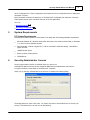
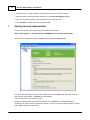
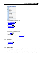
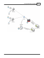
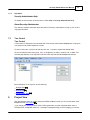
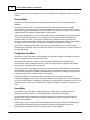
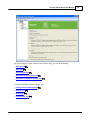
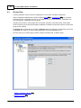
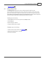
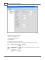
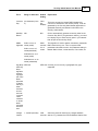
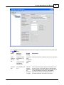
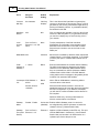
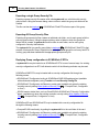
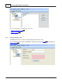
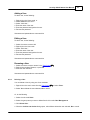
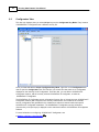
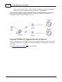
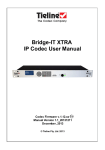
Security Administrator User
Manual
2
Security Administrator User Manual
Table of Contents
Part I Security Administrator User Manual
3
1 Technical
...................................................................................................................................
Support
3
2 Safety ...................................................................................................................................
Information
4
3 Preface
................................................................................................................................... 6
4 Introduction
................................................................................................................................... 8
5 System...................................................................................................................................
Requirements
9
6 Security
...................................................................................................................................
Administrator License
9
7 Starting
...................................................................................................................................
Security Administrator
10
7.1 Title and Menu
..........................................................................................................................................................
Bars
12
7.1.1 File Menu ......................................................................................................................................................... 12
7.1.2 Insert Menu......................................................................................................................................................... 13
......................................................................................................................................................... 13
7.1.3 Export Menu
Menu
13
7.1.4 Master Key.........................................................................................................................................................
7.1.5 Help Menu ......................................................................................................................................................... 17
7.2 Tree Control .......................................................................................................................................................... 17
8 Project
...................................................................................................................................
View
17
8.1 Groups View .......................................................................................................................................................... 20
.........................................................................................................................................................
a Group
21
8.1.1 Adding or Editing
Deleting
a
Group
.........................................................................................................................................................
27
8.1.2
Exporting
Groups
.........................................................................................................................................................
27
8.1.3
8.2 Users View .......................................................................................................................................................... 29
.........................................................................................................................................................
a User
30
8.2.1 Adding or Editing
Deleting
a
User
.........................................................................................................................................................
31
8.2.2
8.3 Configurators..........................................................................................................................................................
View
32
Adding
or
Editing
.........................................................................................................................................................
a
Configurator
33
8.3.1
......................................................................................................................................................... 34
8.3.2 Deleting a Configurator
Exporting
Configurators
......................................................................................................................................................... 34
8.3.3
2010
Security Administrator User Manual
I
3
Security Administrator User Manual
©2013 Control Microsystems Inc.
All rights reserved.
Printed in Canada.
Version: 8.05.4
The information provided in this documentation contains general descriptions and/or technical
characteristics of the performance of the products contained herein. This documentation is
not intended as a substitute for and is not to be used for determining suitability or reliability of
these products for specific user applications. It is the duty of any such user or integrator to
perform the appropriate and complete risk analysis, evaluation and testing of the products
with respect to the relevant specific application or use thereof. Neither Schneider Electric nor
any of its affiliates or subsidiaries shall be responsible or liable for misuse of the information
contained herein. If you have any suggestions for improvements or amendments or have
found errors in this publication, please notify us.
No part of this document may be reproduced in any form or by any means, electronic or
mechanical, including photocopying, without express written permission of Schneider
Electric.
All pertinent state, regional, and local safety regulations must be observed when installing and
using this product. For reasons of safety and to help ensure compliance with documented
system data, only the manufacturer should perform repairs to components.
When devices are used for applications with technical safety requirements, the relevant
instructions must be followed. Failure to use Schneider Electric software or approved
software with our hardware products may result in injury, harm, or improper operating results.
Failure to observe this information can result in injury or equipment damage.
1
Technical Support
Support related to any part of this documentation can be directed to one of the following
support centers.
2010
4
Security Administrator User Manual
Technical Support: The Americas
Available Monday to Friday 8:00am – 6:30pm Eastern Time
Toll free within North America
1-888-226-6876
Direct Worldwide
+1-613-591-1943
Email
[email protected]
Technical Support: Europe
Available Monday to Friday 8:30am – 5:30pm Central European Time
Direct Worldwide
+31 (71) 597-1655
Email
[email protected]
Technical Support: Asia
Available Monday to Friday 8:00am – 6:30pm Eastern Time (North America)
Direct Worldwide
+1-613-591-1943
Email
[email protected]
Technical Support: Australia
2
Inside Australia
1300 369 233
Email
[email protected]
Safety Information
Read these instructions carefully, and look at the equipment to become familiar with the
device before trying to install, operate, or maintain it. The following special messages may
appear throughout this documentation or on the equipment to warn of potential hazards or to
call attention to information that clarifies or simplifies a procedure.
The addition of this symbol to a Danger or Warning safety label
indicates that an electrical hazard exists, which will result in personal
injury if the instructions are not followed.
This is the safety alert symbol. It is used to alert you to potential
personal injury hazards. Obey all safety messages that follow this
symbol to avoid possible injury or death.
2010
Security Administrator User Manual
5
DANGER
DANGER indicates an imminently hazardous situation which, if not avoided, will
result in death or serious injury.
WARNING
WARNING indicates a potentially hazardous situation which, if not avoided, can
result in death or serious injury.
CAUTION
CAUTION indicates a potentially hazardous situation which, if not avoided, can
result in minor or moderate injury.
CAUTION
CAUTION used without the safety alert symbol, indicates a potentially hazardous
situation which, if not avoided, can result in equipment damage..
PLEASE NOTE
Electrical equipment should be installed, operated, serviced, and maintained only by qualified
personnel. No responsibility is assumed by Schneider Electric for any consequences arising
out of the use of this material.
A qualified person is one who has skills and knowledge related to the construction and
operation of electrical equipment and the installation, and has received safety training to
recognize and avoid the hazards involved.
BEFORE YOU BEGIN
Do not use this product on machinery lacking effective point-of-operation guarding. Lack of
effective point-of-operation guarding on a machine can result in serious injury to the operator
of that machine.
CAUTION
EQUIPMENT OPERATION HAZARD
Verify that all installation and set up procedures have been completed.
Before operational tests are performed, remove all blocks or other temporary
holding means used for shipment from all component devices.
2010
6
Security Administrator User Manual
Remove tools, meters, and debris from equipment.
Failure to follow these instructions can result in injury or equipment
damage.
Follow all start-up tests recommended in the equipment documentation. Store all equipment
documentation for future references.
Software testing must be done in both simulated and real environments.
Verify that the completed system is free from all short circuits and grounds, except those
grounds installed according to local regulations (according to the National Electrical Code in
the U.S.A, for instance). If high-potential voltage testing is necessary, follow
recommendations in equipment documentation to prevent accidental equipment damage.
Before energizing equipment:
Remove tools, meters, and debris from equipment.
Close the equipment enclosure door.
Remove ground from incoming power lines.
Perform all start-up tests recommended by the manufacturer.
OPERATION AND ADJUSTMENTS
The following precautions are from the NEMA Standards Publication ICS 7.1-1995 (English
version prevails):
Regardless of the care exercised in the design and manufacture of equipment or in the
selection and ratings of components, there are hazards that can be encountered if such
equipment is improperly operated.
It is sometimes possible to misadjust the equipment and thus produce unsatisfactory or
unsafe operation. Always use the manufacturer’s instructions as a guide for functional
adjustments. Personnel who have access to these adjustments should be familiar with the
equipment manufacturer’s instructions and the machinery used with the electrical
equipment.
Only those operational adjustments actually required by the operator should be accessible
to the operator. Access to other controls should be restricted to prevent unauthorized
changes in operating characteristics.
3
Preface
Scope
This manual covers the functionality and features included in Schneider Electric Security Administrator
software. It is applicable to Security Administrator version 2.11 and later.
The features described in this manual apply to the following controller platforms:
2010
Security Administrator User Manual
7
SCADAPack ES
SCADAPack ER
SCADAPack 314E
SCADAPack 330E
SCADAPack 334E
SCADAPack 350E
SCADAPack 357E
Purpose
This manual can be used in conjunction with Schneider Electric Security Administrator software
package for configuring security on SCADAPack E RTUs. The manual describes the use of Security
Administrator with SCADAPack E Configurator to deploy security settings.
Assumed Knowledge
It is assumed that the reader is familiar with basic concepts in SCADA (Supervisory Control and Data
Acquisition) and DNP3. The reader should also have familiarity with Microsoft Windows® operating
system and its basic user interfaces.
Target Audience
Systems Engineers
Commissioning Engineers
Maintenance Technicians
2010
8
4
Security Administrator User Manual
Introduction
What Is Security Administrator?
Security Administrator is a Windows® based security tool designed to configure security for
SCADAPack E controllers communicating using DNP3 and AGA12-2 standards.
Security Administrator is used to manage the security of SCADAPack E RTUs, and SCADAPack E
Configurator (the primary tool for configuring Schneider Electric SCADAPack E RTUs).
Security Administrator uses standard Windows features and styles such as tool bars, menus, and
property pages.
Using Security Administrator, you can:
Select one of three security modes:
DNP3 Secure Authentication
AGA12-2 Encryption
DNP3 Secure Authentication with AGA12-2 Encryption
Select one of three SCADAPack E Configurator key modes:
Default key (low security)
Common key (medium security)
Unique key (high security)
Generate secruity files with DNP3 Secure Authenticaton and AGA12-2 encryption security information
Configure each outstation to use a single, system-wide security key, a key file for sub-groups of
RTUs, or a key file for each RTU
Configure an RTU to use a single key pair for AGA12-2 encryption
Create, edit, and delete groups of RTUs
Define security settings for groups of RTUs
Create, edit, and delete users
Define security settings for users
Create, edit, and delete instances of SCADAPack E Configurator
Define security settings for SCADAPack E Configurator
Generate and export a license file for SCADAPack E Configurator
Deploy controller security configuration files for deployment from SCADAPack E Configurator to field
controllers
Typical Usage Scenario
Security Administrator is usually used by the person / people tasked with system security within an
organization ("security administration personnel").
Typically, Security Administrator does not reside on the same PC with an instance of SCADAPack E
Configurator. The security administration personnel use Security Administrator. to create master keys,
create users, create security configuration for groups of RTUs, set security modes, and create security
2010
Security Administrator User Manual
9
file for Configurator PCs. These configurations are Exported to secure configuration files for deployment
throughout a system.
Most companies will have more instances of SCADAPack E Configurator than instances of Security
Administrator and still more controllers than both of the PC applications.
Also see:
Exporting Groups
27
Exporting Configurators 34
5
System Requirements
PC System Requirements
Security Administrator operates on a Windows PC or laptop with the following hardware requirements:
Microsoft Windows XP, Windows Server 2003, Windows Vista, Windows Server 2008, or Windows
7, on 32-bit or 64-bit Operating System
Recommended: 2.2 GHz or higher CPU, 1 GB or more RAM, 1280x1024 display, 7200 RPM or
higher hard disk
100MB free disk space
Mouse (or other pointing device)
CD-ROM drive
6
Security Administrator License
Security Administrator requires an individual licence in order to run.
Individual RTU feature licenses are also needed for DNP3 Secure Authentication and AGA12-2
Encryption facilities to be enabled on SCADAPack E controllers.
When you run Security Administrator for the first time, it displays the following dialog:
The dialog displays a unique ‘Site Code’. You need to send this to Schneider Electric to receive your
site key. The easiest way to do this is to do the following:
2010
10
Security Administrator User Manual
1. Press the Copy To Clipboard button and paste into the body of an email message
2. Send the email to the email address specified on the License Configuration dialog.
3. Once you receive the site key, copy and paste it into the Site Key field.
4. Click Validate to activate your Security Administrator.
7
Starting Security Administrator
You can start Security Administrator using the Windows Start button.
Start>> All Programs >> Schneider Electric SCADAPack E >> Security Administrator
When Security Administrator opens, the Main dialog displays the Project View:
On the left, the tree displays the parent-level node known as the Project node. By default, when you
open Security Administrator, the Group sub-node displays.
You can only select one sub-node at a time.
The Security Administrator main window shows the main SCADAPack E Configurator window,
consisting of (in order from top of window) the title bar, menu bar, tree control (left-hand pane), property
page, splitter window, and status bar.
2010
Security Administrator User Manual
11
On the right, the modes you can configure for each sub-node selected on the left display. By default,
the Security Mode selected is DNP3 Secure Authentication. To change the any of the modes on this
dialog, click the appropriate radio button.
AGA12-2 Encryption: A system using AGA12-2 is secured using SCM (SCADA Crytopgraphic
module) devices. In the case of SCADAPack E RTUs, a virtual SCM is integrated with the RTU.
DNP3 Secure Authentication: A system using DNP3 Secure Authentication is secured through
groups where a security key (Group Common Key) is shared between the outstations and the DNP3
host.
DNP3 Secure Authentication with AGA-12-2 Encryption: A system using DNP3 Secure
Authentication with AGA12-2 Encryption is secured through groups where a security key (Group
Common Key) is shared between the outstations and the DNP3 host.
The Configuration Key Mode displays the security keys available. SCADAPack E Configurator Key
modes are available only if you select either DNP3 Secure Authentication or DNP3 Secure
Authentication with AGA12-2 Encryption. The three key modes are:
Default key: This option is the easiest one to use and maintain. However, there is a cost to such
simplicity: it offers the weakest level of security of the three key types. This key is the factory
default. The same factory default key is used for every controller Schneider Electric sells. Schneider
Electric recommends selecting one of the other key modes for a enhanced security level. If left
unchanged, this option does require user-based authentication from SCADAPack E Configurator and
the controller.
Common key: This option requires you deploy the same configurator security configuration file to
every instance of SCADAPack E Configurator. This means that you only need to maintain one key
for all your configurators. This offers a stronger level of security than using the default key. A
disadvantage of using common keys is that if the security on a laptop with SCADAPack E
Configurator is breached, the security configuration files need to be updated on instances of
SCADAPack E Configurator that you have deployed, as well as on every controller that is set to
request authentication. This option also requires user-based authentication from SCADAPack E
Configurator and the controller. If you select the radio button to change the default key to a common
key, you confirmation dialog displays indicating that changing the key requires you to re-deploy
keys to every security point in your network. To do so, click <OK>, to cancel this request, click
<Cancel>.
Unique key: This option is the most secure of the three key modes. Each instance of SCADAPack
E Configurator uses a specific SCADAPack E Configurator security configuration file that is linked to
the Machine ID on which SCADAPack E Configurator is installed and licensed. From the Security
Administrator, you can add, edit, and remove instances of SCADAPack E Configurator from your
system.
The Users Mode section displays the user-based authentication options. If a security file is not loaded
into SCADAPack E Configurator, this mode allows you to enable or disable that the user is
authenticated to communicate with the controllers. The two modes are:
No user authentication provided by the Controller (default setting)
Individual users can be configured and authenticated by the Controllers
After you select the security settings for the Security Administrator,, do the following:
select File >> Save from the main menu. The Save >> File dialog opens. By default, the location
the where the file is saved is your My Documents folder on your local hard drive.
Make necessary changes to the folder name and enter a filename to the file.
2010
12
Security Administrator User Manual
To complete the action, click <Save>.
If you change your security mode to AGA12-2 Encryption after you have configured either users or
SCADAPack E Configurator instances, a message is displayed telling you that changing you security
mode removes all security configuration for users and SCADAPack E Configurator instances you have
created.
For more information on using the Project View dialog, see:
Groups View
Users View
20
29
Configurators View
7.1
32
Title and Menu Bars
Title Bar
The title bar is a standard Windows® title bar. It consists of (from left to right):
Access button (Security Administrator Logo)
Current Project name
Application name (Security Administrator)
Minimize, maximize, and close application buttons on the right
Menu Bar
The Security Administrator menu bar consists of the following menus. From left to right, these menus
are:
Menu:
File
12
Insert
13
Export
13
Master Key Help
17
13
7.1.1
File Menu
The File menu contains commands to create, open, and save Security Administrator security
configuration files.
The Quick File list displays the recently used files (maximum number displayed is four).
2010
Security Administrator User Manual
13
For more information on the menus, see:
Title and Menu Bars
Insert Menu
13
Export Menu
13
Master Key Menu
Help Menu
7.1.2
12
13
17
Insert Menu
From this menu, you can do the following:
Add a Group
Add a User
21
30
Add an SCADAPack E Configurator Configurator
7.1.3
33
instance
Export Menu
From this menu, you can do the following:
Export Groups
27
Export Configurators 34
7.1.4
Master Key Menu
From this menu, you can manage master keys. The intention of the master key is to provide the security
boundary for RTUs and security administration to one organization or part of an organization.
The master key customizes the controller security configuration file generated by the Security
Administrator and read by the RTU.
2010
14
Security Administrator User Manual
This menu offers you two options:
Set Master Key
Generate Master Key for all Controllers
Generate Blank Master Key for all Controllers
To set a new master key, you need to enter a new pass phrase. When you create a new master key, it
needs to be updated locally in every RTU. In addition, the pass phrase needs to be entered on every
Security Administrator instance your organization uses.
Similar guidelines apply to selecting a new pass phrase that apply when setting passwords. Select a
phrase that you can easily remember but is not one someone else could guess by knowing a few facts
about you. For example, your wedding anniversary, date of birth, child's name or other information that
could be easily guessed. Use a combination of alpha-numeric characters and/or a combination of upperand lower-case characters.
Be certain to limit the knowledge of the pass phrase!
Make sure the master key files and its deployment to RTU devices is kept secure. Delete any copies of
the Master Key File from removable media and PC disks after the master key is deployed in RTU
devices.
The master key pass phrase is stored securely on the security administrator PC independent of Security
Administrator Project files.
2010
Security Administrator User Manual
2010
15
16
Security Administrator User Manual
Creating a new Master Key
To set a new Master key, do the following:
1. From the Master Key menu, select Set Master Key. The Master key dialog opens.
2. Enter a new Master Key phrase.
3. Click OK
4. Click Yes to acknowledge you are aware all controllers will need to be updated locally with the new
master key you are creating; click No to terminate the action.
Generating a Master Key for All Controllers
1. From the Master Key menu, select Generate a Master Key for All Controllers. The Browse for
Folder dialog opens. Select the folder where you want to store the Master Key file (system.key).
2. Click OK
Generating a Blank Master Key for All Controllers
In the event that a user has misplaced the master key file it may be necessary to disable security
temporarily. A blank master key is used to disable security for the RTU or Configurator.
1. From the Master Key menu, select Generate a Blank Master Key for All Controllers. The
Browse for Folder dialog opens. Select the folder where you want to store the Master Key file (system.
key).
2. Click OK
2010
Security Administrator User Manual
7.1.5
17
Help Menu
Security Administrator Help
To display the online version of this document, select Help >> Security Administrator Help.
About Security Administrator
This selection displays information about the version of Security Administrator running on your PC and
copyright information.
7.2
Tree Control
Tree Control
A Tree Control is displayed on the left-hand side of the Security Administrator Project view. Its purpose
is to group the sub-nodes together by function.
To select a sub-node, click the sub-node and click the '+' symbol to expand the desired folder.
Click on the desired name of the group, user, or configurator you want to rename, edit, or delete. The
selected page displays on the right-hand side of the Security Administrator Project view window.
More information on each option, see the following:
Groups View
Users View
20
29
Configurators View
8
32
Project View
This view displays when you create new projects (File >> New) or when you click on the parent node,
Project from the Tree Control 17 .
If you change your security mode to AGA12-2 Encryption after you have configured either users or
SCADAPack E Configurator instances, a message is displayed telling you that changing you security
2010
18
Security Administrator User Manual
mode removes all security configuration for users and SCADAPack E Configurator instances you have
created.
Security Mode
Choose the main security operating mode for the system defined by this Security Administrator
database.
AGA12-2 Encryption is used on licensed RTU devices to provide encryption services for DNP3
communication. It requires the use of a AGA12-2 Gateway for conversion of clear text DNP3 to cipher
text AGA12-2 (typically a SCADAPack ES RTU is used for this). AGA12-2 Encryption can be used with
a Master Station host supporting standard DNP3 communication.
DNP3 Secure Authentication is used on licensed RTU devices to provide DNP3 security authentication
services (so that critical operations such as controls and configuration changes are performed by
authorized devices or users). It can provide SCADAPack E Configurator security and User level
security. It requires that the Master Station host or a DNP3 Data Concentrator natively supports DNP3
and DNP3 Secure Authentication. (For example ClearSCADA and SCADAPack E RTUs).
DNP3 Secure Authentication and AGA12-2 Encryption provides DNP3 security services including
SCADAPack E Configurator security and User level security, along with AGA12-2 encryption services on
the same RTU device.
Configurator Key Mode
The selection of this mode affects how SCADAPack E configuration software is activated and secured
when using DNP3 security to SCADAPack E RTUs.
Default Key mode is the basic security mode used between SCADAPack E Configurator and
SCADAPack E security-enabled RTU devices. It does not require special configuration and operates
"out-of-the-box", providing a basic security level.
Common Key mode is a configuration mode using a system specific code SCADAPack E Configurator
and SCADAPack E security-enabled RTU devices. The key is included in the security configuration for
all secured RTU devices and is applied to all SCADAPack E Configurator installations using a common
configurator security file. It provides a medium security level.
Unique Keys mode is a configuration mode using specific codes for individual SCADAPack E
Configurator installations. Keys for all configurator installations are included in the security configuration
for all secured RTU devices. Authorization is provided to all SCADAPack E Configurators using a unique
configurator security file for each SCADAPack E Configurator installed. It provides the highest security
level.
Users Mode
The selection of this mode affects whether SCADAPack E RTUs require individual users to be
authenticated in order to perform critical operations when using DNP3 communication.
No user authentication provided by the Controllers indicates to all SCADAPack E Configurator and
SCADAPack E security-enabled RTU devices that individual user logon is not required in order to
perform critical operations.
Individual users can be configured and authenticated by the Controllers indicates to all SCADAPack E
Configurator and SCADAPack E security-enabled RTU devices that individual users must be
authenticated by SCADAPack E RTUs in order to perform critical operations.
2010
Security Administrator User Manual
By right-clicking the mouse of the tree control Project entry, you can do the following:
Insert Group
Insert User
21
30
Insert Configurator
33
Export All Group Security Files
28
Export All Configurator Security Files 35
For more information on project settings, see:
Starting Security Administrator
Groups View
Users View
20
29
Configurators View
2010
32
10
19
20
8.1
Security Administrator User Manual
Groups View
A Group represents common security configuration for one or more controllers (outstations).
Group configurations automatically include configured Users 29 and Configurators 32 . You can export
the Group security configuration so that you can deploy it to one or more outstations. Outstations can
only have security configuration from one Group.
Outstations that need to communicate with one another need to be in the same Group. Peer-to-peer
communications and communication between outstations and Data Concentrators need to use the same
group security settings.
The Groups view is shown when you select the Groups node in the tree view. The first time you access
the Groups view, there are no group names displayed on the Group Management list.
From this view, you can add a group, edit the currently selected group, or delete a group.
Adding or Editing a Group
Deleting a Group
21
27
2010
Security Administrator User Manual
Exporting Groups
8.1.1
21
27
Adding or Editing a Group
The Add/Edit Group selection lets you view or configure the specific details for a group.
The three DNP3 group configuration boxes are only visible when the project's security mode is either
DNP3 Secure Authentication or DNP3 Secure Authentication with AGA12-2 Encryption (shown below).
The two AGA12-2 group configuration boxes are only displayed when the security mode for the project is
AGA12-2 Encryption or DNP3 Secure Authentication with AGA12-2 Encryption.
To Add a group, do the following:
1. Select Insert from the menu bar or right-click on the Group sub-node.
2. Select Add group.
3. Rename the group, if required.
4. Change the default values as required.
To Rename a group, do the following:
1. Select the user account to rename in the Tree Control
2. Right-click and select Rename, or press F2.
3. Enter the new username.
2010
17
.
22
Security Administrator User Manual
To Edit group selections, do the following:
1. Right-click on the Group sub-node.
2. Select the group you want to edit.
3. Click Edit Group.
You cannot edit the group name from this view.
You can configure the following fields when DNP3 Secure Authentication is the security mode.
Field
Range or Selection
Allow
CompactFLASH,
Update of Configurator via USB
Security
CompactFLASH,
File
Configurator, Remote
Host
Default
Setting
Explanation
Compact Select the method to update security file on controllers.
FLASH,
Configur
ator,
Remote
Host
2010
Security Administrator User Manual
Field
Range or Selection
Default
Setting
Common 32 characters (0-9,A- Valid
Key
F)
key
displays
New Key
Button
N/A
HMAC
SHA-1 trunc to 4
Algorithm octets (serial)
SHA-1 trunc to 10
octets(networked)
23
Explanation
This is the security key (static DNP3 Update Key)
common to all devices in this security Group. It can be
generated by the Security Administrator application or
generated externally and entered in this field on the
Security Administrator.
N/A
Click to automatically generate a new key value for the
Common Key field. If you generate a new key, you need
to re-deploy keys to each security point in your network
that are part of this security Group.
SHA1
truncate
d to 4
octets
This algorithm is used to protect usernames, passwords,
DNP3 session keys, etc. This is a system wide
parameter and needs to match the parameter setting in
Master Station Hosts, remote devices, Peer nodes, etc.
SHA-256 trunc to 8
octets (serial)
SHA-256 trunc to 16
octets (networked)
2010
Key Wrap AES-128
AES Key
Wrap
algorithm
protects
cryptogra
phic k eys
within
applicatio
ns where
the k ey is
either
transmitt
ed over
insecure
communi
cation
channels
or stored
within
untrusted
environm
ents.
AES-128 Currently, this is the only cryptographic key type
supported
Change
Interval
1800
Select the period for session key changes between
seconds devices. E.g. between the RTU and Master Station Host
1 - 50,000 (seconds)
24
Security Administrator User Manual
Field
Range or Selection
Default
Setting
Explanation
Change
Count
10 - 60000
2000
Select the message count between session key changes
N/A
Checked To reduce the overhead of a challenge/response in DNP3
Secure Authentication,when this field is checked, the
RTU accepts the master station adding an authentication
response to the protocol request for critical function
codes (rather than forcing a challenge to every critical
message).
N/A
Uncheck Disables the outstation from issuing Aggressive Mode
ed
requests when sending critical function codes in Data
Concentrator or Peer messages.
Aggressiv
e Mode Accept
Requests
Aggressiv
e Mode Issue
Requests
Challenge 4-40
Data
Length
(bytes)
4
Session
Key
Length
(bits)
128
128, 192, 256, 384,
512, 1024
Maximum 0 – 10
Error
Count
2
The number of bytes of challenge data used in session
key negotiation and authentication challenge messages.
This is a system wide parameter and needs to match the
parameter setting in Master Station Hosts, remote
devices, Peer nodes, etc.
Indicates the length of session keys. This is a system
wide parameter and needs to match the parameter
setting in Master Station Hosts, remote devices, Peer
nodes, etc.
The number of consecutive security conditions for which
the RTU will return errors. After this number of errors,
security conditions are silently discarded. This setting
affects only the RTU on which the configuration is
deployed.
For more information on these parameters see the SCADAPack E Security Technical Reference.
When you select AGA12-2 encryption for your project's security mode, the following dialog displays:
2010
Security Administrator User Manual
25
You can configure the following fields when AGA12-2 Encryption is selected as the security mode from
the Main 10 dialog.
2010
Field
Range or
Selection
Default
Setting
Allow
Update of
Security
File
CompactFLASH,
Configurator via
USB
CompactFL Select the method to update security file on controllers.
ASH,
Configurato
r, Remote
Host
Common
Key
32 characters (0-9,
A-F)
CompactFLASH,
Configurator,
Remote Host
Valid key
displays
(default is
32characters
in length)
Explanation
This is the security key common to all devices in this
security Group. It is the DNP3 Secure Authentication
static Update Key and the AGA12-2 Encryption Key. It
can be generated by the Security Administrator
application by pushing the New Keys button, or
generated externally and entered in this field.
26
Security Administrator User Manual
Field
Range or
Selection
Default
Setting
Explanation
Common
Mac Key
64 characters
Valid key
displays
This is the AGA12 MAC (verification signature) key
common to all devices in this security Group. It can be
generated by the Security Administrator application by
pushing the New Keys button, or generated externally
and entered in this field.
New Keys
Button
N/A
N/A
Click to automatically generate a new key value for the
Common & Mac Key fields. If you generate a new key,
you need to re-deploy keys to each security point in
your network.
Local
Access
Port
Port 0 to Port 8,
None
Ethernet 1 or 2, and
None
To allow maintenance of the field controllers,
SCADAPack E Configurator communicates using a
dedicated Local Access Port on the field controller.
Select the port number to use as the local access
DNP3 port.
Mixed Mode N/A
Checked
Mixed mode is enabled by default to allow unprotected
cleartext frames to be routed untouched. If you disable
(uncheck) this option, cleartext DNP3 frames are not
routed.
SCM
Address of
Gateway 1
Blank
Enter the SCM address for the Main AGA12 Gateway.
The AGA12 messages are directed to this address
rather than to the destination DNP3 address where
they are converted from AGA12 ciphertext to DNP3
cleartext.Select AGA12 GW1 in the DNP Network
routing table to direct messages to the gateway device
on behalf of an upstream DNP address.
Blank
Add or Edit an SCM address, authorizing AGA12
communication to that device
1 - 65519
Counterpart SCM Address 1List
65519
3600
Session timeout:
10-86400
Select the SCM session timeout in seconds. An
established session will close after the period specified
and force re-negotiation. If you delete a counterpart,
you will need to confirm the deletion before the action
will complete.
Delete an SCM entry, removing authorization for
AGA12 communication to that device
Gateway
Mode
Disable - Enable
Unchecked Enables AGA12 Gateway mode in a device for
(disabled) encoding/decoding AGA12 ciphertext on behalf of a
cleartext client (e.g. Master Station Host)
Gateway
Port (Clear
Device)
Port 0 to Port 8,
Ethernet 1 or 2
Ethernet 1
Applies to AGA12 Gateway mode RTU only. This port
receives DNP3 data in cleartext (e.g. from a Master
Station Host) and encodes it for transmission on a
ciphertext port. Select the port to use.
2010
Security Administrator User Manual
Field
Range or
Selection
1-65519
SCM
Address of
Gateway 25
27
Default
Setting
Explanation
Disabled
Enter the SCM address for an additional Gateway. (Up
to 4 additional gateway references are provided in
addition to the Main AGA12 Gateway 26 configuration
this device sends to). This allows AGA12 messages to
be directed to other gateway addresses, e.g. in a multimaster configuration, or where an RTU routes received
messages from AGA12 nodes and distributes the
responses via multiple gateway devices. Conversion
from AGA12 ciphertext to DNP3 cleartext is performed
by the gateway. Select AGA12 GW2, AGA12 GW3,
etc in the DNP Network routing table to direct
messages to the specific gateway device on behalf of
an upstream DNP address.
For more information on these parameters see the SCADAPack E Security Technical Reference.
When you select DNP3 Secure Authentication and AGA12-2 Encryption for your project's security
mode, a dialog containing the above parameters is displayed.
8.1.2
Deleting a Group
You can delete a group using one of two methods:
1. Right-click on the group name from the Tree Control
17
.
2. Select Yes to delete the group selected; No to cancel.
Or, do the following:
1. Select the sub-node Groups.
2. Select the group name you want to delete from the list under Group Management.
3. Click Delete Group.
4. When the Confirm group delete dialog opens, select Yes to delete the group selected; No to
cancel.
8.1.3
Exporting Groups
Group security files are exported by the Security Administrator so that they can be deployed
to SCADAPack E RTUs.
An export of a Group includes all User 29 security information, Common Key
Key 11 Configurator 32 security information, as well as the configured Group
2010
11
30
or Unique
information.
28
Security Administrator User Manual
Exporting a single Group Security File
Exporting a group security file creates a file called system.rtk in a sub-folder with security
group's name. Using the browser dialog, select a folder in which the group sub-folder will be
created.
This file can then be deployed
28
to SCADAPack E field RTUs that are part of this group.
Exporting All Group Security Files
Exporting all group security files creates an individual sub-folder, one for each group (with the
security group's name). Using the browser dialog, select a folder in which the group subfolders will be created. A system.rtk file will be save in each folder, one for each group
configured in Security Administrator.
The system.rtk file in a specific group folder is deployed 28 to SCADAPack E field RTUs that
are part of that specific Group. Repeat this for each system.rtk group file until every field RTU
in every group has been loaded with the appropriate group security file.
Deploying Group configuration to SCADAPack E RTUs
A system.rtk file may be loaded to an SCADAPack E RTU in one of several ways. An existing
security configuration in an RTU will determine which of the following methods may be used:
SCADAPack 300E RTUs may be loaded with a security configuration file through the
following means:
SCADAPack E Configurator locally via SCADAPack 300E USB peripheral port (available
with authorized configurator) using Transfer >> Load Security Config File
SCADAPack E Configurator via Ethernet or serial ports (available only when the existing
controller security setting Allow Update of Security File 22 is "CompactFlash, Configurator
or Host")
SCADA master station Host, such as ClearSCADA's SCADAPack E Security Configuration
object, (available only when the existing controller security setting Allow Update of Security
File 22 is CompactFlash, Configurator or Host)
SCADAPack ES and SCADAPack ER may be loaded with a security configuration file
through the following means:
CompactFLASH card locally, by putting the system.rtk file in the root folder of the card
SCADAPack E Configurator via Ethernet or serial ports (available only when the existing
controller security setting Allow Update of Security File 22 is "CompactFlash, Configurator
or Host")
2010
Security Administrator User Manual
29
SCADA master station Host, such as ClearSCADA's SCADAPack E Security Configuration
object, (available only when the existing controller security setting Allow Update of Security
File 22 is CompactFlash, Configurator or Host)
8.2
Users View
This view displays when you select the Users sub-node from the tree view. The Users dialog displays a
read-only list of every user. You can add, edit the currently selected user, or delete a user. Before you
can delete a user, you need to confirm the action.
2010
30
Security Administrator User Manual
For more information on configuring users, see:
Adding or Editing a User
Deleting a User
8.2.1
30
31
Adding or Editing a User
The Users selection lets you view or configure the specific details for a user.
User configurations are provided to SCADAPack E RTU devices along with Group
exporting groups 34 .
20
configurations by
2010
Security Administrator User Manual
31
Adding a User
To add a user, do the following:
1.
2.
3.
4.
5.
6.
Right-click on the Users node, or
Select Insert from the menu.
Select "Add User."
Enter the name of the user.
Enter the password assigned to the user.
Re-enter the password.
Usernames and passwords are case sensitive.
Editing a User
To edit a user, do the following:
1.
2.
3.
4.
5.
6.
Select the user account to edit.
Right-click on the User node.
Select "Edit User."
Enter the name of the user.
Enter the password assigned to the user.
Re-enter the password.
Usernames and passwords are case sensitive.
Renaming a User
1. Select the user account to rename in the Tree Control
2. Right-click and select Rename, or press F2.
3. Enter the new username.
17
.
Usernames and passwords are case sensitive.
8.2.2
Deleting a User
You can delete a User by using one of two methods:
1. Right-click on the user's name from the Tree Control
17
and select Delete.
2. Select Yes to delete the user selected; No to cancel.
Or, do the following:
1. Select the sub-node Users.
2. Select the group name you want to delete from the list under User Management.
3. Click Delete User.
4. When the Confirm user delete dialog opens, select Yes to delete the user selected; No to cancel.
2010
32
8.3
Security Administrator User Manual
Configurators View
This view only displays when you select Unique keys as the Configurator Key Mode. Every instance
of SCADAPack E Configurator uses a different security file.
Once you have selected the Unique Configurator Key Mode, right-click on the Configurators subnode to open the Configurators view. The first time you access this view, there are no configurators
displayed on the read-only list of Configurators. From this view, you can add an SCADAPack E
Configurator instance, edit the currently selected SCADAPack E Configurator, or delete an
SCADAPack E Configurator.
The SCADAPack E Configurator security information (Common Key or Unique Keys per SCADAPack E
Configurator instance) that configured in the Security Administrator, are included in the controller
security configuration files generated for the outstations to authorize communication with specific
SCADAPack E Configurator installations. The SCADAPack E Configurator security information
(Common Key or Unique Keys) is deployed to each authorized instance of SCADAPack E Configurator
software.
For more information on configuring SCADAPack E Configurator, see:
Adding or Editing a Configurator
33
2010
Security Administrator User Manual
Deleting a Configurator
8.3.1
33
34
Adding or Editing a Configurator
The Add/Edit Configurator selection lets you view or configure the specific details for a SCADAPack E
Configurator instance.
The Machine Id field is required when using unique key mode 33 . Its value is entered from the number
provided by SCADAPack E Configurator's Security >> DNP3 Security Settings dialog. This Id is used to
generate a unique security configuration file authorizing a specific SCADAPack E Configurator
installation for operation with a group of controllers.
Using Common Key Mode
Where Common Key mode is used for Configurators, Security Administrator generates the common key
for SCADAPack E Configurator and outstation devices.
The "New Key" button should be used to generate a new key prior to configuring the system's devices
for the first time. The addition of a new configurator should not generally require a new key to be
generated unless every SCADAPack E Configurator key is to be changed at the same time.
To authorized SCADAPack E Configurator installations in the field, do the following:
1. Click New Key on the Security Administrator Project page to generate a new key (only if necessary).
Confirm that you want to generate a new key. Doing so will require update of security information to all
devices in a network.
2. Right-click on Configurators
3. Select Export Configurator Security File
4. Save the security file (common.csf) and send to the person using the SCADAPack E Configurator
5. Person using SCADAPack E Configurator deploys the security file he receives to the PC where the
SCADAPack E Configurator instance resides, using the SCADAPack E Configurator "DNP3 Security
Settings" Change button.
6. Security configuration files for controller (outstation) groups configured in this Project need to be
exported and deployed to each field controller in order for the controller to authorize connection from
the newly secured SCADAPack E Configurator.
Using Unique Key Mode
Where Unique Key mode is used for Configurators, the Machine ID for a remote instance of SCADAPack
E Configurator could be sent in an email, from the person using the SCADAPack E Configurator, to the
security administration personnel.
To add or edit SCADAPack E Configurator instances, do the following:
1. Person using SCADAPack E Configurator obtains the Machine Id (for the PC on which the
SCADAPack E Configurator instance resides) by using the SCADAPack E Configurator "DNP3
Security Settings" menu item.
2010
34
Security Administrator User Manual
2. Highlight the Machine Id field and copy and paste the code from the dialog into an email
3. The security administration personnel creates a configuration on Security Administrator PC by rightclicking on Configurators in the Tree Control 17
4. Select Add Configurator
5. Open the email from the containing the Machine Id
6. Copy and paste the Machine Id from the email into the Security Administrator Machine Id field
7. Click New Key to generate a new key. Confirm that you want to generate a new key
8. Right-click on Configurators
9. Select Export Configurator Security File
10. Save the security file (*.csf) and attach to a reply email to the person using the SCADAPack E
Configurator
11.Person using SCADAPack E Configurator deploys the security file he receives via email to the PC
where the SCADAPack E Configurator instance resides, using the SCADAPack E Configurator
"DNP3 Security Settings" Change button.
12.Security configuration files for controller (outstation) groups configured in this Project need to be
exported and deployed to each field controller in order for the controller to authorize connection from
the newly secured SCADAPack E Configurator.
8.3.2
Deleting a Configurator
You can delete an SCADAPack E Configuratorinstance of a user using one of two methods:
1. Right-click on the SCADAPack E Configurator's name from the Tree Control
17
. Select Delete
2. Select Yes to delete the group selected; No to cancel.
Or, do the following:
1. Select the sub-node Configurators
2. Select the Configurator's name you want to delete from the list under Configurator Management.
3. Click Delete Configurator
4. When the Confirm Configurator delete dialog opens, select Yes to delete the Configurator
selected; No to cancel.
8.3.3
Exporting Configurators
Configurator security files are exported by the Security Administrator so that they can be deployed to
authorized SCADAPack E Configurator installations.
Configurator security files can be exported when using Configurator Common Key
11 modes (not to Configurator Default Key mode).
11
and Unique Key
Information in the Common Key mode or Unique Key mode settings (for Configurators), is also included
2010
Security Administrator User Manual
in the Group configurations when Exporting Groups
27
35
to field RTU devices.
Exporting a common Configurator Security File
A Configurator security file can be exported when using Configurator Common Key
11
mode.
Using the Security Administrator Export menu, choose Export >> All Group Security Files to export
files for all groups or Export >> Specific Group Security File to export the security file for a single
group. Likewise, right-clicking on the Project node and selecting Export All Group Security Files will
export the security files for all groups.
A file called common.csf is exported. Using the browser dialog, choose a folder location to store the
security file.
Take care to keep the configurator security file secure! It is used to authorize SCADAPack E
Configurator installations that will operate with your system.
Exporting unique Configurator Security Files
When Configurator Unique Key 11 mode is configured using Security Administrator, a configurator
security file can be exported for each defined Configurator.
As part of the configuration activities for a configurator, the Machine-ID needs to be retrieved from
SCADAPack E Configurator's Security >> DNP3 Security Settings dialog. See Adding or Editing
Configurators 33 for more information.
Using the Security Administrator Export menu choose one of the following:
Export All Configurator Security Files
Using the browser dialog, choose a folder to store the security files. A .csf file is created in the
folder for each defined configurator, using the name of the configurator with the csf extension. e.
g. Laptop1.csf
Export Specific Configurator Security File
Choose the specific configurator from the drop-down list and using the browser dialog, choose a
2010
36
Security Administrator User Manual
folder to store the security file. A .csf file is created in the folder for the selected configurator,
using the name of the configurator with the csf extension. e.g. Laptop2.csf
Unique key mode configurator security deployments are more secure than default or common mode
deployments, as a specific configurator security file operates for installation of SCADAPack E
Configurator is valid for a single PC (laptop, etc) only.
Deploying SCADAPack E Configurator Security Configuration
Once a configurator security file is exported from Security Administrator, the file is sent to an end user
to load in to SCADAPack E Configurator. This authorizes SCADAPack E Configurator for use with the
RTU system.
See Adding or Editing a Configurator
33
for more information.
2010