1
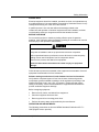
5915 SDI-12 Interface Module Installation, Operation and Maintenance Setup Manual 5/19/2011 Safety Information The information provided in this documentation contains general descriptions and/or technical characteristics of the performance of the products contained herein. This documentation is not intended as a substitute for and is not to be used for determining suitability or reliability of these products for specific user applications. It is the duty of any such user or integrator to perform the appropriate and complete risk analysis, evaluation and testing of the products with respect to the relevant specific application or use thereof. Neither Schneider Electric nor any of its affiliates or subsidiaries shall be responsible or liable for misuse of the information contained herein. If you have any suggestions for improvements or amendments or have found errors in this publication, please notify us. No part of this document may be reproduced in any form or by any means, electronic or mechanical, including photocopying, without express written permission of Schneider Electric. All pertinent state, regional, and local safety regulations must be observed when installing and using this product. For reasons of safety and to help ensure compliance with documented system data, only the manufacturer should perform repairs to components. When devices are used for applications with technical safety requirements, the relevant instructions must be followed. Failure to use Schneider Electric software or approved software with our hardware products may result in injury, harm, or improper operating results. Failure to observe this information can result in injury or equipment damage. © 2010 Schneider Electric. All rights reserved. Document (Version 2.24.1.84) 5/19/2011 2 Safety Information Table of Contents Safety Information .........................................................................5 About The Book .............................................................................8 At a Glance ............................................................................................................ 8 Overview .........................................................................................9 Installation ....................................................................................10 Field Wiring .......................................................................................................... 10 RS-232 Port ......................................................................................................... 11 SDI-12 Port .......................................................................................................... 12 Component Layout ............................................................................................... 13 Operation and Maintenance ........................................................15 LED Indicators ...................................................................................................... 15 Maintenance ......................................................................................................... 15 Troubleshooting ................................................................................................... 15 Specifications ..............................................................................17 General ................................................................................................................ 17 Power Requirements............................................................................................ 17 Communications – Port P1 .................................................................................. 17 Communications – Port P2 .................................................................................. 18 Indicators .............................................................................................................. 18 Approvals and Certifications ......................................................19 Document (Version 2.24.1.84) 5/19/2011 3 Safety Information Index of Figures Figure 1: SDI-12 module diagram ..................................................................... 10 Figure 2: Wiring of a system with multiple SDI-12 slave devices....................... 11 Figure 3: RS-232 DTE to RS-232 DTE without Handshaking ............................ 12 Figure 4: Component Layout ............................................................................. 14 Document (Version 2.24.1.84) 5/19/2011 4 Safety Information Safety Information Read these instructions carefully, and look at the equipment to become familiar with the device before trying to install, operate, or maintain it. The following special messages may appear throughout this documentation or on the equipment to warn of potential hazards or to call attention to information that clarifies or simplifies a procedure. The addition of this symbol to a Danger or Warning safety label indicates that an electrical hazard exists, which will result in personal injury if the instructions are not followed. This is the safety alert symbol. It is used to alert you to potential personal injury hazards. Obey all safety messages that follow this symbol to avoid possible injury or death. DANGER DANGER indicates an imminently hazardous situation which, if not avoided, will result in death or serious injury. WARNING WARNING indicates a potentially hazardous situation which, if not avoided, can result in death or serious injury. CAUTION CAUTION indicates a potentially hazardous situation which, if not avoided, can result in minor or moderate. CAUTION CAUTION used without the safety alert symbol, indicates a potentially hazardous situation which, if not avoided, can result in equipment damage.. Document (Version 2.24.1.84) 5/19/2011 5 Safety Information PLEASE NOTE Electrical equipment should be installed, operated, serviced, and maintained only by qualified personnel. No responsibility is assumed by Schneider Electric for any consequences arising out of the use of this material. A qualified person is one who has skills and knowledge related to the construction and operation of electrical equipment and the installation, and has received safety training to recognize and avoid the hazards involved. BEFORE YOU BEGIN Do not use this product on machinery lacking effective point-of-operation guarding. Lack of effective point-of-operation guarding on a machine can result in serious injury to the operator of that machine. CAUTION EQUIPMENT OPERATION HAZARD Verify that all installation and set up procedures have been completed. Before operational tests are performed, remove all blocks or other temporary holding means used for shipment from all component devices. Remove tools, meters, and debris from equipment. Failure to follow these instructions can result in injury or equipment damage. Follow all start-up tests recommended in the equipment documentation. Store all equipment documentation for future references. Software testing must be done in both simulated and real environments. Verify that the completed system is free from all short circuits and grounds, except those grounds installed according to local regulations (according to the National Electrical Code in the U.S.A, for instance). If high-potential voltage testing is necessary, follow recommendations in equipment documentation to prevent accidental equipment damage. Before energizing equipment: Remove tools, meters, and debris from equipment. Close the equipment enclosure door. Remove ground from incoming power lines. Perform all start-up tests recommended by the manufacturer. OPERATION AND ADJUSTMENTS The following precautions are from the NEMA Standards Publication ICS 7.11995 (English version prevails): Document (Version 2.24.1.84) 5/19/2011 6 Safety Information Regardless of the care exercised in the design and manufacture of equipment or in the selection and ratings of components, there are hazards that can be encountered if such equipment is improperly operated. It is sometimes possible to misadjust the equipment and thus produce unsatisfactory or unsafe operation. Always use the manufacturer’s instructions as a guide for functional adjustments. Personnel who have access to these adjustments should be familiar with the equipment manufacturer’s instructions and the machinery used with the electrical equipment. Only those operational adjustments actually required by the operator should be accessible to the operator. Access to other controls should be restricted to prevent unauthorized changes in operating characteristics. Document (Version 2.24.1.84) 5/19/2011 7 About The Book About The Book At a Glance Document Scope This manual describes the operation and maintenance of the 5915 SDI-12 Interface module. Validity Notes This document is valid for all versions of the 5915 SDI-12 Interface module. Product Related Information WARNING UNINTENDED EQUIPMENT OPERATION The application of this product requires expertise in the design and programming of control systems. Only persons with such expertise should be allowed to program, install, alter and apply this product. Follow all local and national safety codes and standards. Failure to follow these instructions can result in death, serious injury or equipment damage. User Comments We welcome your comments about this document. You can reach us by e-mail at [email protected]. Document (Version 2.24.1.84) 5/19/2011 8 Overview Overview The 5915 SDI-12 Interface Module facilitates communications between a slave instrument with SDI-12 interface and a master device that supports the SDI-12 protocol but has only RS-232 communications ports. The master device could be a SCADAPack controller or any other Industrial Controller or RTU that implement the SDI-12 protocol (such as Serck MGX). The master device could also be a PC based SCADA host (such as ClearSCADA). The 5915 SDI-12 Interface Module is a 5000 module and may be fully integrated into a DIN rail mounted controller system. However, it draws no current from the bus - this module requires an external power source. Light Emitting Diodes (LEDs) are provided to indicate communications activity on the SDI-12 bus. These LEDs can be disabled to conserve power. SDI-12 stands for Serial Data Interface at 1200 baud. Detailed information on this protocol is available on the internet at http://www.sdi-12.org Document (Version 2.24.1.84) 5/19/2011 9 Installation Installation The installation of the 5915 SDI-12 Interface Module requires mounting the modules on the 7.5mm by 35mm DIN rail. It is recommended that the system I/O bus be connected. This is necessary if I/O modules are to be connected downstream of this module. Refer to the System Configuration Guide for complete information on system layout, I/O Bus cable routing and module installation. For ATEX and IECx applications only: This equipment is to be installed in an enclosure certified for use, providing a degree of protection of IP54 or better. The free internal volume of the enclosure must be dimensioned in order to keep the temperature rating. A T4 rating is acceptable. Field Wiring The 5915 SDI-12 Interface Module provides two connectors: P1 is an RJ-45 for RS-232 connection from the SDI-12 master, and P2 is a four way screw termination style connector for connection to the SDI-12 bus. Figure 1: SDI-12 module diagram Figure 1: SDI-12 module diagram above shows the RJ45 (P1) connection at the bottom left hand corner, and the four way screw terminal (P2) at the bottom Document (Version 2.24.1.84) 5/19/2011 10 Installation right hand corner. The SDI-12 bus activity LEDs (TX and RX) are between the two connectors. Figure 2: Wiring of a system with multiple SDI-12 slave devices Figure 2: Wiring of a system with multiple SDI-12 slave devices above shows the connection of multiple SDI-12 slave devices connected to an SDI-12 master via the 5915 SDI-12 Interface Module. The 12V power supply can be physically located anywhere along the SDI-12 bus. The SDI-12 standard recommends that the total bus length be no longer than 200 feet (60 meters) and they also say that you can connect “at least 10” slave units, but no actual maximum number is listed. RS-232 Port Port P1 is a standard RS23DTE (Data Terminal Equipment) port and has fixed communications parameters. These are defined by the SDI-12 specification as 1200 Baud, 1 start bit, 7 bits (least significant bit transmitted first), even parity, one stop bit. For SCADAPack 32 controllers COM3 cannot be used as an SDI-12 port. P1 requires only the connection of TX, RX and Ground, as shown in the following table. Control Microsystems part number TBUM297303 is a 2 ft. cable that is available separately. DTE to DTE without Handshaking There are several methods for wiring the RS-232 COM port to DTE (Data Terminal Equipment) devices such as a SCADAPack controller. The simplest connection requires only 3 wires: RxD, TxD and signal ground. The following diagram shows a common RS-232 COM port to DTE device. This is referred to as a cross over cable. Document (Version 2.24.1.84) 5/19/2011 11 Installation RS-232 COM port (DTE) 8 Pin connector DTE DCD 2 DCD RxD 5 RxD TxD 6 TxD DTR 3 DTR GND 4 GND RTS 8 CTS 7 RTS + 5V 1 CTS See device specifications for pin numbers Figure 3: RS-232 DTE to RS-232 DTE without Handshaking Pin Function Description 1 2 3 4 5 NC NC NC GND RxD (input) 6 TxD 7 8 NC NC Not connected Not connected Not connected This pin is connected to the system ground. This level is SPACE on standby and MARK for received data. The LED is lit for a MARK level. This level is SPACE on standby and MARK for transmitted data. The LED is lit for MARK level. Not connected Not connected Table 1: P1 Wiring Connection SDI-12 Port The four way screw terminal connector (P2) can accommodate solid or stranded wires from 22 to 12 AWG. The pin connection for P2 is given in Table 2: P2 Wiring Connection below. Pin Description Pin 1 Pin 2 12V Pin 3 COM Not connected Input. Connect 9.6V to 16Vdc. Connect to zero volt rail of power supply, This is internally connected to chassis ground (EARTH). Document (Version 2.24.1.84) 5/19/2011 12 Installation Pin 4 Data SDI-12 Data line Table 2: P2 Wiring Connection Connector P2 is removable. This allows module replacement without disturbing the field wiring. Leave enough slack in the wiring for the connector to be removed. Remove power before servicing unit. To remove the SDI-12 connector (P2): Pull the connector upward from the board. Apply even pressure to both ends of the connector. To install the connector: Line up the pins on the module with the holes in the connector. Push the connector onto the pins. Apply even pressure to both ends of the connector. Component Layout Refer to Figure 4: Component Layout for component locations referred to elsewhere in this manual. Document (Version 2.24.1.84) 5/19/2011 13 Installation Figure 4: Component Layout Document (Version 2.24.1.84) 5/19/2011 14 Operation and Maintenance Operation and Maintenance LED Indicators The Model 5915 SDI-12 Interface Module has a red status LED for both SDI-bus TX and RX signals. This LED is on when data is present on the bus. Normal operation of the LEDs is both the TX and the RX LEDs will flash when the master station transmits and then the RX LED will flash with the response from the SDI-12 device Depending on the how the communications to the remote devices is configured, there may be long periods between communications. The LEDs can be disabled to conserve power. To select power saving modes, remove the lid and configure jumper J1 as per the following table. J1 is a three way header and is located toward the top, right hand side of the board. Jumper position Status LED mode Jumper loaded in left hand position Jumper loaded in right hand position Enabled. LEDs will light on bus activity. No jumper loaded LED power mode controlled by SCADAPack. LEDs will light on bus activity when allowed by SCADAPack. Refer to your controller board manual for details. LEDs off (lowest power consumption). Maintenance The 5915 SDI-12 Interface Module requires no routine maintenance or calibration. If a module is not functioning correctly, contact Control Microsystems Technical Support for more information and instructions on returning the module for repair. Troubleshooting Condition Action Transmit Data LED does not illuminate. Check the LED mode jumpers. Check 12Vdc supply. This happens when the Master Station transmits since each character is echoed back. Data radios generally will not transmit a Break control sequence (which is part of the SDI-12 protocol). Contact CMI Transmit and Receive LED come on at the same time. Won’t transmit over a data radio. Document (Version 2.24.1.84) 5/19/2011 15 Operation and Maintenance technical support. Document (Version 2.24.1.84) 5/19/2011 16 Specifications Specifications Disclaimer: Control Microsystems reserves the right to change product specifications. For more information visit www.controlmicrosystems.com . General SDI-12 bus Terminations Dimensions Packaging Environment Addressing 12 to 22 AWG 15A contacts Screw termination - 6 lb.-in. (0.68 Nm) torque 2.90 inch (74mm) wide 4.90 inch (124mm) high 1.80 inch (45mm) deep Corrosion resistant zinc plated steel with black enamel paint 5% RH to 95% RH, non-condensing o o o o –40 C to 70 C (–40 F to 158 F) operation o o o o –40 C to 85 C (–40 F to 185 F) storage None required. Power Requirements Power Input 12V power requirements 9.6V to 16VDC UL508 rating 12-14VDC. Class 2. 6mA Idle. 6.5mA active, with LEDs disabled 24mA active, continuous transmit, both LEDs on. Communications – Port P1 Port Type Connector Pins used Connection Protocol Baud Bits Document (Version 2.24.1.84) 5/19/2011 RS-232 compatible serial port 8 pin modular jack (RJ45) Only Transmit, Receive and Ground are connected. DTE SDI-12 only 1200 baud (as per SDI-12 protocol) 7 (as per SDI-12 protocol) 17 Specifications Parity Hardware handshaking Protection Even (as per SDI-12 protocol) None 15kV ESD protected. Communications – Port P2 Port Type Connector Pins used Protocol Protection SDI-12 port 4 way removable terminal block 12V, Ground, SDI Data SDI-12 only MOV and current limit Indicators Logic powered LEDs. Can be disabled to conserve power. TX RX Document (Version 2.24.1.84) 5/19/2011 Illuminates when transmitting data from Master Controller to a slave device on the bus. Illuminates when receiving data from a slave device AND when ever the Master Controller transmits. 18 Approvals and Certifications Approvals and Certifications Hazardous Locations North America Hazardous Locations Europe Hazardous Locations ATEX and IECEx Applications only Safety Digital Emissions Immunity Declaration Document (Version 2.24.1.84) 5/19/2011 Suitable for use in Class I, Division 2, Groups A, B, C and D Hazardous Locations. Temperature Code T4 CSA certified to the requirements of: CSA Std. C22.2 No. 213-M1987 - Hazardous Locations. UL Std. No. 1604 - Hazardous (Classified) Locations. ATEX II 3G, Ex nA IIC T4 per EN 60079-15, protection type n (Zone 2) IECEx, Ex nA IIC T4 per IEC 60079-15, protection type n (Zone 2) This equipment is to be installed in an enclosure certified for use, providing a degree of protection of IP54 or better. The free internal volume of the enclosure must be dimensioned in order to keep the temperature rating. A T4 rating is acceptable. For products using Solid State Relays (5415, 5606 and 5607 modules and SCADAPack using 5606 and 5607 modules) A T4 rating is acceptable for maximum loads of 2A. When 3A loads are connected to the Solid State Relays, the maximum ambient rating is lowered to 50°C in order to maintain the T4 rating. CSA (cCSAus) certified to the requirements of: CSA C22.2 No. 142-M1987 and UL916. (Process Control Equipment, Industrial Control Equipment) in Canada and USA. UL (cULus) listed: UL508 (Industrial Control Equipment) FCC Part 15, Subpart B, Class A Verification EN61000-6-4: 2001 Electromagnetic Compatibility Generic Emission Standard Part 2: Industrial Environment C-Tick compliance. Registration number N15744. EN61000-6-2: 2001 Electromagnetic Compatibility Generic Standards Immunity for Industrial Environments This product conforms to the above Emissions and Immunity Standards and therefore conforms with the requirements of Council Directive 2004/108/EC (as amended) relating to electromagnetic compatibility and is eligible to bear the CE mark. The Low Voltage Directive is not applicable to this product. 19 Approvals and Certifications Document (Version 2.24.1.84) 5/19/2011 20