1
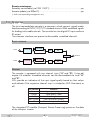
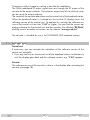
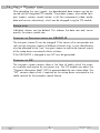
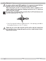
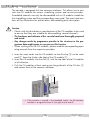
Head-End Digital Transmodulator 2 x DVB-C2/T2 QAM KLASSE HD2CT 800 C English CLASS GSS Grundig SAT Systems GmbH Beuthener Strasse 43 D-90471 Nuremberg Phone: Fax: E-mail: Internet: +49 (0) 911 / 703 8877 +49 (0) 911 / 703 9210 [email protected] http://www.gss.de/en Contents 1 Safety regulations and notes......................................................................... 4 2 General information..................................................................................... 5 2.1 Packing contents.............................................................................5 2.2 Meaning of the symbols used...........................................................5 2.3 Technical data................................................................................5 2.4 Description....................................................................................6 Block diagram................................................................................6 General.........................................................................................6 2.5 Software query..............................................................................7 2.6 How the TPS module works..............................................................8 Station filter...................................................................................8 Changing the Transport stream and ORGNET-ID................................8 Changing the NIT...........................................................................8 3 Assembly..................................................................................................... 9 3.1 Installing the cassette......................................................................9 3.2 EMC regulations...........................................................................10 3.3 Cassette overview........................................................................11 3.4 Connecting the cassette.................................................................11 3.5 Retrofitting a CA module...............................................................12 4 The control panel at a glance...................................................................... 13 4.1 Menu items..................................................................................13 4.2 Control panel...............................................................................13 5 Programming............................................................................................. 14 5.1 Preparation..................................................................................14 5.2 Notes on level setting....................................................................14 5.3 Programming procedure................................................................15 5.4 Programming the cassette .............................................................17 Selecting the cassette....................................................................18 Output settings.............................................................................18 Modulator on/off, Level...........................................................19 Channel / Frequency...............................................................19 Output symbol rate, QAM modulation ........................................ 20 Substitute signal in the case of an incorrect input signal................21 Input parameter............................................................................22 Kind of modulation..................................................................22 Input channel / frequency........................................................23 Operation with a CA module....................................................24 - 2 - HD2CT 800 C Station filter............................................................................24 PID monitoring........................................................................25 CA module.............................................................................26 Economize descrambling capacity.............................................27 Options.......................................................................................28 Transport stream ID and ORGNET-ID..........................................28 BAT/SDT-OTHER tables............................................................29 Deleting a PID.........................................................................29 Renaming a PID......................................................................30 Output data rate...........................................................................31 Network Information Table (NIT).....................................................31 Factory reset................................................................................33 Saving settings.............................................................................33 6 Final procedures......................................................................................... 34 7 Channel and frequency tables..................................................................... 35 - 3 - HD2CT 800 C 1 Safety regulations and notes • Assembly, installation and servicing should be carried out by authorised electricians. • Switch off the operating voltage of the system before beginning with assembly or service work or pull out the mains plug. • Do not perform installation and service work during thunderstorms. • Install the system so it will not be able to vibrate… - in a dust-free, dry environment -in such a manner that it is protected from moisture, fumes, splashing water and dampness - somewhere protected from direct sunlight - not within the immediate vicinity of heat sources - in an ambient temperature of 0 °C to +50 °C. In case of the formation of condensation wait until the system is completely dried. • Ensure that the head-end station is adequately ventilated. Do not cover the ventilation slots. • Beware of short circuits • No liability is accepted for any damage caused by faulty connections or inappropriate handling. • Observe the relevant standards, regulations and guidelines on the installation and operation of antenna systems. • The standards EN/DIN EN 50083 resp. IEC/EN/DIN EN 60728 must be observed. • For further information please read the assembly instructions for the headend station used. • Test the software versions of the head-end station and the cassette and update them if necessary. The current software versions can be found at "www.gss.de/en". Take action to prevent static discharge when working on the device! Electronic devices should never be disposed of in the household rubbish. In accordance with directive 2002/96/EC of the European Parliament and the European Council from January 27, 2003 which addresses old electronic and electrical devices, such devices must be disposed of at a designated collection facility. At the end of its service life, please take your device to one of these public collection facilities for proper disposal. - 4 - HD2CT 800 C 2 General 2.1 Pac k i n g contents 1 Cassette HD2CT 800 C 2 HF cables 1 Brief assembly instructions 2.2 M e a n i n g o f t h e s ym b o l s u s e d Important note —> General note • Performing works 2.3 T e c h n i c a l information data The devices meet the following EU directives: 2006/95/EC, 2004/108/EC The product fulfils the guidelines and standards for CE labelling (page 36). Unless otherwise noted all values are specified as "typical". RF input Frequency range:............................................................ 42 … 862 MHz Channel range:.........................C 05 …C 12, S 21 … S 41, C 21 … C 69 Input level:............................................................... 60 dBμV … 80 dBμV Input impedance:............................................................................. 75 Ω RF output Frequency range:.................................................... 42 MHz … 868 MHz Channels:............................................................................. S21 … C69 Output level:..................................................................... 90…100 dBμV Output impedance:.......................................................................... 75 Ω Connections: RF inputs: . ............................................................................. 2 F sockets HF output: . .......................................................................... 1 IEC socket Connection strip (10-pin):...................for supply voltages and control circuits RS-232 socket:...................................... serial interface for software update Common Interface:.......................2 (several channels can be descrambled). - 5 - HD2CT 800 C Remote maintenance Remotely controllable (via PSW 1000*):............................................... yes Remote update (via BEflash*):.............................................................. yes (* and a corresponding management unit) 2.4 D e s c r i p t i o n The twin transmodulator cassette is a converter, which converts signals modulated according to DVB-C/C2/T/T2 standard into two QAM modulated signals for feeding into a cable network. The cassette has two digital RF inputs and one RF output. Two common interfaces are present to descramble scrambled channels. B lo c k d i ag r a m IN "A" CA-Modul CA module Tuner "A" TPS Modulator "A" Combiner IN "B" TPS Modulator "B" General The cassette is equipped with two channel strips ("A" and "B"). Using adequate CA modules scrambled channels can be descrambled via tuner "A" and "B". LEDs provide an indication of the input signal quality based on their colour and indicate if the respective channel strip is switched on (LED illuminates) or off. CA-Modul CA module Tuner "B" RF OUT LED indicator Indication Green Signal quality is good Orange Signal quality is poor Red No signal Red<–>Green Data rate overflow (output) Off Channel strip (modulator) off The integrated TPS module (Transport Stream Processing) processes the data of the transport streams. - 6 - HD2CT 800 C Channel as well as frequency setting is possible for modulators. The QAM modulated RF output signals are sent through the RF output of the cassette to the output collector. The common output level of the channel strips can be set at the output collector. The control of the cassette takes place via the control unit of the head-end station. When the head-end station is switched on, the two-line LC display shows the software version of the control unit. To operate this cassette the software version of the control unit must be "V 44" or higher. You can find the current operating software for the control unit and the cassette, the software "BE-Flash" and the current assembly instructions on the website "www.gss.de/en". The cassette is intended for use in the STANDARD LINE head-end stations. 2.5 S o f t wa r e Control unit If necessary, you can activate the indication of the software version of the control unit manually: • Press any two keys on the control unit of the head-end station simultaneously until the display goes dark and the software version, e.g. "V 44" appears. q u e ry Cassette The software version of the cassette is shown in the display after activating the cassette (see page 18). - 7 - HD2CT 800 C 2.6 H ow t h e TPS m o d u l e wo r ks After decoding the input signals, the demodulated data streams can be accessed via the integrated TPS module. These data streams, also called transport streams, contain several stations in all their components (video, audio, data and service information), which can be changed using the TPS module. S tat i o n Individual stations can be deleted. This reduces the data rate and, consequently, the output symbol rate. Changing The transport stream ID can be changed. If the stations of a transponder are split into the transport streams of different channel strips, a new identification must be allocated to the "new" transport streams to realise the channel search of the settop boxes connected without mistakes. If the ORGNET-ID is changed a new NIT must be generated. Changing The transport stream contains data in the form of tables which the receivers evaluate and require for convenient use. The TPS module can adjust the "Network Information Table" (NIT) to accommodate the new station data. The "NIT" contains data which is required by the set-top boxes connected to the cable network for the automatic search feature. f i lt e r t h e T r a n s p o r t s t r e a m a n d ORGNET-ID t h e NIT - 8 - HD2CT 800 C 3 Assembly 3.1 I n s ta l l i n g the cassette – Ensure the head-end station is mounted so it will not be able to vibrate. Avoid, for example, mounting the head-end station onto a lift shaft or any other wall or floor construction that vibrates in a similar way. – Before installing or changing a cassette unplug the power cable from the mains power socket. • Remove the fastening screws 1 of an unoccupied slot from the bracket of the head-end station. • Insert the cassette in this slot and push it into the housing. • Align the cassette and apply slight pressure to connect it to the connections of the board and the HF bus bar. • Fasten the cassette with the screws 1. 1 HYBRID-VERSTÄRKER KASSETTE KASSETTE KASSETTE KASSETTE KASSETTE KASSETTE KASSETTE KASSETTE KASSETTE KASSETTE KASSETTE KASSETTE 0° ACHTUNG! Vor dem Kassettenwechsel unbedingt denNetzstecker ziehen. MESSAUSGANG –20 dBµV CAUTION! Before changing cassettes remove mains plug. AUSGANG max. 106 dBµV Grundig SAT Systems 1 - 9 - HD2CT 800 C 3.2 EMC KLASSE CLASS r e g u l at i o n s To comply with the current EMC regulations, it is necessary to connect the lines leading in and out of the head-end station using cable terminals. When mounting the cassette in a head-end station which is installed in a 19" cabinet, make sure the connections leading in and out for the 19" cabinet are made using cable terminals. The attenuation of shielding of the connection lines for ASI and antenna must meet the requirements for "Class A". • Insert the required number of cable terminals in the openings provided in the head-end station or in the 19" cabinet. Tighten the nuts on the cable terminals until the teeth on the lock washer have penetrated the exterior coating and a good connection is made between the housing and cable terminals. - 10 - HD2CT 800 C 3.3 C a s s e t t e ov e rv i e w 1 2 3 4 5 6 7 8 9 1 2 3 4 5 6 7 8 9 Slot for CA module of "tuner A" Slot for CA module of "tuner B" D-SUB socket "RS 232" Input "A" Status LED of channel strip "A" no function no function Status LED of channel strip "B" Input "B" The operating software of the cassette can be updated via the 9-pin D-SUB socket "RS 232" using a PC or notebook and the software "BE-Flash". You can find the current operating software on the website "www.gss.de/en". 3.4 C o n n e c t i n g the cassette • Connect "input A" 4 and "input B" 9 to corresponding signal sources. —> Avoid wide differences in level at the inputs! • Connect the head-end station to the mains power supply. - 11 - HD2CT 800 C 3.5 R e t r o f i t t i n g a CA m o d u l e The cassette is equipped with two common interfaces. This allows you to connect two CA modules for various scrambling systems and service providers. Scrambled channels can only be descrambled with a CA module suitable for the scrambling system and the corresponding smart card. The smart card contains all the information for authorisation, descrambling and subscription. Caution – Check with the distributor or manufacturer of the CA modules to be used to ensure that they are suitable for descrambling several channels. – The hardware and software of this cassette have been thoroughly prepared and tested. – Any changes made by programme provider to the structures in the programme data might impair or even prevent this function. – When working with the CA modules, please read the corresponding operating manuals from the respective providers. • Insert the smart cards into the CA modules so that the chip 3 on the smart card 1 faces the thicker side (top) of the CA module 2. • Insert the CA modules into the slots 4 with the top sides of the CA modules in left direction. • Push the CA modules without canting into the guide rails of the CA slots 4 and contact them to the common interfaces. 4 2 31 —> If the cassette is inserted in the head-end station, the left common interface is assigned to tuner A, the right one to tuner B. - 12 - HD2CT 800 C 4 The control panel at a glance 4.1 M e n u items Programme the cassette using the buttons on the control unit of the head-end station. The two-line display of the control unit then shows the menus. The parameters and functions to be set are underlined. Use the key to select the following main menu items: – Output signal settings: Modulator on/off, level BE-Remote V44 Output channel / Output frequency please wait . . . QAM modulation Substitute signal – Input signal settings: Kind of modulation Input channel / frequency Station filter CA module Economize descrambling capacity – Options: Transport stream and ORGNET-ID BAT, STD-other Deleting a PID Renaming a PID – Data rate – Network Information Table (NIT) – Factory reset 4.2 C o n t r o l The key pad on the head-end station is used to scroll through the menus stepby-step: scrolls forward through the menus. select parameters in the menus. set values, initiate actions. selects sub-menus. scrolls backward through the menus. saves all entries. pa n e l - 13 - HD2CT 800 C 5 Programming 5.1 P r e pa r at i o n • Test the software versions of the head-end station and the cassette and update them if necessary. The current software versions can be found on the website "www.gss.de/en". • Connect the test receiver to the HF output or the test output of the head-end station. • Set the output channel / output frequency of the cassette (page 19) and adjust the TV test receiver to this channel / frequency. • Switch on the channel strip (modulator) if necessary (page 19). For each channel strip, there is a status LED which indicates if the channel strip is switched on (5, 8 page 11). • Balance the output levels of the channel strips "A" and "B" if the difference in level is ≥ 1 dB (page 19). 5.2 N ot e s on level setting In order to prevent interference within the head-end station and the cable system, the output level of the cassette must be decreased by 10 dB compared to an analogous level at 64 QAM, and by 4 dB compared to analogue cassettes at 256 QAM. • Measure the output levels of the other cassettes and tune them to a uniform output level using the appropriate level controls or software dependent on the head-end station used. Please regard the assembly instructions of the respective head-end station. —> Avoid wide differences in level at the inputs! - 14 - HD2CT 800 C 5.3 P ro g r a m m i n g Ein / On BE–Remote pro c e d u r e V 44 please wait … t > 10 s Box 1 .............. .............. .............. Bedienhinweise "blättert" Menüs vorwärts. "blättert" Menüs rückwärts. wählen die Eingabeposition wählt Untermenü stellen Werte ein,. speichert alle Eingaben. 1 zeigt die Eingabeposition Operating Hints scrolls forward through the menu. scrolls backward through the menu. select the enter position. selects a submenu. set values and triggers actions. saves all entries. 1 shows the enter position + Box 4 V3 Bx 1A TWIN-SAT Böx 4 TWIN-SAT Box 5 .............. C5-12,S3-24 C07 C5-12,S3-24 C07 .............. .............. DVB-T2/C2 QAM – – – A Page 16 B Bx 4 Mod A OUTPUT C66 => ▶ LEVEL Bx 4A - 3 dB on on / off ◀ / ▶ 0 … -20 dB Mod A…B Mod B…A Modulator A/B Bx 4A FREQ C66 834.00 MHz ◀/▶ Mod A…B Mod B…A Bx 4A ! QAM–MODE 6900 QAM 256 ◀ / ▶ 1000…7500 4 … 256 POS/ NEG POS Mod A…B Mod B…A Bx 4A FAILURE Tables Tables / Single Carrier Mod A…B Mod B…A Bx 4 INPUT Tuner A OK => ▶ Bx 4A MODE T 8 MHZ OK QAM, COFDM 6…8MHz T/T2 5…8MHz ◀ / ▶ C/C2 6/8MHz Tuner A/B Bx 4A FREQ C55 746.00 Bx 4A TV + OK ◀/▶ 01/04 arte ◀/▶ alle + / alle – all + / all – Bx 4A CA-MENU PID Check on => ▶ Bx 4A ▶ Information *) 01/05 MENU ◀/▶ Bx 4A - 15SKIP - CA PID 1: 0x0000 HD2CT 800 C nur mit CA-Modul/ only with CA module *) Die angezeigte Information ist abhängig vom verwendeten CA-Modul. arte ◀/▶ alle + / alle – all + / all – Bx 4A CA-MENU ▶ Bx 4A => ▶ Information *) PID Check on 01/05 MENU ◀/▶ Bx 4A SKIP CA PID 1: 0x0000 PID 1…9 ◀/▶ Bx 4 OPTIONS A Bx 4A ▶ => TS/ONID 0x0001,0100 A/B off nur mit CA-Modul/ only with CA module *) Die angezeigte Information ist abhängig vom verwendeten CA-Modul. The information displayed is dependent on the CA module used. 0x0000 … 0xFFFF ◀ / ▶ on / off A…B B…A Bx 4A BAT/SDT bat sdt–other bat / BAT ◀ / ▶ sdt–other / SDT–OTHER A…B B…A Bx 4A DROP 0x0000 off ◀ / ▶ off / on A…B B…A Bx 4A REMAP 0x0000–>0000 off ◀ / ▶ off / on A…B B…A Bx 4A A DATARATE !!! 36/51 Mb aktuell/max. current/max. !!! Overflow A/B Bx 4A on / off off NIT => Make ▶ Make Page 15 Bx 4 Defaults FACTORY => ▶ Bx 4 FACTORY STORE => M - 16 - auf Werkseinstellung zurücksetzen und speichern M reset to factory defaults and store A B HD2CT 800 C 5.4 P r o g r a m m i n g the cassette —> Pressing the button for longer than 2 seconds cancels the programming procedure. This takes you back to the programme item "Selecting the cassette" from any menu. Any entries that have not been saved are reset to the previous settings. —> Entries in the menus can be saved by pressing the key. You are taken back to the "Selecting the cassette" menu item. —> The cursor position for settings is shown by "_". • Switch on the head-end station —> The display shows the software version (e.g. V 44). —> The processor reads the cassettes‘ data (approximately 10 seconds). Ein / On BE–Remote V 44 please wait … t > 10 s • Press the button. —> The "Selecting the cassette" – "Box x …" menu is activated. - 17 - HD2CT 800 C Selecting the cassette Box 1 .............. .............. .............. + Box 4 V3 Bx 1A TWIN-SAT Böx 4 TWIN-SAT Box 5 .............. C5-12,S3-24 C07 C5-12,S3-24 C07 .............. .............. DVB-T2/C2 QAM – – – • Select the cassette you want to programme (e.g. Box 4) by repeatedly pressing the button if necessary. —> The display shows e.g. the menu : Box 4 DVB-T2/C2 V3 QAM "Box 4" stands for slot 4 "DVB-T2/C2 QAM" Type of cassette "V 3" Software version of the cassette • Press the button. —> The "Output settings" – "OUTPUT" main menu is activated. O u t pu t In this menu you select the modulator for which you would like to do the output settings in the related submenus. s e t t i n gs Bx 4 Mod A OUTPUT C66 => —> In order to skip the "Output settings", press button . —> For example an indicated "C66" shows the current channel set. If "C – –" is displayed a frequency which does not correspond to the DVB-T channel-/frequency grid was set. —> It is possible to rotate through the submenus of the modulators using the buttons and . • Using buttons • Press the button. select the desired modulator. —> The "Modulator on/off, Level" – "LEVEL" submenu is activated. - 18 - HD2CT 800 C M o d u l ato r This menu item is used to set the output levels of the four modulators to the same value and to switch the modulators on or off. o n /o f f, L e v e l Bx 4A/B LEVEL on – 3 dB • Measure and note down the output level of each modulator. —> To adjust the output levels to the output levels of the other cassettes please pay attention to chapter "Final procedures" (page 34). • Using the buttons (ascending) or (descending) activate the "LEVEL" menu of all the modulators with higher output levels. • By pressing adjust the higher output levels to the output level of the modulator with the lowest output level incrementally. • Use the • Use the • Press the button to place the cursor under "on" resp. "off". buttons to switch each modulator on or off. button. —> The "Channel / Frequency" – "FREQ" submenu is activated. C h a n n e l / F r e q u e n c y In this menu you adjust the output channel (only at modulator A + C) or the output frequency of the respective modulator. —> The QAM signal is normally transmitted with a bandwidth of 8 MHz. This means that you can only use the channel centre frequency of the existing channel grid in the range of channels C21…C69 (frequency grid 8 MHz). The CCIR channel grid is 7 MHz in the range of the lower frequency bands (channels C5 … C12). If 8 MHz QAM signal packages are transmitted in these channel ranges, this will result in interference (overlapping) and transmission problems. For programming in these channel ranges and in the frequency ranges below them, we recommend starting with frequency 306 MHz going back in steps of 8 MHz (see frequency table on page 35). Please note thereby that many receivers cannot receive the channel ranges S21 … S41 (306 … 466 MHz). - 19 - HD2CT 800 C Channel setting: Bx 4A/B C66 FREQ 834.00 MHz • Use buttons • Use buttons to select the cursor position for channel setting. to adjust the desired channel. Frequency setting (42,0 MHz … 860,0 MHz): FREQ Bx 4A/B C66 834.00 MHz • Use buttons • Use buttons to select the cursor position for frequency setting. to adjust the desired frequency. • Press the button. —> The "Output symbol rate, QAM modulation" – "QAM-MODE" submenu is activated. Output s ym b o l r at e , QAM m o d u l at i o n In this menu you can set the output symbole rate, the QAM modulation and invert the user signal. Bx 4A ! QAM–MODE 6900 QAM 256 POS Output symbole rate: In this menu item you can set the output symbole rate. • Use the buttons to place the cursor under the number to be changed of e.g. "6900" and set the symbol rate with the buttons . —> A displayed "!" indicates an output data overflow (page 31). Bx 4A ! QAM–MODE In this case increase the output symbol rate or the QAM modulation or remove stations from the data stream using the station filter. - 20 - HD2CT 800 C QAM-Modulation: In this menu item you can set the QAM modulation. —> For higher QAM modulation, the output symbol rate is lowered. An output QAM modulation of > 64 QAM places a large burden on the cable network. Due to noise, delay and frequency response problems, reception of the converted output signal can be affected. • Use the buttons to place the cursor under "QAM…". Bx 4A ! QAM–MODE 6900 QAM 256 POS • Use to set the QAM modulation ("4" … "256"). Inverting the user signal: For exceptional cases and "older" digital cable receivers, the spectral position of the user signal can be inverted "NEG". Factory default is "POS". • Use to place the cursor under "POS". Bx 4A ! QAM–MODE 6900 QAM 256 • Use • Press the POS to set the spectral position to "NEG". button. —> The "Substitute signal in the case of an incorrect input signal" – "FAILURE" submenu is activated. Substitute You use this menu to set whether a "Single Carrier" signal should be provided or the self-made tables "Tables" should transmitted furthermore whenever an incorrect input signal occurs. signal in the case of an incorrect input signal Bx 4A/B FAILURE Tables - 21 - HD2CT 800 C • Use the • Press the buttons to set the required output signal. button. —> Returning to "Output settings" main menu (page 18). —> If necessary set a further modulator. • Press the button. —> The "Input parameter" – "INPUT" main menu is activated. Input In this menu you select the tuner for which you would like to do the input parameter in the related submenus. pa r a m e t e r Bx 4 INPUT Tuner A OK => —> In order to skip the "Input parameter settings", press button —> "OK" indicates a present input signal. • Using the buttons • Press button . select the desired tuner. . —> The "Kind of modulation" – "MODE" submenu is activated. Kind In this menu set the kind of modulation and the symbol rate (only QAM) of the input signal. o f m o d u l at i o n Bx 4A/B MODE T 8 MHZ OK • Select the kind of modulation of the transponder (T 6/7/8 MHz, T2 5/6/7/8 MHz, C2 6/8 MHz, C) using buttons . - 22 - HD2CT 800 C • Press the button. —> The "Input channel / frequency" – "FREQ" submenu is activated. Input In this menu you set the input channel / input frequency of the transponder you would like to receive. channel / frequency Bx 4A/B C55 FREQ 746.00 OK • Use buttons to position the cursor under the digit of the frequency resp. channel displayed to be set. • Press buttons to set the desired channel/frequency. —> Once the RF receiver has synchronised to the input signal, "OK" is displayed. —> If "– –" appears in the second line of the display, there is no input signal present. Check the configuration of the antenna system and the head-end station as well as the preceding settings of the module. —> The quality of the received transport stream is indicated by a status LED: LED indicator Green Indication Signal quality is good Signal quality is insufficient No signal Yellow Red • Press the Blinking red/green Data overflow of the output data rate Off The channel strip (modulator) is switched off button. —> The "Station filter" – e.g. "01/06" submenu is activated. - 23 - HD2CT 800 C O p e r at i o n with a CA m o d u l e In order to descramble scrambled channels a corresponding smart card is needed. The channels to be descrambled are set in submenu "station filter". S tat i o n In this menu stations (services) of a transponder can be switched off. Herein you select which scrambled station should be descrambled using an adequate CA module. f i lt e r Bx 4A/B TV + 01/04 arte —> All stations from the channel strip will be read, and then displayed with name and station type. —> If no station is found, the following error message will appear in the display: "FILTER no Service". In this case, check the configuration of the antenna system and head-end station, as well as the previously adjusted settings for the cassette. —> The display shows e.g.: Bx 4A TV + 01/04 arte Meaning of the indicators in the example: "Bx 4A" Slot 4, channel strip "A" "TV" TV channel type " + " The currently selected station is switched on. "01/04" The 1st of 4 stations is being displayed. "arte" Station name Further possible terms displayed: "RA" Radio channel type For radio stations, the background of the screen of the connected TV or test receiver is darkened. "–" The currently selected station is switched off. " * " The star means that the TV or radio station selected is encoded. To enable the stations, the CA module and the appropriate smart card of the station provider are required. - 24 - HD2CT 800 C —> If a service number (e.g. "131") appears instead of "TV" or "RA", this indicates that an unnamed station or an undefined data stream is being received. • Use the buttons to call up the stations in sequential order, then use to activate (indicated by " + ") or to deactivate them (indicated by " – "). —> Using button all station can be activated/deactivated. —> If a station is scrambled (indication "*"), in this menu you select whether it should be descrambled using an adequate CA module. • Press button twice to descramble a station (indication "X"). Bx 4A/B TV * X • Press the 01/04 button. —> The "PID monitoring" – "CA" submenu is activated. PID m o n i to r i n g In this menu you can switch off the PID monitoring and call up a menu for the settings of the CA module (dependent on the CA module). Bx 4A/B CA PID Check on => PID monitoring: —> The factory default of the PID monitoring is switched on. If particular PIDs are not descrambled the CA module is reset. Additionally dropouts may occur if several stations are decrypted. To prevent this the PID monitoring can be switched off. • Use the Menu of the CA module: buttons to switch "off" or "on" the PID monitoring. - 25 - HD2CT 800 C • Use the button to activate the menu of the CA module. —> Access to this menu is only possible with installed CA module and inserted smart card. CA m o d u l e The menu varies according to which CA module you are using. For this reason, please refer to the operating manual of your particular CA module. The relevant information is shown in the display of the head-end station. This may appear as a fixed display or as scrolling text according to display capabilities. Bx 4A/B CA ▶ Bx 4A/B 01/05 MENU PID Check on => ▶ Information *) —> The display shows e.g.: Bx 4A 01/05 MENU Meaning of the indicators: "Bx 4A" Slot 4, channel strip "A" "01/05" The first of five menu items is activated. "MENU" The menu of the CA module is activated. For the explanation of further details please use the operating instructions of the CA module used. • Use the buttons to activate the menu desired. • Press the button to activate the menu. • Use the buttons to select the function desired. • To set the CA module use the and buttons. —> By pressing the button you can cancel the settings in the menu of the CA module and are returned to the "PID monitoring" – "CA PID-Check" menu. • All settings are saved by pressing the button. —> You will be returned to the "PID monitoring" – "CA PID-Check" menu. • Press the button. —> The "Economize descrambling capacity" – "SKIP CA" is activated. - 26 - HD2CT 800 C Economize In this menu up to 9 not needed PIDs (e.g. audio PIDs of foreign language versions) can be excluded from the descrambling in order to economize descrambling capacity. d e s c r a m b l i n g c a pac i t y Bx 4A/B PID 1: SKIP CA 0x0000 • Using buttons select the desired memory location (PID 1…9) . • Use to position the cursor under the digit of PID to be set. • Press to set the respective digit of the PID needed. • Repeat the procedure by the quantity of the digits to be set. —> If required select another memory location and enter the next PID which shall not descrambled. —> To delete a stored PID, overwrite it by "0000". • Press the button. —> Returning to "Input parameter" - "INPUT" main menu (page 22). —> If required set further channel strips. • Press the button. —> The "Option settings" – "OPTIONS" main menu is activated. - 27 - HD2CT 800 C Options In this menu you select the channel strip for which you would like to do the option settings in the related submenus. Bx 4 OPTIONS A => —> In order to skip the "Option settings", press button . —> It is possible to rotate through the channel strips within the submenus using the buttons and . • Using the buttons • Press button select the desired channel strip. . —> The "Transport stream ID and ORGNET-ID" – "TS/ONID" menu is activated. Tr a n s p o r t If the stations of a transponder are split into the transport streams of several channel strips, a new identification must be allocated to the further transport streams to realise the channel search of the settop boxes connected without mistakes. If the ORGNET-ID is changed also a new NIT must be generated (page 31). s t r e a m ID a n d ORGNET-ID Bx 4A/B TS/ONID 0x0001,0100 • Use the buttons to position the cursor under the digit of the hexadecimal number to be set. • Press to set the respective digit of the hexadecimal number. • Repeat the procedure by the quantity of the digits to be set. • Using the button place the cursor under "off" and switch "on" the transmitter identification using the buttons. —> By pressing the setting. off button you return to the hexadecimal number - 28 - HD2CT 800 C • Press the button. —> The "BAT/SDT-OTHER tables" – "BAT/SDT" submenu is activated. BAT/SDT-OTHER ta b l es In this menu you can switch on resp. off the BAT- and SDT-OTHER tables. —> BAT = Bouquet Association Table: Information in the data stream about the affiliation of station packets to a specific bouquet. —> SDT-OTHER = Service Description Table – OTHER data streams: Information in the data stream about service parameter of other data streams. Bx 4A/B BAT/SDT bat sdt–other • Using the button place the cursor under "bat" and switch "on" ("BAT") or "off" ("bat") the bouquet association table using the buttons. • Using the button place the cursor under "sdt-other" and switch "on" ("SDT-OTHER") or "off" ("sdt-other") the service description table using the buttons. —> Capital letters: Function activated Lower case letters: Function deactivated (factory default) • Press the button. —> The "Deleting a PID" – "DROP" submenu is activated. Deleting In this menu a PID of the transport stream can be deleted. a PID Bx 4A…D 0x0000 • Use the DROP off buttons to place the cursor under the respective digit of the - 29 - HD2CT 800 C hexadecimal number of the PID to be deleted ("0x0000") and set the hexadecimal number using . • Use the button to set the cursor under "off" and delete the PID using the buttons ("on"). • Press the button. —> The "Renaming a PID" – "REMAP" submenu is activated (page 30). Renaming In this menu you can allocate a new address to a PID retaining the complete data content. a PID Bx 4A/B REMAP 0x0000–>0000 off • Use the buttons to place the cursor under the respective digit of the hexadecimal number of the PID to be changed ("0x0000") and set the hexadecimal number using . • Use the buttons to place the cursor under the respective digit of the hexadecimal number of the new PID ("–> 0000"). • Set the hexadecimal number using . • Use the button to set the cursor to "off" and rename the PID using the buttons ("on"). • Press the button. —> Returning to "Option settings" main menu (page 28). —> If necessary set further channel strips. • Press the button. —> The "Output data rate" – "DATARATE" main menu is activated. - 30 - HD2CT 800 C Output This menu shows the output data rate defined using the QAM settings and the current output data rate. data r at e Bx 4 A DATARATE !!! 28/32 Mb 28: The current measured gross output data rate. 32: Maximum gross output data rate If the station filter is set correctly, current data rate is lower than the maximum data rate. The value fluctuates, since the data rates of individual stations are dynamically modified by the broadcasters. —> Is the current data rate higher than the maximum data rate exclamation marks "!!!" appear in the display. In this case correct the QAM settings (pages 20 …) or the settings of the station filter (page 24). Bx 4 A • Press the DATARATE !!! 34/32 Mb button. —> The "Network Information Table" – "NIT" main menu is activated. N e t wo r k I n f o r m at i o n Ta b l e (NIT) Bx 4 off NIT => Make • To switch NIT on/off ("on"/"off") press the • Press the buttons. button to activate NIT ("Make"). All active cassettes which are able to output a NIT ("NIT cassettes") must be set and ready for reception. - 31 - HD2CT 800 C —> The NIT of all "NIT cassettes" are switched on. —> The cassette fetches all the information (output frequencies, output data rates, etc.) it needs from all the "NIT cassettes" in order to generate the NIT. This process may take a few seconds. Then the NIT is generated, added and sent to all "NIT cassettes". The other "NIT cassettes" also add this new NIT. The status of all "NIT cassettes" in the NIT menu changes to "on". The display shows: "read … / copy …". • To switch off the new NIT ("off") press the —> • Press the button. The NITs of the other "NIT cassettes" will stay switched on. When the NIT of the cassette is switched on again ("on") by pressing the button, the previously generated NIT is added again. If you have changed parameters in the meantime, you must first select "Make" to generate a new, up-to-date NIT. button. —> The "Factory reset" – "FACTORY Defaults" menu is activated. - 32 - HD2CT 800 C Fac to ry In this menu you can reset all settings to the factory defaults. reset Bx 4 FACTORY Defaults • Press the => ▶ Bx 4 FACTORY STORE => M M button. —> The factory defaults are invoked ("FACTORY STORE"). —> By pressing the button, you will be returned to the menu item "Output settings" without invoking the factory defaults (page 18). • Press the button. —> The factory defaults are saved. The display shows "STORE" —> Back to "Selecting the cassette" (page 18). —> By pressing the button, you will be returned to the menu item "Output settings" without saving the factory defaults (page 18). —> If necessary set another channel strip. S av i n g • Press the s e t t i n gs button. —> Returning to "Selecting the cassette" menu (page 18). —> The settings are saved. —> If functions of the TPS module are activated, their status is shown in the second line of the menu: "M"– Station filter is switched on. "N"– NIT is activated. —> If necessary set another channel strip. - 33 - HD2CT 800 C 6 Fi n a l pro c e d u r es After installing the head-end station, upgrading accessories or installing cassettes it is necessary to tighten all cable connections, cable terminals and cover screws in order to maintain compliance with current EMC regulations securely. • Securely tighten the cable connections using an appropriate open-ended spanner. • Measure the output levels of the other cassettes and tune them to a uniform output level using the appropriate level controls or software dependent on the head-end station used. Please regard the assembly instructions of the respective head-end station. • Mount the front cover (see assembly instructions of the head-end station). - 34 - HD2CT 800 C 7 Channel Advice for a frequency grid (8 MHz) in the Band I/III Frequenzraster Frequency grid [MHz] Frequenzraster Frequency grid [MHz] Frequenzraster Frequency grid [MHz] Frequenzraster Frequency grid [MHz] Frequenzraster Frequency grid [MHz] Frequenzraster Frequency grid [MHz] 42.00 50.00 58.00 66.00 74.00 82.00 114.00 122.00 130.00 138.00 146.00 154.00 162.00 170.00 178.00 186.00 194.00 202.00 210.00 218.00 226.00 234.00 242.00 250.00 258.00 266.00 274.00 282.00 290.00 298.00 26 27 28 29 346.00 354.00 362.00 370.00 S S S S 30 31 32 33 378.00 386.00 394.00 402.00 S S S S 34 35 36 37 410.00 418.00 426.00 434.00 S 38 S 39 S 40 S 41 442.00 450.00 458.00 466.00 C C C C C C C C C C 51 52 53 54 55 56 57 58 59 60 714.00 722.00 730.00 738.00 746.00 754.00 762.00 770.00 778.00 786.00 C C C C C C C C C 794.00 802.00 810.00 818.00 826.00 834.00 842.00 850.00 858.00 Kanal Channel Kanalmittenfrequenz Channel centre frequency [MHz] Kanal Channel Kanalmittenfrequenz Channel centre frequency [MHz] Kanal Channel S S S S Kanalmittenfrequenz Channel centre frequency [MHz] 306.00 314.00 322.00 330.00 338.00 Kanal Channel 21 22 23 24 25 Kanalmittenfrequenz Channel centre frequency [MHz] S S S S S Kanalmittenfrequenz Channel centre frequency [MHz] CCIR – Hyperband (Frequency grid 8 MHz) Kanal Channel and frequency tables CCIR – Band IV/V (Frequency grid 8 MHz) C C C C C C C C C C 21 22 23 24 25 26 27 28 29 30 474.00 482.00 490.00 498.00 506.00 514.00 522.00 530.00 538.00 546.00 C C C C C C C C C C 31 32 33 34 35 36 37 38 39 40 554.00 562.00 570.00 578.00 586.00 594.00 602.00 610.00 618.00 626.00 C C C C C C C C C C 41 42 43 44 45 46 47 48 49 50 634.00 642.00 650.00 658.00 666.00 674.00 682.00 690.00 698.00 706.00 - 35 - 61 62 63 64 65 66 67 68 69 HD2CT 800 C Declaration of CE conformity - 36 - HD2CT 800 C Service: Phone: +49 (0) 911 / 703 2221 • Fax: +49 (0) 911 / 703 2326 • Email: [email protected] Grundig SAT Systems GmbH • Beuthener Straße 43 • D-90471 Nürnberg, Germany Alterations reserved. Technical data E. & O.E. © GSS GmbH V3/24012013