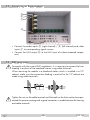
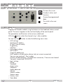
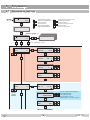
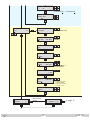
1
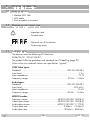
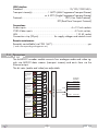
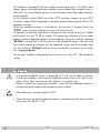
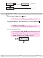
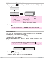
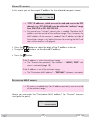
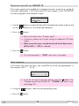
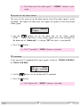
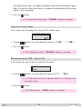
Head-End Station STC 160 4 x Digital MPEG2 Encoder to IP HDE 166 English Notes on the Assembly Instructions. As well as this supplementary Assembly Instructions, the Assembly Instructions for the STC 160 apply. GSS Grundig SAT Systems GmbH Beuthener Strasse 43 D-90471 Nuremberg Phone: Fax: E-mail: Internet: +49 (0) 911 / 703 8877 +49 (0) 911 / 703 9210 [email protected] http://www.gss.de/en Contents 1 Safety regulations........................................................................................ 3 2 General information..................................................................................... 4 2.1 Scope of delivery...........................................................................4 2.2 Meaning of the symbols used...........................................................4 2.3 Technical data................................................................................4 2.4 Description....................................................................................5 3 Installation................................................................................................... 6 3.1 Installing the Encoder module...........................................................7 3.2 Connecting the Encoder module.......................................................8 3.3 EMC regulations.............................................................................8 4 The control panel at a glance........................................................................ 9 4.1 Functions of the control panel buttons................................................9 4.2 Menu items....................................................................................9 5 Programming............................................................................................. 10 5.1 Programming procedure................................................................10 5.2 Programming the module...............................................................12 Selecting the module / channel strip...............................................13 Ethernet parameters......................................................................13 IP address of the cassette..........................................................14 Address range (subnet mask)....................................................14 Address of the gateway...........................................................15 UDP port................................................................................15 IP output signal.............................................................................16 Output IP address....................................................................17 Destination MAC address.........................................................17 Transmission protocol / Port number..........................................18 Quantity of data packets..........................................................19 Forward error correction / Transmission channel . ......................19 Transport stream ID and ORGNET ID.........................................20 Input parameter............................................................................20 Data rate of the video signal.....................................................21 TV standard............................................................................21 Aspect ratio............................................................................22 Sharpness...............................................................................22 Audio signal type and bit rate...................................................22 Level of the audio signal...........................................................23 Programme number (SID - Service ID).........................................23 Channel name........................................................................24 Factory reset................................................................................24 Saving settings ............................................................................25 6 Final procedures......................................................................................... 26 - 2 - HDE 166 1 Safety regulations • The standards EN/DIN EN 50083 resp. IEC/EN/DIN EN 60728 must be observed. • Do not perform installation and service work during thunderstorms. • Assembly, installation and servicing should be carried out by authorised electricians. • Switch off the operating voltage of the system before beginning with assembly or service work. • Avoid short circuits! • Observe the relevant standards, regulations and guidelines on the installation and operation of antenna systems. • To ensure electromagnetic compatibility, make sure all connections are tight and the covers are screwed on securely. • No liability is accepted for damage caused by faulty connections or inappropriate handling of the device. Check the head-end station according to the safety instructions listed in their assembly instruction. Take precautions to prevent static discharge when working on the device! Electronic devices should never be disposed of in the household rubbish. In accordance with directive 2002/96/EC of the European Parliament and the European Council from January 27, 2003 which addresses old electronic and electrical devices, such devices must be disposed of at a designated collection facility. At the end of its service life, please take your device to one of these public collection facilities for proper disposal. - 3 - HDE 166 2 General 2.1 S c o p e o f d e l i v e ry 1 Module HDE 166 1 LAN cable 1 Brief assembly instructions 2.2 M e a n i n g o f t h e s ym b o l s u s e d —> – – / / • 2.3 T e c h n i c a l information Important note General note Optional use of the buttons Performing works data The devices meet the following EU directives: 2006/95/EC, 2004/108/EC The product fulfils the guidelines and standards for CE labelling (page 27). Unless otherwise noted all values are specified as "typical". CVBS Video Inputs: Standard:......................................................................DIN EN 50049-1 Input level:...................................................................................... 1 Vpp Input impedance:............................................................................. 75 Ω Frequency range:........................................................... 20 Hz … 5 MHz Audio Inputs: Standard:......................................................................DIN EN 50049-1 Input level:...............................................................................500 mVrms Input impedance:........................................................................... 10 kΩ Frequency range:...........................................................20 Hz … 15 kHz MPEG2 Encoder: Transport stream:............................................. MPEG2 (ISO/IEC 13818-1) Video data stream:.......................................... MPEG2 (ISO/IEC 13818-2) Audio data stream:.......................................... MPEG1 (ISO/IEC 11172-3) Output data rate:...................................................... 2 Mbit/s…15 Mbit/s Audio data rate:....................................................... 192 kb/s…384 kb/s - 4 - HDE 166 LAN Interface Standard................................................................. 10/100/1000 MB/s Transport stream(s).......................1 MPTS (Multi Programme Transport Stream) or 4 SPTS (Single Programme Transport Stream) Protocols............................................................ UDP (User Data Protocol), RTP (Real-Time Transport Protocol) Connections: Audio inputs: .............................................................4 x 2 Cinch sockets CVBS Video inputs: . ....................................................... 4 Cinch sockets, LAN.................................................................................. 1 RJ 45 socket Connection strip (20-pin):..................... for supply voltages and control circuit Remote maintenance Remotely controllable (via PSW 160*):................................................. yes (* and a corresponding management unit) 2.4 D e s c r i p t i o n AV 1 FBAS CVBS AV 2 R L Audio-Eingang Audio input Cinch Video-Eingang Video input Cinch FBAS CVBS AV 3 R L Audio-Eingang Audio input Cinch Video-Eingang Video input Cinch FBAS CVBS AV 4 R Audio-Eingang Audio input Cinch Video-Eingang Video input Cinch R Audio-Eingang Audio input Cinch Video-Eingang Video input Cinch µP / TPS-MODUL The 4xMPEG2 encoder module converts four analogue audio and video signals into MPEG2 data streams (transport streams) and emits them via the Ethernet output. The bit rates (audio and video) are adjustable. ENCODER AV1 IP-Adresse: IP Address 227.40.50.1 AV2 227.40.50.2 AV3 227.40.50.3 AV4 227.40.50.4 AV1-AV4 227.40.50.1 SPTS IPTV OUT MPTS L L FBAS CVBS - 5 - HDE 166 The module is equipped with four video/stereo audio inputs. The fed in analogues signals are digitized and supplied to an encoder that encodes them in real time. The stereo audio signals are transferred via an adjustable amplifier to the encoder. At the Ethernet socket (RJ45) up to four SPTS transport streams or one MPTS transport stream (Multi Programme Transportstreams) according to UDP or RTP protocol is output. When the head-end station is switched on, the two-line LC display shows the "SETUP" menu and the software version of the control unit. To operate the encoder module the software version of the control unit (headend station) must be "V 10" or higher. The operating software of the encoder module and the head-end station can be updated using a PC and the software "BE-Flash" via the 9-pin D-SUB socket on the head-end station. You can find the current operating software for the head-end station and the encoder module, the software "BE-Flash" and the current assembly instructions on the website "www.gss.de/en". The encoder module is designed exclusively for use in the STC 160 head-end station. 3 Installation – Ensure the head-end station is mounted so it will not be able to vibrate. Avoid, for example, mounting the head-end station onto a lift shaft or any other wall or floor construction that vibrates in a similar way. – Before installing or changing a module, switch off the head-end station or unplug the power cable from the mains power socket. – Take measures to protect against ESD! • Open the housing of the head-end station in accordance with the assembly instructions for the STC 160. - 6 - HDE 166 3.1 I n s ta l l i n g t h e E n c o d e r m o d u l e – When installing a module, make sure that it is inserted in one of the long, numbered grooves in front of the contact strip on the board at the rear wall of the housing. – The shorter, non-numbered grooves without a contact strip on the board at the rear wall of the housing are for add-on modules only. • Open the housing of the head-end station in accordance with the assembly instructions for the STC 160. • Open the locking device A in the direction of the green arrow. A • Insert the Encoder module in grooves B of an open slot (with contact strip on the board at the rear wall of the housing) and gently slide it into the head-end station until it makes contact with the board on the rear wall. • After installing the Encoder module close the locking device A in the direction of the red arrow. —> Ensure that the ground spring C gets contact to the locking device. B C A B - 7 - HDE 166 3.2 C o n n e c t i n g t h e E n c o d e r m o d u l e D E F AV1 AV2 AV3 G • Connect the audio inputs D (right channel) / E (left channel) and video inputs F to corresponding signal sources. • Connect the LAN output G to the LAN input of a downstreamed component. 3.3 EMC AV4 r e g u l at i o n s To comply with the current EMC regulations, it is necessary to connect the lines leading in and out of the head-end station using cable terminals. When mounting the module in a head-end station which is installed in a 19" cabinet, make sure the connections leading in and out for the 19" cabinet are made using cable terminals. Tighten the nuts on the cable terminals until the teeth on the lock washer have penetrated the exterior coating and a good connection is made between the housing and cable terminals. - 8 - HDE 166 4 The control panel at a glance 4.1 F u n c t i o n s o f t h e c o n t r o l pa n e l b u t to n s M S 4.2 M e n u items Program the Encoder module using the buttons on the head-end station control panel. The menus appear on the two-line display of the control panel. The parameters and functions to be set are underlined. With the You can use the – – – – – To move the cursor To adjust values and functions To save the programmed data To switch to the next menu button select the channel strip / other modules. button to select the following menu items: LAN settings: Hardware IP address IP mask (sub net mask) IP gateway UDP-Port LAN output settings MPTS/SPTS Output IP address(es) MAC address of destination device (only at unicast connection) Transmission protocol / Port number Quantity of data packets / Forward error correction / Transmission channel Transport stream and ORGNET-ID Input settings Bitrate Standard Aspect ratio Sharpness Audio data rate Volume Station number Station name Factory reset Save data - 9 - HDE 166 5 Programming 5.1 Progr a mming Ein/On SETUP procedure BE160 V 10 Bx 1 ……… ……… ……… Bedienhinweise "blättert" Menüs vorwärts. M wählen die Eingabeposition / wählt Untermenü stellen Werte ein,. / S speichert alle Eingaben. 1 zeigt die Eingabeposition Operating Hints scrolls forward through the menu. M select the enter position. / selects a submenu. set values and triggers actions. / S saves all entries. 1 shows the enter position A page 11 Bx 2 IP 4xENCODER V2 / Bx 3 ……… ……… ……… > 2 sec. = abbrechen / cancel Bx 2 static ETHERNET => Bx 2 IP-ADDR 192.168. 0.128 DHCP Bx 2 IP-MASK 255.255. Bx 2 255. 0 IP-GATEWAY 192.168. 0. Bx 2 1 UDP-PORT 60000 Bx 2 MPTS SPTS SPTS SPTS SPTS 1 2 3 4 IP-OUT => IP 1…4 OUT-IP 227. 40. 50. 60 IP 1…4 0022B7000000 IP 1…4 1234 IP 1…4 7 1…4 /RTP PKTS/FEC off 1…7 / 10/09 AnnexB / … / 20/19 AnnexB - 10 - IP only if IP address is out of multicast range –> Unicast connection MODE/PORT UDP nur wenn IP-Adresse außerhalb des Multicastbereichs liegt –> Unicastverbindung DEST-MAC TS/ONID HDE 166 1234 UDP IP 1…4 7 IP /RTP PKTS/FEC off 1…7 / 10/09 AnnexB / … / 20/19 AnnexB 1…4 TS/ONID 0x0001,0100 Bx 2 INPUT AV 1 => BITRATE AV 1…4 /2…15/off/Audio only 5.0 Mbps AV 1…4 AV 1…4 NORM PAL BG 4.43 MHz AV 1…4 ASPECT /PAL N 3.58 MHz /16:9 4:3 AV 1…4 SHARPNESS normal /sharp/soft AV 1…4 Stereo AUDIO 256 kbps AV 1…4 /Joint/Dual/Mono L 192/256/320/384 VOLUME -11…+11 0 dB AV 1…4 PRG-NUM 1…255 ! 00001 AV 1…4 ! = Programmnummer ist bereits belegt ! = Programme number is already in use NAME PROG 1 Bx 2 FACTORY Defaults => Werkeinstellung aufrufen invoke factory defaults M Bx 2 MEMORY M FACTORY STORE => S S A page 10 M S => STORE Bx 2 Einstellung speichern S store factory defaults - 11 - STORE A HDE 166 M Bx 2 M MEMORY S => STORE Einstellung speichern S store factory defaults STORE A page 10 M A page 10 CANCEL 5.2 P r o g r a m m i n g the module Notes: – Entries are saved by pressing the button. —> You will be returned to "Selecting the module/channel strip". – The programming process can be cancelled by pressing and holding the button. —> Changes will NOT be saved. —> You will be returned to "Selecting the module/channel strip". • Switch on the head-end station. —> The display shows "SETUP BE160" and the software version of the head-end station (e.g. V 10). —> The output level of the output collector can be adjusted in the "SETUP" menu (see STC 160 assembly instructions). Ein / On SETUP BE160 V 10 - 12 - HDE 166 Selecting • If necessary, press to be programmed. the module ……… Bx 2 / channel strip repeatedly to select the particular module (Bx …) ……… 4xENCODER IP V2 / Bx 3 ……… ……… ……… —> The display shows e.g. the menu Bx 2 4xENCODER IP V 2. "Bx 2" stands for slot 2 "4xENCODER IP" type of module "V 2" software version of the module • Press the button. —> The "Ethernet settings" – "ETHERNET" main menu is activated. Ethernet In this menu you specify whether the Ethernet parameters for the prospectively intended control of the cassette are entered … – automatically by a connected server ("DHCP") or – manually via the menu ("static"). To assign the cassette uniquely, each IPTV cassette must be allocated its own IP address. pa r a m e t e rs —> If no Ethernet settings should be done, press button . The "IP output signal" – "OUTPUT" main menu is activated (page 16). Bx 2 off ETHERNET => Bx 2 static ETHERNET => Bx 2 DHCP ETHERNET => • Press the buttons to select … – manual setting ("static") or – automatic setting ("DHCP") of the Ethernet parameter. - 13 - HDE 166 • Press the button to activate the setting options. —> The "IP address of the cassette" – "IP-ADDR" submenu is activated. IP a d d r es s If you choose to enter the Ethernet parameters manually, set the IP address of the cassette in this menu. If "DHCP" is selected, the "IP-ADDR", "IP-MASK" and "IP-GATEWAY" sub-menus display the parameters that were assigned automatically by a connected server. If a server is not connected, " 0. 0. 0. 0*" appears in the corresponding menu. The star " * " in the display means that the data is provided by a DHCP server. of the cassette Bx 2 IP-ADDR 192.168. • Use the and use • Press the 0.128 buttons to select the digits of the IP address displayed to be set to set the desired IP address. button. —> The "Address range (subnet mask)" – "IP-MASK" submenu is activated. Address In this menu you define the address range for the cassettes connected to the LAN network. range (s u b n e t mask) Bx 2 IP-MASK 255.255. • Use the and use • Press the 255. 0 buttons to select the digit of the subnet mask displayed to be set to set the desired subnet mask. button. —> The "Address of the gateway" – "IP-GATEWAY" submenu is activated - 14 - HDE 166 Address The address of a gateway (server) can be set in this menu. If no gateway is used you can skip this setting. o f t h e gat e way Bx 2 IP-GATEWAY 192.168. • Use the and use • Press the 0. 1 buttons to select the digit of the IP address displayed to be set to set the desired IP address. button. —> The "UDP port" – "UDP-PORT" submenu is activated. UDP p o r t The UDP port setting is required if the cassette needs to be reached externally for remote maintenance. Bx 2 UDP-PORT 60000 • Use the and use • Press the buttons to select the digit of the port number displayed to be set to set the desired port number ("0" … "65535"). button. —> Return to the main menu "Ethernet parameters" • Press the button. —> The "IP Output" – "OUTPUT IP" main menu is activated. - 15 - HDE 166 IP o u t p u t Herein you select whether you would like to generate – a MPTS data stream, which includes all input signals, or – four SPTS data streams, each one input signal included. In addition you get access to the submenus for IP output and TS/ONID(s) settings . signal —> If no IP output settings should be done, press button . The "Input parameter" – "INPUT" main menu is activated (page 20). Bx 2 MPTS • Using the SPTS 1…4). IP-OUT => buttons select the desired kind of data stream (MPTS or —> If "MPTS" is selected the IP output settings must only be passed one time because all input signals are included in one data stream. If "SPTS" is selected the IP output settings must be passed four times (SPTS 1 … SPTS 4), because for each input signal a separate data stream will be generated. • Press button . —> The "Output IP address" – "OUT-IP" submenu is activated. - 16 - HDE 166 O u t p u t IP a d d r es s In this menu you set the output IP address for the selected transport stream. IP 1…4 OUT-IP 227. 40. 50. 60 —> "IPTV" IP addresses, which are used to send and receive the IPTV channels (e.g. 227.40.50.60) must be within the "multicast" range from 224.5.0.0 to 231.255.255.255. —> For special uses "Unicast" transmission is needed. Therefore the IP address must be outside of the multicast range. Then, however, the MAC address of the receiver is needed. If an IP address outside of the multicast range is set, below the menu for entering the MAC address of the receiver is displayed. • Press the • Using the • Press the buttons to select the digit of the IP address to be set. buttons set the desired IP address. button. If the IP address is within the multicast range: —> The "Transmission protocol / Port number" – "MODE / PORT" submenu is activated (page 18). If the IP address is out of the multicast range: —> The "Destination MAC address" – "DEST-MAC" submenu is activated. D e s t i n at i o n MAC a d d r es s —> This menu is enabled only if an IP address previously was set outside of the multicast range. Herein you can enter the "Destination MAC address" for "Unicast" transmission (point to point). IP 1…4 DEST-MAC 0022B7000000 - 17 - HDE 166 • Using the • Using the • Press the buttons select the digit of the MAC address displayed to be set. buttons set the desired MAC address. button. —> The "Transmission protocol / Port number" – "MODE / PORT" submenu is activated. Tr a n s m i s s i o n In this menu you can define the transmission protocol and the port number. p r oto c o l / P o r t IP 1…4 number MODE/PORT UDP 1234 Selecting the transmission protocol • Press the button to select "UDP". • Using the buttons to select the desired transmission protocol: —> "UDP" – The "User Datagram Protocol" is for the connectionless (without handshake) transmission of data to a certain application. The port number of the service is also sent which the data should obtain. —> "RTP" – The "Real-time Transport Protocol" is for continuously transmitting multimedia data streams in an IP network. Unlike UDP, the header is transmitted which makes the data transmission more robust. Setting the port number • Using the buttons select the digit of the port number displayed to be set. • Using the buttons set the desired port number. • Press the button. —> The "Quantity of data packets, Forward error correction, Transmission channel" – "PKTS / FEC" submenu is activated. - 18 - HDE 166 Q ua n t i t y o f data pac k e t s F o rwa r d error correction In this menu you set the quantity of the data packets to be transmitted, the forward error correction FEC and the transmission channel. If the forward error correction is used the data to be transmitted is encoded in a redundant way so that the addressee can correct transmission errors. / T r a n s m i s s i o n IP 1…4 7 channel PKTS/FEC off Defining the quantity of data packets • Press the button to select the data packet digit. • Using the buttons define the quantity of MPEG data packets in one IP data packet ("1" … "7"). Setting the forward error correction • Press the button to select the forward error correction. —> In position "off" the forward error correction (FEC) is switched off. • Using the "20/19"). buttons set the desired value of the FEC ("off", "10/9" … Setting the transmission channel • Press the button to select"Annex…". • Use the buttons to set the desired transmission channel ("AnnexA" / "AnnexB"). • Press the button. —> The "Transport stream ID and ORGNET ID" – "TS/ONID" submenu is activated. - 19 - HDE 166 Tr a n s p o r t s t r e a m ID a n d ORGNET ID If the input signals are encoded to a separate transport stream (e.g. setting of the output signal path -> ASI without any ASI input signal), a new ORGNET-ID must be assigned to the transport stream. IP 1…4 TS/ONID 0x0001,0100 • Use the use the buttons to select the digit of the hexadecimal number to be set and buttons to set the desired character. • Press the button. —> Return to the main menu "IP output signal" —> If necessary perform the IP output settings for additional SPTS data streams. —> When you exit the menu, note that the desired kind of data stream – MPTS or SPTS 1… SPTS 4 – is be set! • Press the button. —> The "Input parameter" – "INPUT" main menu is activated. Input In this menu you select the input, you would like to set the input parameters in the submenus (AV 1 … AV 4). pa r a m e t e r Bx 2 INPUT AV 1 => —> If you do not want to do input settings, press the button. The "Transport stream ID and ORGNET ID" – "TS/ONID" main menu is activated (page 20). • Using the • Press the buttons select the corresponding input. button. - 20 - HDE 166 —> The "Data rate of the video signal " – "BITRATE" submenu is activated. D ata You can use this menu to set the data rate at which the video signal is to be encoded. The higher the data rate, the higher the quality of the transmitted video signal. r at e o f t h e v i d e o s i g n a l AV 1…4 BITRATE 10.0 Mbps • Use the buttons to set the data rate of the video signal ("2.0" … "15.0" Mbit/sec). If only audio signals are to be encoded, set the data rate to "Audio only". In setting "Off" the input is switched off. • Press the button. —> The "TV standard" – "NORM" submenu is activated. TV s ta n da r d In this menu the TV standard of the input signal is to be set - "PAL BG 4.43 MHz" or "PAL N 3.58 MHz". • Use the • Press the AV 1…4 NORM PAL BG 4.43 MHz buttons to set the desired TV standard. button. —> The "Aspect ratio" – "ASPECT" submenu is activated. - 21 - HDE 166 Aspect In this menu the aspect ratio of the encoded signal is to be set - "16:9" or "4:3". r at i o AV 1…4 ASPECT 4:3 • Use the • Press the buttons to set the desired aspect ratio. button. —> The "Sharpness" – "SHARPNESS" submenu is activated. Sharpness In this menu the you set the desired sharpness - "normal", "sharp" or "soft". AV 1…4 SHARPNESS normal • Use the • Press the buttons to set the desired sharpness. button. —> The "Audio signal type and bit rate" – "Audio" submenu is activated. Audio In this menu you set the signal type and the bit rate the audio signal is to be encoded. s i g n a l t y p e a n d b i t r at e AV 1…4 Stereo AUDIO 256 kbps • Use the buttons to set the signal type – "Stereo", "Joint Stereo" (subjectively improved stereo impression), "Dual Channel" (dual channel sound) or "Mono L" (left) - of the audio signal. • Use the button to select the bit rate setting and set it as desired with the buttons ("192" … "384" kbit/sec). - 22 - HDE 166 The higher the bit rate, the higher the quality of the transmitted audio signal. Bear in mind that when the bit rate is increased, the bandwidth of the output signal is also increased. • Press the button. —> The "Level of the audio signal" –"VOLUME" submenu is activated. Level In this menu you can adapt the volume of this audio input. o f t h e au d i o s i g n a l AV 1…4 VOLUME 0 dB • Use the • Press the buttons to set the desired volume ("– 11dB" … "+ 11dB"). button. —> The "Programme number" –"PRG-NUM" submenu is activated. Progr a mme In this menu you can set the Service ID of the input. number (SID - S e rv i c e ID) AV 1…4 PRG-NUM 00001 • Use the buttons to set the desired Service ID ("1" … "255"). —> A "!" behind the Service ID indicates that this ID is already in use by another input. • Press the button. —> The "Channel name" – "NAME" submenu is activated. - 23 - HDE 166 Channel In this menu the channel name of the input can be set. name AV 1…4 NAME PROG 1 • Use the buttons to select the digit of the channel name to be set and use buttons to set the desired character (" ", "0…9", "A…Z", "Ä", "Ö", "Ü", "a…z", "ä", "ö", "ü", "+", "-", "/", ":" or "*"). • Press the button. —> Return to the main menu "Input parameter" • Use the buttons to select the 2nd AV input and carry out its settings analogous to that of the 1st AV input, or • Press the button. —> The "Factory reset" – "FACTORY Defaults" main menu is activated. Fac to ry In this menu you can reset all settings to the factory defaults. reset Bx 2 FACTORY Defaults Bx 2 => M • Press the FACTORY STORE => S S M button. —> The factory defaults are invoked ("FACTORY STORE"). —> By pressing the button, you will be returned to the main menu "Selecting the module" (page 13). • Press the button. - 24 - HDE 166 —> The factory defaults are saved. The display shows "STORE" —> Back to "Selecting the module" (page 13). S av i n g s e t t i n gs Bx 2 MEMORY S => STORE S STORE M CANCEL • All programmed data is saved by pressing the button. —> The settings are saved. —> Return to "Selecting the module / channel strip" (page 13). —> By pressing the button, you will be returned to the menu item "Selecting the module / channel strip" without saving the programmed data. - 25 - HDE 166 6 Final procedures After installing the head-end station, upgrading accessories or installing modules it is necessary to tighten all cable connections, cable terminals and cover screws in order to maintain compliance with current EMC regulations securely. • Mount the base plate and the front cover (see STC 160 assembly instructions). - 26 - HDE 166 Declaration of CE conformity Service: Phone: +49 (0) 911 / 703 2221 • Fax: +49 (0) 911 / 703 2326 • Email: [email protected] Grundig SAT Systems GmbH • Beuthener Straße 43 • D-90471 Nürnberg Alterations reserved. Technical data E. & O.E. © by GSS GmbH V1/13122012