1
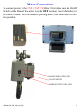
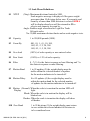
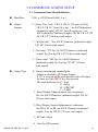
MANUAL P/N: 5999-1041-00 (4/15) 1 TABLE OF CONTENTS Meter Connections----------------------------------------------------------3 Operation---------------------------------------------------------------------4-5 1.0 Scale Procedure---------------------------------------------------------6 1.1 Software Navigation Flowchart-----------------------------------6-7 1.2 Navigation Keys-----------------------------------------------------7 1.3 Scale Menu Definitions---------------------------------------------8-9 1.4 Numeric Entries------------------------------------------------------10 1.5 Set Up Entries--------------------------------------------------------10 2.0 Calibration Procedures--------------------------------------------------11 2.1 Calibration Menu Definitions--------------------------------------11 2.2 Calibration------------------------------------------------------------12 2.3 Linearity Correction-------------------------------------------------12 3.0 Communications Setup-------------------------------------------------13 3.1 Communications Menu Definitions--------------------------------13-14 4.0 Testing Procedure--------------------------------------------------------15 4.1 Testing Menu Definitions--------------------------------------------15 5.0 Warnings-------------------------------------------------------------------16 6.0 Warranty-------------------------------------------------------------------17 7.0 Assistance-----------------------------------------------------------------17 MANUAL P/N: 5999-1041-00 (4/15) 2 Meter Connections To connect power to the CSW-15AT-CS Meter. First make sure the On/Off Switch on the Rear of the meter is in the OFF position. Insert the battery in the battery holder, with the contacts pointing down, then slide down to lock into position. CHARGE INDICATING LED ON/OFF SWITCH CHARGE INDITCATING LED MANUAL P/N: 5999-1041-00 (4/15) 3 OPERATION Key Functions: ZERO Brings the scale to a zero balance reading. If the Zero key is pressed and held for 5 seconds the Calibration zero value will be displayed. GRS/NET Toggles the display between Gross weight and Net weight. This key is also used to enter setup mode. Begin by pressing and hold this key until the Parameter and Calibration Event counters are displayed. Immediately after (within 5 sec.) enter in sequence Tare, lb/kg, GRS/NET, and Print/Enter, the display will indicate ScAlE. -P xxx and C xxx are event counters that will increment once each time one or more changes are made to the scale or Calibration Parameters. TARE Enters the Gross weight value into the Tare display and switches to the Net display mode. If the Tare key is pressed and held for 5 seconds the current Tare value will be displayed. lb/kg Toggles the display between pounds and kilograms. PRINT Outputs the displayed weight data to the RS-232 Port. Note: All keys are disabled when the scale is in motion or overload. Error Messages: SCnEg When the weight is more than 10 divisions negative from the zero calibration point. oLD The Scale is in an overload condition. bAt LO Will flash when the battery voltage falls to 6.9VDC and will be displayed continuously when the voltage falls to 6.5VDC. Err d More than 5000 scale divisions have been selected in S1 Ntep and S1 angle mode. More than 20,000 scale divisions have been selected in S1 NO mode. MANUAL P/N: 5999-1041-00 (4/15) 4 OPERATION CONTINUED Charging the Battery: When the battery voltage falls to 6.5VDC, as described previously, bAt LO will be displayed continuously. The battery needs to be charged at this time. With the on/off switch in the OFF position, connect one end of the power adapter to a 110VAC outlet. Next connect the other end of the adapter to the power jack on the rear of the meter. The charge indicating led will be orange while the battery is being charged and turned off when the battery is fully charged. Turn the on/off switch to the ON position and the meter will be fully operational as the battery is being charged. CHARGE INDICATING LED MANUAL P/N: 5999-1041-00 (4/15) 5 1.0 SCALE PROCEDURE 1.1 SOFTWARE NAVIGATION FLOWCHART SCALE CALIBRATION S1 Ntep Ntep,no,angle (Ntep) S2 CAPACITY 1-999,999 (5000) S3 COUNT BY S4 OVERLOAD C1 RS-232 SHOW RAW COUNTS THEN 0 R1 BAUD RATE 1200,8,N,1- C2 ZERO SHOW RAW COUNTS THEN 0 R2 1,2,5,/DEC (1) C3 SPAN POINT SHOW ACTUAL WEIGHT 105% OF CAP C4 SPAN POINT OR ENTERED Zero & Clear All Points 19200,8,N,1? T1 VERSION SOFTWARE VERSION Output Format WT ONLY, G, N (GTN) T2 DISPLAY LIGHT SEGMENTS R3 Output Type (Key) Polled, Continuous T3 BUTTONS b1-b4, b5 EXITS R4 (Disabled) Rec.,Remote T4 A TO D A/D RAW COUNTS T5 SERIAL Jumper Rx,Tx Receiver mode S5 ZERO LIMIT 100%,1.9% (100%) C5 SPAN POINT S6 FILTER 0 fastest to 7 slowest (3) C6 SPAN POINT T6 Cal Factors ? S7 1 TO 99 Divisions (2) C7 SPAN POINT T7 DEFAULT 0 to 99 UPDATES (4) END END MOTION BAND S8 MOTION DELAY MANUAL P/N: 5999-1041-00 (8/11) END TEST END Loop Back YES, NO 6 1.1 SOFTWARE NAVIGATION FLOWCHART (CONTINUED) S9 Normal, Blank, Motion Display Dashes (Normal) S10 ZERO BAND 1-99 DIVISIONS(2) S11 ZERO DELAY 0-99 UPDATES(2) S12 1-99 Zero Tracking DIVISIONS(1) S13 Tracking DELAY 1-99 1/4secinc.(0) S14 Display lb/kg lb ,kg, lb/kg (lb/kg) S15 SCALE ID 1-99 (1) S16 BRIGHTNESS S17 SLEEP MODE ID IN TX 1-15 (15) 0 to 30 min blanks dsp (0) END MANUAL P/N: 5999-1041-00 (8/11) 1.2 NAVIGATION KEYS During setup you will be required to make numeric entries. (Ex: Capacity, Zero Band, etc...) The following table outlines the keys used to perform these entries along with their function. ZERO-------KEY IS USED TO NAVIGATE UP. GRS/NET---KEY IS USED TO NAVIGATE DOWN. TARE--------KEY IS USED TO NAVIGATE LEFT. lb/kg---------KEY IS USED TO NAVIGATE RIGHT. PRINT-------KEY IS USED TO ENTER DATA AND RETURNS. 7 1.3 Scale Menu Definitions: S1 NTEP (Ntep): Maximum divisions limited to 5000. Scale negative message is displayed if the gross weight goes more than 10 divisions below zero. If a capacity and count by of more than 5000 divisions is selected ERR d will be displayed and you will be returned to S2 to select a new capacity or count by. Angle: Enables angle correction for Legal For Trade lift truck scales. No: 20,000 maximum division limits and no scale negative tests. S2 Capacity 1 to 950,000 pounds (5000). S3 Count By .001, 01, .1, (1), 10, 100, .002, 02, .2, 2, 20, 200 .005, 05, .5, 5, 50, 500 S4 Over load (105%) of scale capacity or user entered value. S5 Zero Limit (100%) or 1.9% of scale capacity. S6 Filter 0 - 7 (3) 0 is the fastest response or least filtering and 7 is the slowest response or most filtering. S7 Motion Band 1 to 99 updates (2) the weight display must be stable within the selected number of updates for the motion indicator to be turned off. S8 Motion Delay 0 to 99 updates (4) the weight display must be within the motion band for the selected number of updates for the motion indicator to be turned off. S9 Motion (Normal): When the scale is in motion the motion LED will Display light. Blank: When the scale is in motion the display will be blanked out. Dashes: When the scale is in motion the display will show all dashes. S10 Zero Band MANUAL P/N: 5999-1041-00 (8/11) 1 to 99 divisions (2) the weight display must return to zero within the selected number of divisions to to be considered zero. 8 1.3 Scale Menu Definitions Continued: S11 Zero Delay 0 to 99 updates (4) the weight display must be within the zero band for the selected number of updates to be considered Zero. S12 Zero Tracking 1 to 99 divisions (2) the number of graduations allowed to be Automatically Zeroed off. S13 Tracking Delay 0 to 99 [15second increments] (10) the amount of time the display must be within the allowed graduations before it will be automatically Zeroed. S14 Lb/Kg (Lb/KG): Allows the indicator to be switched between pounds and kilograms by pressing the lb/kg key. LB: This sets the display to Pounds only. Kg: This sets the display to Kilograms only. S15 Scale ID (1) to 99 scale ID used in RF link output. S16 Brightness 0 to (15) adjusts the LED display intensity 15 is the brightest. S17 Sleep Mode (0) to 30 minutes. The display will turn off after the the set amount of time elapses with no scale activity. END Exits back to the main Menu. ( ) indicates Factory Set defaults. MANUAL P/N: 5999-1041-00 (8/11) 9 1.4 Numeric Entries: When entering a numeric value, first press and release the lb/kg key to move right into the menu where the numeric value will be entered. Then press and release the ZERO key, the first digit in the value will flash. Press and release the ZERO and GRS/NET keys to increase or decrease the digits value. Press and release the Tare key to move to the next digit. Repeat the steps above to adjust the digits value. Repeat all steps until the numeric value is correct, then press and release the PRINT key to enter the data. The display will return to the menu. 1.5 Set Up Parameters: To begin press and hold the GRS/NET key until the Parameter and Calibration Event counters are displayed. Immediately after (within 5 seconds) enter in sequence Tare, lb/kg, GRS/NET, and Print/Enter, The display will indicate ScAlE -P xxx and C xxx are event counters that will increment each time one or more changes are made to the Scale or Calibration Parameters. With the display indicating ScAlE, press the GRS/NET key to move down. This allows the operator to change any of the scale Parameters S1 thru S17 For example, press the GRS/NET key to move down until S2 is displayed, S2 is used to set the Capacity of the Scale. Press the lb/kg key to move right in the S2 Parameter. The current capacity will be displayed. Press the ZERO key, the first digit will flash. Enter the capacity using the steps described in section 1.3. When the capacity is correct, press the PRINT key to enter the value. The display will return to S2. To enter the Count By, press the GRS/NET to move down, S3 will be displayed. Press the lb/kg key to move right into this parameter. The current "Count by" will be displayed. Press the ZERO and GRS/NET keys to adjust the divisions. Press the Tare and lb/kg keys to adjust the decimal point. Press the PRINT key, when finished, to enter the data. The display will return to S3. Exit Set up Mode by pressing the Tare key, End will be displayed, then press Print/Enter. MANUAL P/N: 5999-1041-00 (8/11) 10 2.0 CALIBRATION PROCEDURES 2.1 Calibration Menu Definitions: C1 Zero All Raw counts, (pitch and roll if in angle mode) will be displayed. When ZERO is pressed an analog zero is done and all calibration span points will be cleared. If in angle mode the pitch and roll offsets will also be zeroed. C2 Zero Zeroed Raw counts, (pitch and roll if in angle mode) will be displayed. When ZERO is pressed an analog zero is done and all calibration span points will NOT be cleared. If in angle mode the pitch and roll offsets will also be zeroed. C3 Span Point The last calibration weight will be displayed then the actual weight on the scale will be displayed. If you do not wish to change the span point, press the TARE key to exit without making any changes. If the displayed weight does not match the known test weight, press the ZERO key to enter the correct weight. Use the steps described in section 1.4 for numeric entry. When the weight is correct press the PRINT key to enter the new value. C4 to C7 Span points C4 to C7 are for linearity correction. They can be used in order and in any quantity or not at all if no correction is necessary. You may also return to C4 to C7 later and add a new correction point without affecting any original calibration points. The last calibration weight will be displayed then the actual weight on the scale will be displayed. If no calibration weight has been entered at this span point "notset" will be displayed then the actual weight on the scale is displayed. If the displayed weight does not match the known test weight, follow the steps described for C3 Span point on adjusting the weight and entering the value. END Exits back to the main Menu. MANUAL P/N: 5999-1041-00 (8/11) 11 2.2 Calibration Press and hold the GRS/NET key, as described previously in section 1.4. ScAlE will be displayed. Press the lb/kg key to move right, CALib will be displayed. Press the GRS/NET key to move down, C1 will be displayed. Press the lb/kg key to move right, raw counts will be displayed. With no weight on the scale, press the ZERO key, “0” will be displayed. Press the PRINT key to enter the data. "0" is now entered and the display returns to C1. Note: Use C1 or C2 to zero. There is no need to use both C1 and C2. Next, press GRS/NET key to move down, C3 will be displayed. Press the lb/kg key to move to the right, the last calibrated weight will flash then the current weight on the scale is displayed. Place a known test weight on the scale. Press the ZERO key, the first digit of the weight will flash. Use the ZERO and GRS/NET keys to increase or decrease the digits value. Press the TARE key, to move left, the next digit will flash. Repeat these steps until the correct weight is entered. Press the PRINT key to enter the data. The display will return to C3. Press the GRS/NET key until End is displayed, then Press PRINT to return to the operation mode. Calibration is now complete. 2.3 Linearity Correction If Linearity Correction is needed, Press the GRS/NET key (from the calibration menu) to move down to C4. Press the lb/kg key to move right, the last calibrated weight will flash or “notset” will flash if this point has not been previously set. Next, the current weight on the scale will be displayed. Place a known test weight on the scale. Press the ZERO key for the first digit of the displayed weight to flash. Enter the weight as described in section 1.4, then press the PRINT key to record the data. Continue these steps for C5, C6 and C7. Linearity Correction points (C4-C7) can be used in any order and in any quantity or not at all if no correction is necessary. After calibration is complete you may also return to these correction points and make changes to its value without affecting any of the original calibration points. MANUAL P/N: 5999-1041-00 (8/11) 12 3.0 COMMUNICATIONS SETUP 3.1 Communications Menu Definitions: R1 Baud Rate 1200 to 115200 baud (9600), 8, n, 1 R2 Output Format 0 - (Gross, Tare, Net)- "CR, LF, CR, LF [32 bytes of 2Eh], CR, LF, CR, LF, Gross (lb or kg), :, six ASCII characters [indicated weight], CR, LF, Tare (lb or kg), sp, :, six ASCII characters (indicated weight), CR, LF, CR, LF, CR LF, CR, LF" [100 bytes total output. 1 - (Weight only)- "Six ASCII Characters [indicated weight], CR, LF" [8 bytes total output]. 2 - (Net only)- "NT, Sp, Six ASCII Characters [indicated weight], Sp, lb or kg, CR, LF" [14 bytes total output]. 3 - (Gross only)- "GR, Sp, Six ASCII Characters [indicated weight], Sp, lb or kg, CR, LF" [14 bytes total output]. R3 Output Type 0 - Output on command, standard print. Output as selected by R2 Output Format. If "Q" is received on the serial port the scale will output the same as if the PRINT key were pressed. The same holds true for Z = Zero U = lb/kg D = GRS/NET T = TARE 1 - Slave Display Output (numeric only) continuous Stx, Six ASCII Characters (indicated weight), CR, LF [9 bytes total output]. 2 - Slave Display Output (alphanumeric) continuous Stx GR or NT or TR, six ASCII Characters (indicated weight), lb or kg, CR, LF [15 bytes total output] 3 - RF Link Output 4 - Used for QSI terminal MANUAL P/N: 5999-1041-00 (8/11) 13 3.0 COMMUNICATIONS SETUP 3.1 Communications Menu Definitions Continued: R4 Receiver 0 - Disabled - normal scale mode. 1 - Standard Receiver Receives R3.3 RF link output string displaying data as it appears on the scale. All keys are disabled except the PRINT key. 2 - Remote control. Receives R3.3 RF link output string displaying data as it appears on the scale and allows full control of all scale meter functions. END Exits back to the main Menu. ( ) indicates Factory Default setting MANUAL P/N: 5999-1041-00 (8/11) 14 4.0 TESTING PROCEDURES 4.1 Testing Menu Definitions: T1 Version Displays Software Version. T2 Display Lights all display segments and indicating LEDs. T3 Buttons Press the ZERO key, b1 will be displayed. Press the GRS/NET key, b2 will be displayed. Press the Tare key, b3 will be displayed. Press the lb/kg key, b4 will be displayed. Pressing the PRINT key will exit back to the menu T3. T4 A to D Displays Raw counts where a 1mV/V signal from the scale will display 25,000 counts. When in angle mode Down GRS/NET will cycle Pitch, Roll and Raw counts. T5 Serial Serial communications can be verified by connecting pins 2 and 3 on the serial port. A single character will be echoed and pass or fail will be displayed. T6 Setup data Setup data will be sent out on the printer port. T7 Default Resets the meter back to factory defaults clearing all calibration and setup data. "r you sure?" will be displayed then press the Tare key to exit without defaulting, or press the PRINT key to reset the meter to factory default. END Exits back to the main Menu. MANUAL P/N: 5999-1041-00 (8/11) 15 WARNINGS AND APPLICATION INSTRUCTIONS 5.0 WARNINGS WARNING Loads may diagnose from hook if proper procedures are not followed. A falling load may cause serious injury or death. Hook must always support the load. The load must never be supported by the latch. Never apply more force than the hook’s assigned Working Load Limit (WLL) rating. Read and understand these instructions before using the hook. If your hook or lifting eye becomes loose, remove the scale from operation and contact CAMBRIDGE SCALE WORKS, INC. immediately @ 1-301-724-4082 Particle or Dye Penetrant. (Note: Some disassembly may be required.) Never use a hook whose throat opening has been increased, or whose tip has been bent more than 10 degrees out of plane from the hook body, or is in any other way distorted or bent. Note: A latch will not work properly on a hook with a bent or worn tip. Never use a hook that is worn beyond the limits shown in Figure 1. Remove from service any hook with a crack, nick or gouge. Hooks with a crack, nick, or gouge shall be repaired by grinding lengthwise, following the contour of the hook, provided that the reduced dimension is within the limits shown in Figure 1. Never repair, alter, rework, or reshape a hook by welding, heating, burning or bending. Never side load, back load, or tip load a hook. (Side loading, back loading and tip loading are conditions that damage and reduce the capacity of the hook). (See Figure 2.) Eye hooks, shank hooks and swivel hooks are designed to be used with wire rope or chain. Efficiency of assembly may be reduced when used with synthetic material. Do not swivel the S-322 swivel hook while it is supporting a load. The S-322 is distinguishable by hex nut and flat washers. The S-322 swivel hook is designed to rotate under the load. The S322 is distinguishable from the S-322 by use of a round designed to shield bearing. The frequency of bearing lubrication on the S-322 depends upon the frequency and period of product use as well as environmental conditions, which are contingent upon the user’s good judgment. The use of a latch may be mandatory by regulations or safety codes; e.g., OSHA, MHSA, ANSI/ASME B30, Insurance, etc., (Note: When using latches see instructions in “Understanding: The Crosby Group Warnings” for further information.) Always make sure the hook supports the load. (See Figure 3). The latch must never support the load (See Figure 4). When placing two (2) sling legs in hook, make sure the angel from the vertical to the outermost leg is not greater than 45 degrees, and the included angle between the legs does not exceed 90 degrees* (See Figure 5). See ANSI/ASME B30.10 “Hooks” for additional information. Hoist hooks incorporate markings forged into the product which address two (2) QUIC-CHECK features: Deformation Indicators- Two strategically placed marks, one just below the shank or eye and the other on the hook tip, which allows for a QUIC-CHECK measurement to determine if the throat opening has changed, thus indicating abuse or overload. To check, use a measuring device (i.e., tape measure) to measure the distance between the marks. The marks should align to either an inch or half-inch increment on the measuring device. If the measurement does not meet criteria, the hook should be inspected further for possible damage. Angle Indicators-Indicates the maximum included angle which is allowed between two(2) sling legs in the hook. These indicators also provide the opportunity to approximate other included angles between two sling legs. IMPORTANT SAFTEY INFORMATIONREAD AND FOLLOW A visual periodic inspection for cracks, nicks, wear, gouges, and deformation as part of a comprehensive documented inspection program, should be conducted by trained personnel in compliance with the schedule in ANSI B30.10. For hooks used in frequent load cycles or pulsating loads, the hook and threads Should be periodically inspected by Magnetic. MANUAL P/N: 5999-1041-00 (8/11) * For two legged slings with angles greater than 90 degrees, use an intermediate link such as a master link or bolt type shackle to collect the legs of the slings. The intermediate link can be placed over the hook to provide an in-line load on the hook. This approach must also be used when using slings with three or more legs. 16 6.0 WARRANTY CAMBRIDGE warrants the CSW-15AT-CS to be free of defects in workmanship and/or materials for 12 months from the date of shipment. This warranty of workmanship and/or materials, is valid, if in the opinion of CAMBRIDGE, the equipment has not been mechanically, environmentally, or electrically abused. This warranty is limited, at the option of CAMBRIDGE, to repair, replace or an appropriate credit adjustment not to exceed the original equipment sale price paid to CAMBRIDGE. CAMBRIDGE assumes no liability in connection with the sales of its products beyond that stated above. Warranty replacement parts and/or repair services are performed at the factory in Cumberland, Maryland or by an authorized Service Group approved by CAMBRIDGE. Warranty does not include travel expense if a factory technician is requested to perform repairs at a location other than the factory. It the user's responsibility to follow the proper set-up, calibration and operating procedures of the CSW15AT-CS as described in this manual. If the operator has difficulty using their CSW-15AT-CS indicator properly, please contact CAMBRIDGE at 1-301-724-4082. Any one of our Technicians will be happy to work with the user via telephone. Thank You! 7.0 ASSISTANCE: If at any time you require assistance with your CSW-15AT-CS Crane Scale: End User please contact your servicing scale dealer. Authorized Cambridge Dealer/ Distributor please contact: CAMBRIDGE SCALE WORKS, INC. 115 West Mary Street Cumberland, MD 21502 Phone: (301) 724-4082 Fax: (301) 724-4964 MANUAL P/N: 5999-1041-00 (8/11) 17